
Abstract
The purpose of this study was to design a new automated stiffness measurement device which could perform a simultaneous measurement of both dorsi- and plantarflexion angles and the corresponding resistive torque around the rotational centre of an articulated ankle-foot orthosis (AAFO). This was achieved by controlling angular velocities and range of motion in the sagittal plane. The device consisted of a hydraulic servo fatigue testing machine, a torque meter, a potentiometer, a rotary plate and an upright supporter to enable an AAFO to be attached to the device via a surrogate shank. The accuracy of the device in reproducing the range of motion and angular velocity was within 4% and 1% respectively in the range of motion of 30&dG (15&dG plantarflexion to 15&dG dorsiflexion) at the angular velocity of 10&dG /s, while that in the measurement of AAFO torque was within 8% at the 0&dG position. The device should prove useful to assist an orthotist or a manufacturer to quantify the stiffness of an AAFO and inform its clinical use.
Introduction
Ankle-foot orthoses (AFOs) are commonly prescribed as a form of orthotic intervention to improve the gait of patients with neuromuscular diseases, such as stroke, 1 cerebral palsy, 2 or brain injury. 3 They are basically designed to provide adequate plantarflexion resistance to prevent foot drop and provide sufficient medio-lateral stability for a pathologic ankle joint.
An understanding of the mechanical properties inherent in the design of an AFO, such as stiffness, distribution of force, pressure and strain is important because it is the key in providing an optimal AFO for a patient. However, the measurement method to evaluate the mechanical behaviour of an AFO during gait, which can systematically take account of complicated geometry of an AFO and its interaction with the lower limb, has not been
established. This has been one of the limitations to develop a prescription system to provide the most appropriate AFO to patients with various medical conditions.
The mechanical properties of AFOs have been analyzed experimentally under both functional and bench conditions in the literature. In the functional analyses, these parameters have been normally measured with an AFO worn by a subject whilst walking. In bench analyses, mechanical parameters have been normally measured with an AFO fixed to a measurement apparatus.
Functional analyses have been conducted using either strain gauges to measure forces acting on an AFO, 4–8 gait analysis systems to measure dorsi- and plantarflexion angles, 9 experimental AFOs to measure the moment generated by an AFO, 10,11 or in-shoe pressure measurement systems to measure pressure distribution. 12 The advantage of functional analyses is that they can study the combined effect of an AFO and a lower limb, and incorporate the influence of the interface frictional forces and the viscoelastic properties of a limb on an AFO. However, multiple parameters that originate from human factors, such as the type of disease presented or the degree of gait deficiency make it difficult to synthesize these results to yield predictable design improvements in new AFOs.
Bench analyses have been conducted to investigate the torque-angle or torque-deflection relationships using a tension meter, 13–17 a strain gauge, 18 a load cell, 19,20 a dial gauge, 21–23 a forceplate, 24 or a muscle training machine. 25 Methods used to apply force to an AFO in previous bench studies have been generally grouped into two types, either direct application of force to a specific area of an AFO 13,16,22 or indirect application of force via a surrogate shank. 14,15,17,18,20,21,23 The advantage of conducting bench analyses is it is easier to control the experimental parameters in comparison to functional investigations. However, the forces applied in the bench conditions might not completely reflect the complexity of the physiological forces applied to an AFO in actual walking conditions.
The stiffness of an AFO has been computed as a slope of torque-angle curve (Nm/ degree). 19 Measurement of stiffness in bench analyses has mainly been conducted in the sagittal plane, but measurement in other planes has also been attempted. 19–21,25 Considering that new generations of AFOs, such as an AFO with a torsional spring damper, 26 artificial pneumatic muscles, 27 or oil-dampers 28 have been designed with articulated joints to control the stiffness in the sagittal plane, 26,28 it is important to develop a device which can perform an accurate, reliable and repeatable measurement of the stiffness of an AAFO in the sagittal plane.
The use of a tension meter 13,17 and a forceplate 24 would be a convenient method to measure stiffness. However manual operation would induce a human error. The use of a load cell 19,20 and a dial gauge 21–23 would enable objective measurement of the stiffness of an AAFO. However, previous devices reported in the literature were primarily designed to test a non-articulated AFO (NAFO) 19,23 or require drill holes to bolt an AFO to the device. 21,22 Moreover, we considered that the devices reported in the precedent studies using a tension meter, 13–17 a strain gauge 18 or a dial gauge 21–23 were not able to perform a controlled dynamic measurement of the stiffness. The device using a load cell 19,20 could perform them, but would require the formulation of a biomechanical model with three-dimensional geometrical transformations. Testing using the three-dimensional model is not inherently undesirable; however, great care would be needed to accurately measure and align each test specimen and building the model for each AFO would also make the test process more difficult.
Therefore, the aim of this study was to design a new device to: (1) provide a nondestructive fixation of an AAFO to the device; (2) conduct a controlled dynamic measurement rather than a static measurement; and (3) measure the stiffness of an AAFO directly, and to demonstrate its efficacy.
Methods
Design of the device
The device was automated with a hydraulic servo fatigue testing machine (Hydropuls PSA, Tokyo Koki Seizosho, Japan). Figure 1 shows the schematic drawing of the developed device.
A rack structure was built at the top of the rod of the fatigue testing machine, so that a rack-pinion mechanism could convert the reciprocal linear movement of the rod into the rotational one. The axis of the pinion and a torque meter (KB22-080, Kubota, Japan) was linked via a coupling. The rotational axis of the torque meter was linked to the rotary plate and to the potentiometer (#6187, Bl Technologies, USA) via another coupling, which was on the opposite side of the rotary plate. The range of motion and the angular velocity of the rotary plate were adjustable by tuning the amplitude and the frequency of the rod of the hydraulic servo fatigue testing machine.
The AAFO was positioned so that its approximate rotational centre would correspond to the rotational axis of the device (Figure 2). The rotational centre of the AAFO was assumed to locate in the middle of the joints. The AAFO was fixed to the device by clamping the footplate to the rotary plate using a G-clamp and fixing the prosthetic pylon of the surrogate shank to the supporter. A typical AFO has a single strap (1st strap) over the calf region based on the three-point force theory without the 2nd strap; therefore, we did not tighten the 2nd strap over the surrogate shank. The rotary plate was positioned perpendicular to the ground and the shank of the AAFO. This initial orientation of the AAFO was defined as 0° in the measurement system.
The output voltage of the torque meter was amplified (KT-D200, Kubota, Japan) and fed into a PC together with that of the potentiometer via an A/D converter (REX5054B, RATOC systems, Japan). Data collection was conducted using the associated software to the A/D converter.
AAFO and surrogate shank
A thermoplastic AAFO with Tamarack joints (Tamarack Variable Assist, Tamarack Habilitation Technologies, Blaine, MN, USA) was used as a specimen in this study. The surrogate shank was composed of a prosthetic pylon which penetrated through the plaster model of the calf (Figure 3). The pylon was blocked inside the surrogate shank, so that the surrogate shank would slide inside the AFO as the real shank normally does.
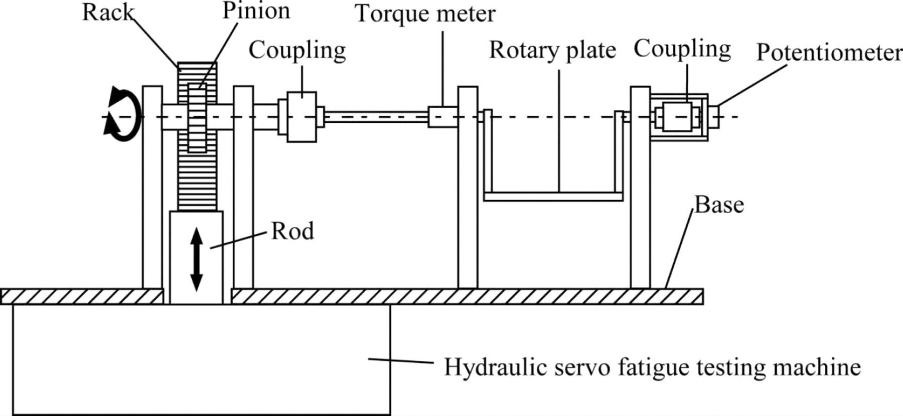
Schematic drawing of the automatic AAFO stiffness measurement device. The device was composed of a potentiometer, a torque meter, and a rotary plate. It was automated by a hydraulic servo fatigue testing machine and its reciprocal linear motion was converted to rotational one via a rack-pinion mechanism.
Experimental procedures
The amplitude and frequency of the rod of the hydraulic servo fatigue testing machine were tuned so that data acquisition could be conducted in the range from 15° plantarflexion to 15° dorsiflexion at an angular velocity of 10°/s. The range was determined as a reasonable estimate of typical deflection of an AAFO when worn during ambulation 29 and not designed to replicate walking in an AAFO because the angles would differ between patients and
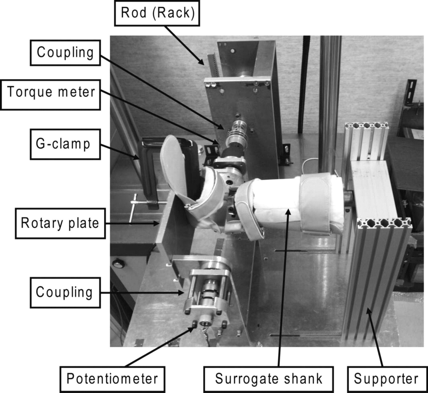
Fixation of the AAFO to the device. The AAFO was fixed to the device by clamping the footplate to the rotary plate using a G-clamp and fixing the prosthetic pylon of the surrogate shank to the supporter.
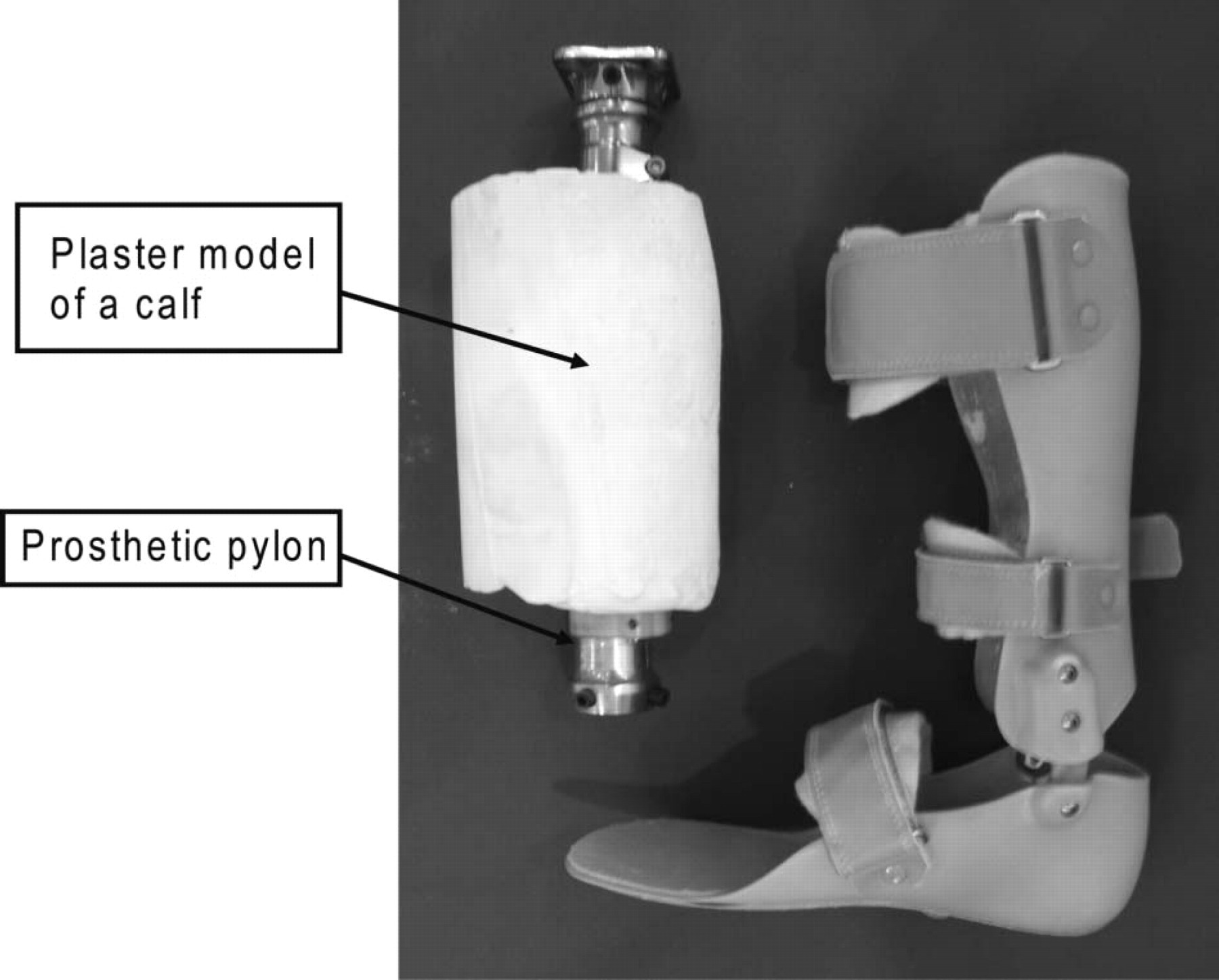
The plastic AAFO with Tamarack Variable Assist joints (right) and its surrogate shank (left). The surrogate shank was composed of a prosthetic pylon which penetrated through the plaster model of the calf.
AAFO designs. The resistive torque of the Tamarack Variable Assist joints was tuned to a minimum during the experiment. Since it has been reported that angular velocity does not affect the stiffness of a thermoplastic AFO, 24,25 the data collected at an angular velocity of 10°/s was presented in this study. The data collection was conducted at the sampling frequency of 200 Hz.
Data analysis
Further analysis of the data of a single trial, which consisted of seven cycles of measurements, was conducted. The collected data were filtered with a second order Butterworth low pass filter with a cut-off frequency at 2 Hz. The AAFO angle-torque data were plotted to obtain a hysteresis loop which consisted of two limbs, the ascending limb for plantarflexion direction movement and the descending limb for dorsiflexion direction movement (Figure 4).
The data in the ascending limb from 14° dorsiflexion to 14° plantarflexion were extracted and a third-order regression curve was plotted to obtain the torques corresponding to every 1° angular change. The ascending limbs of three hysteresis loops (2nd to 4th cycles of measurements) were averaged to produce one representative ascending limb of the hysteresis loop. 30 Stiffness of the AAFO was calculated by taking a slope at every 1° interval of each ascending limb of the hysteresis loop.
Validity test of the device
In order to validate the measured torque by the developed device, a simple experiment using a force gauge was conducted. The AAFO was, firstly, fixed to the developed device at 0° position in the measurement system (Figure 2) and a horizontal straight line was drawn on the AAFO as a reference line. The AAFO was then clamped using a G-clamp on the flat surface of a bench via a footplate (Figure 5).
A push-pull force gauge (Model 9500 series, Aikoh Engineering, Japan) was hooked at the upper brim of the AAFO. The force was applied via the force gauge until the reference line on the AAFO coincided with the plumb line in order to keep the 0° position (Figure 5). The applied force was measured five times and averaged.
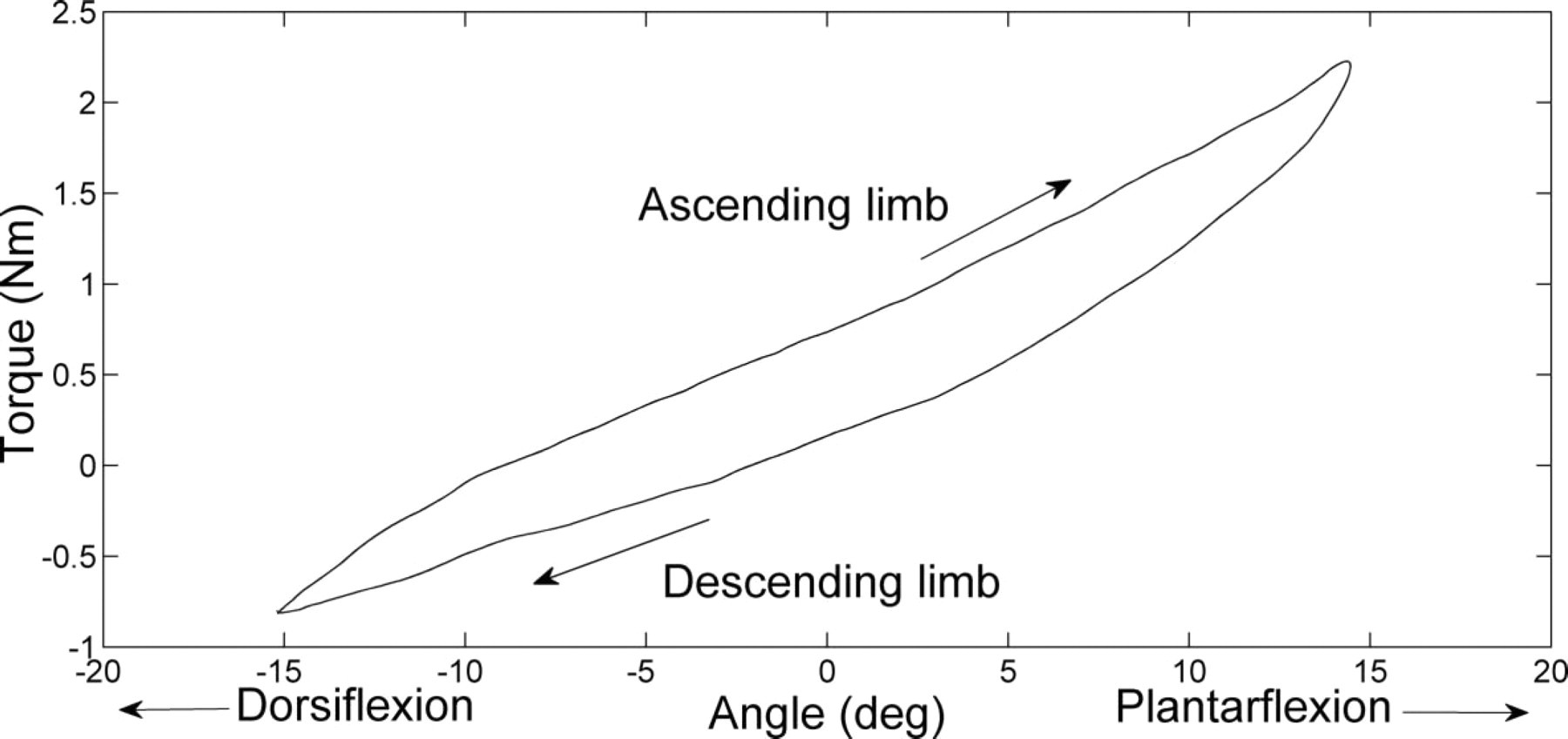
An example of an AAFO angle-torque hysteresis loop which consists of an ascending limb and a descending limb in a single cycle. The ascending limb from 14° dorsiflexion to 14° plantarflexion were extracted for further analysis.
The moment arm was measured using a digital height gauge (Model 192-651, Mitsutoyo, Japan) on the flat surface. The moment arm was calculated by subtracting the height of the joint centre from the height of the position of the applied force. The measurement of height was also conducted for five times and averaged. The resistive torque at 0° was calculated by multiplying the averaged force and moment arm.
Results
Range of motion and angular velocity of the rotary plate
Dorsi- and plantarflexion angle of the rotary plate as a function of time is shown in Figure 6. The actual range of motion of the rotary plate was from 15.2° dorsiflexion to 14.4° plantarflexion and the angular velocity was 9.9°/s.
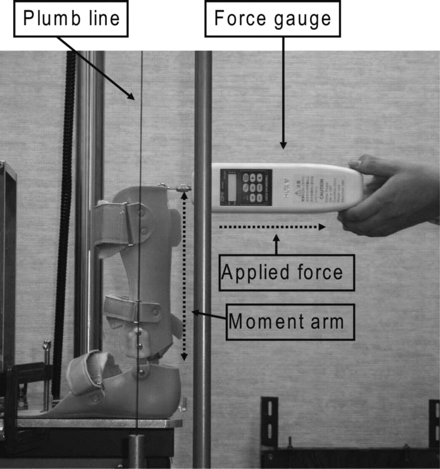
Measurement of plantarflexion resistive torque at 0° using a force gauge. The AAFO was fixed to the flat surface using a G-clamp. The force was applied via the force gauge until the reference line on the AAFO coincides with the plumb line in order to keep the 0° position.
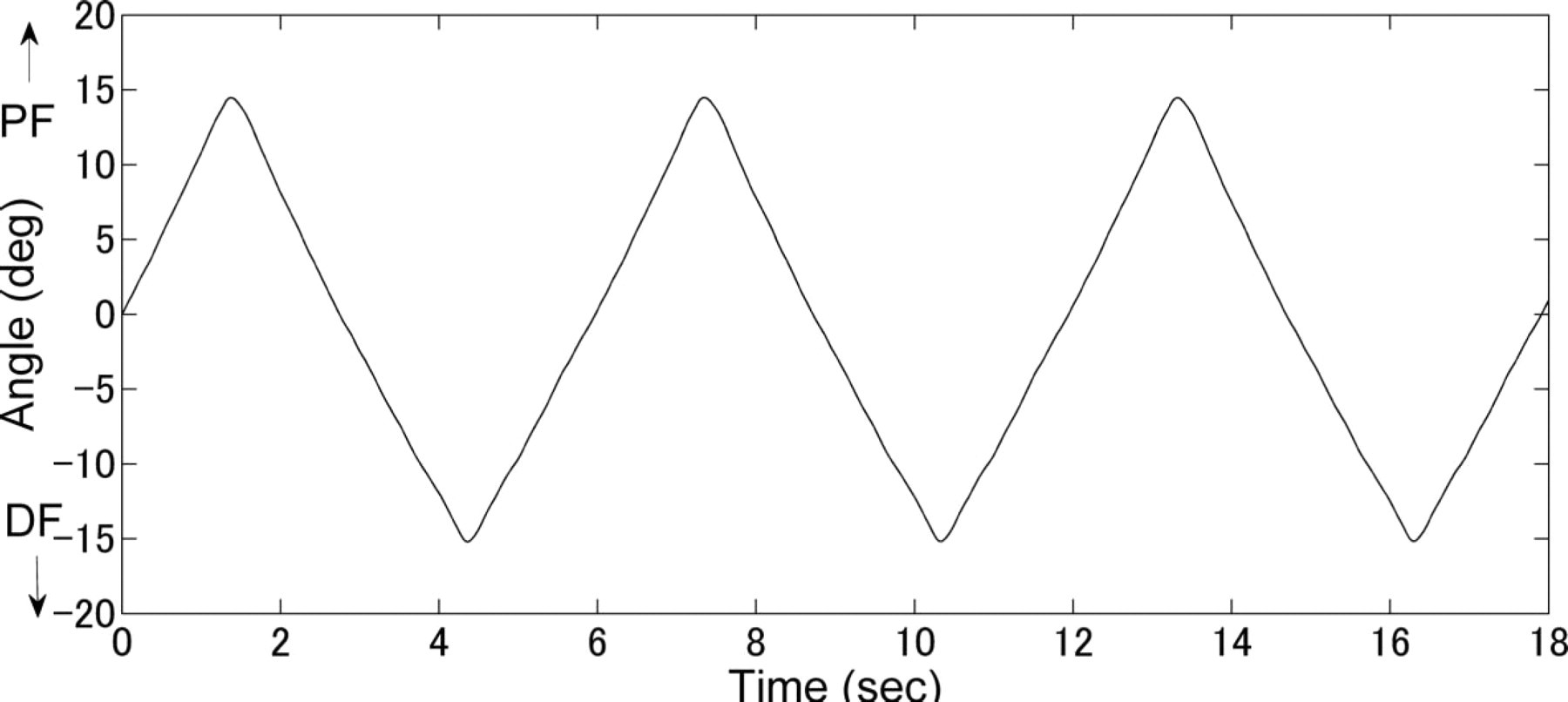
Dorsi- and plantarflexion angle of the rotary plate as a function of time. PF: plantarflexion, DF: dorsiflexion.
The calculated angle-torque relationship of the AAFO
The averaged ascending limbs of the AAFO angle-torque hysteresis loops in the range from 14° dorsiflexion to 14° plantarflexion is shown with standard deviations in Figure 7. It demonstrated an excellent correlation with a coefficient of determination (R2) of 0.99. The averaged torque ranged from −0.59±0.03 to 2.19±0.03 Nm in the range from 14° dorsiflexion to 14° plantarflexion.
The stiffness of the AAFO
The averaged AAFO stiffness-angle curve is shown in Figure 8. It ranged from 0.073±0.001 to 0.131±0.001 Nm/°.
Measurement of plantarflexion resistive torque of the AAFO at 0° position using the force gauge
The averaged applied force was 3.140±0.013 N and the averaged moment arm was 226.0±0.5 mm. Thus, the generated plantarflexion resistive torque at the 0° position was calculated as 0.690±0.005 Nm.
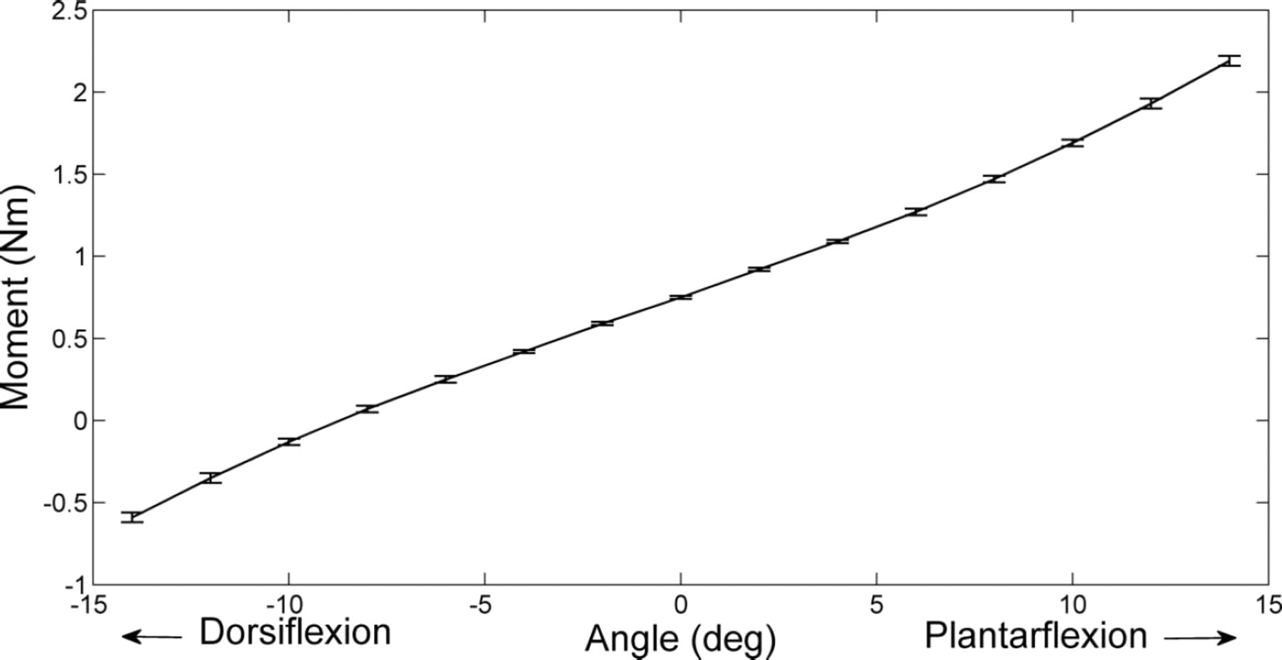
The averaged ascending limbs of the AAFO angle-torque hysteresis loops with standard deviations.
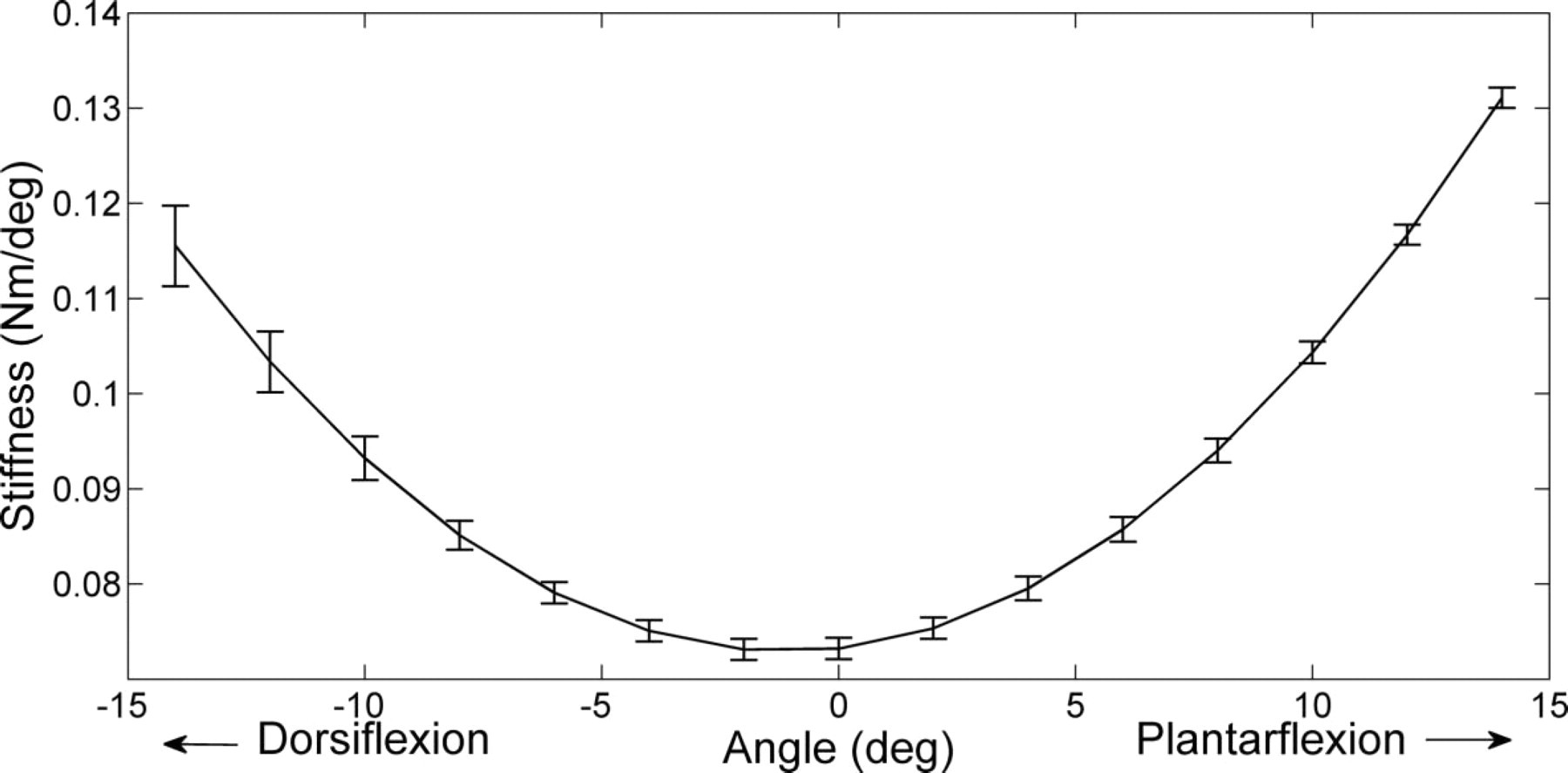
The averaged stiffness of the AAFO with standard deviations.
Discussion
A torque meter enables accurate and simple positioning of the rotational centre of an AAFO and direct measurement of its torque: therefore, it was considered suitable for the present device. The device was also designed to fix the AAFO in a non-destructive manner. The desired range of motion of the device for this experiment was 30° (−15° to 15°) and the desired angular velocity was 10°/s. The actual range of motion was 29.6° (−15.2° to 14.4°) and the actual angular velocity was 9.9°/s. The device was therefore able to perform within an accuracy of 4% and 1% to the range of motion and angular velocity envelopes respectively under the testing condition in this study.
The plantarflexion resistive torque at 0° in the measurement system using the force gauge showed that the AAFO generated 0.69 Nm of plantarflexion resistive torque, whilst that using the newly developed device was 0.75 Nm. Therefore, the accuracy of the measured torque was within 8% at the 0° position. However, this difference in the measurement was expected due to variations in experimental conditions including the method of force application and fixation of the AAFO. Moreover, the hysteresis and non-linearity of the torque meter were reported by the manufacturer to be 0.44% and 0.32% of the rated output of 22 Nm, respectively. Thus, the maximum error of 0.17 Nm would be expected to originate from the torque meter itself. In addition, considering the stiffness of the AAFO, torque cell hysteresis of the AAFO may have influenced the measured torque in this study.
The aim of designing the device was to enable measurement of the sagittal plane stiffness of an AAFO prescribed for a patient with hemiplegia. Fatone et al. (2009) demonstrated that the range of motion of the ankle joint of a patient with stroke hemiplegia walking with an AAFO was between 10° of dorsiflexion to 5° of plantarflexion. 29 Yamamoto et al. (1980) measured 11 types of AFOs and showed that, between 15° dorsiflexion and 20° plantarflexion, the moments generated by a typical AFO were within 20 Nm. 25 The rated output of the torquemeter of the device used in this study was 22 Nm. Therefore, the device should be able to cover the range of angle and moment of a typical AAFO for a patient with stroke hemiplegia. Naito et al. (2009) quantified the stiffness of a novel magnetorheological-fluid AFO joint using the present device in the approximate range from 20° dorsiflexion to 20° plantarflexon under the angular velocity ranging from 1–56°/s and revealed that its resistive torque varied from 1–8 Nm depending on its resistance setting. 31 The results of their study would support the use of the present device to test the stiffness of new AAFOs.
Functional analysis may be preferred as a more realistic measurement. However, the individual variability of force acting on an AFO during ambulation is large and is not well documented. Therefore, the ability to provide controlled cyclic testing using the present device could be valuable. It is the intention to clarify the external forces acting on the AAFO during gait in a future study and further develop the device to more accurately simulate dynamic loading to inform clinical AAFO prescription.
In this study, a linear fatigue testing machine rather than a simple gear motor was used to provide cyclic rotary motion for the stiffness test as the device could also perform fatigue resistance testing of an AAFO. The ISO structural test standard for an AFO has not been established. Although a muscle training machine 25 would also allow a simple measurement of the stiffness around the specific rotational centre of an AAFO, it would not be suitable for a fatigue test, which requires stable cyclic performance for a long period of time. Therefore, it is our intention to measure fatigue resistance of an AAFO in a future study.
The AAFO was fixed to the device via a surrogate shank which was made of a prosthetic pylon and a stiff plaster calf model. The surrogate shank could be re-designed to function as a pseudo-lower limb by including an appropriately-aligned ankle joint and with a surface
finish more akin to human tissue which would more closely emulate its viscoelastic properties.
The limitations of the study are as follows. Firstly, the testing was performed with a single angular range and angular velocity setting. Therefore, additional experiments are necessary to investigate if the reported performance errors are static (e.g., 0.6° and 0.1°/s) or scaling (e.g., 4% of range of motion and 1% of angular velocity). Secondly, although the device was rated for 22 Nm, it was tested to about 10% of that capacity because the AAFO tested in this study turned out to be very flexible. In order to verify its capability under more typical torque values of an AAFO, it needs to be tested with various AAFOs. Thirdly, the validity test of the measured torque was only conducted at the 0° position. It will be necessary to conduct the test at various angular positions to further validate the accuracy of the device. Finally, reproducibility analyses of the device by mounting/de-mounting AAFOs should be conducted in a future study.
Currently, it is not easy to provide the most appropriate AAFO to a patient because it is difficult to determine exactly how flexible it should be. Information obtained from the device developed in this study would help orthotists to understand the stiffness of an AAFO design. Quantification of the stiffness of an AAFO would assist them to provide a more rational prescription of an AAFO. Moreover, the device would also contribute to the quality assurance of an AAFO by assisting the assessment of whether a manufactured AAFO would meet the required stiffness and durability.
Conclusion
The aim of this study was to design a new automatic AAFO stiffness measurement device. It was demonstrated that the device was able to perform within an accuracy of 4% and 1% to the desired range of motion and angular velocity respectively under the testing conditions in this study. Measurement of the resistive torque at 0° using the force gauge showed the accuracy of the torque measured by the device to be within 8% at the 0° position. The device will be a useful quantitative tool for both orthotists and manufacturers.
Acknowledgements
The work was funded by the Hong Kong Polytechnic University Postgraduate Scholarships for PhD Studies and the Research fund of the Hyogo Prefectural Government.