
Abstract
In this research, a new type of binary material, a polyurethane-based warp-knitted spacer fabric composite (PWSF), having a unique three-dimensional structure, high strength, and a variety of surface structures was prepared. The compression meso-mechanics theoretical model based on the Winkler elastic foundation beam theory and structural parameters of PWSF were used to predict the compression performance of PWSF. To verify the validity of compression model, the compression stress-strain curves of theoretical simulation were compared with the quasi-static compression test results. The deviation between these two compression moduli was less than 7%. The compression meso-mechanics model established in this study can effectively simulate the actual compression behaviors for different PWSF specimens. A regular pattern of compression properties of this novel composite from the theoretical research on meso-mechanics perspectives can be proposed.
Keywords
Introduction
Recently, textiles are commonly used as alternative low-cost reinforcement for structural applications, such as automotive, packaging, building products, furniture, and consumer goods. 1 Various applications are demanding complex-shaped fabrics to meet the requirements of such domains. 2 Warp-knit spacer fabric composites exhibit greater drapability and anti-compression capacities as compared to other textile-reinforced composites. All of these advantages give warp-knit spacer fabrics great potential to be used for the reinforcement of composites.
There have been many studies on the compressive properties of warp-knit spacer fabric reinforced composites. Velosa et al. 3 studied some effect factors (i.e., cross-thread density, fineness of yarns, and face structure of fabrics, as well as fabric thickness) on the mechanical behaviors (compression and low-velocity impact responses) of novel sandwich composite panels made of 3D-knit spacer fabrics. Thermoplastic composites based on flat warp-knit 3D multilayer spacer fabrics were introduced by Abounaim. 4 The mechanical responses of these composites were significantly influenced by the arrangement of reinforced yarns; the integration of reinforced yarns with biaxial inlays were found to be the optimum method. Vuure et al. 5 developed a unit-cell model of core properties of composite panels based on spacer fabrics, and finite element method calculations of the compression responses of these novel composites were performed.
Thermoplastic composites based on flat warp-knit 3D multilayer spacer fabrics were introduced by Abounaim. 6 It can be concluded from their studies that the mechanical responses of these composites are significantly influenced by the arrangement of reinforced yarns. Furthermore, the integration of reinforced yarns with biaxial inlays provide the optimal method. The structural parameters of spacer fabrics are usually mentioned as important factors that can significantly influence the compression properties of composites.
In our previous research, a new type of flexible composite, polyurethane-based warp-knit spacer fabric composites (PWSF) was introduced. Furthermore, the quasi-static compression performance and low-velocity impact responses of these composites were studied.7,8 The findings indicate that the fabric structural parameters had a strong influence on the compression responses of 3D-structure composites. Additionally, the impact test carried out on the 3D-structure composites shows that the impact loads do not affect the integrity of composite structure. The product exhibits promising mechanical performance and its service life can be sustained.
However, in published research,9-11 the compression behavior of composites reinforced by warp-knit spacer fabrics were examined only on a macro-perspective. The mechanism of warp-knit spacer fabrics on the mechanical properties of the resulting composites is not clear, which limits its development. Thus, to understand the mechanical properties of PWSF, and then achieve controllable preparation of PWSF, it is necessary to analyze the mechanical properties of PWSF from the meso-mechanics aspect. For these reasons, establishing the compression meso-mechanics theoretical model of PWSF to predict mechanical properties is important.
In this study, we establish a compression meso-mechanics theoretical model for different PWSF specimens based on Winkler's elastic foundation beam theory. Additionally, the structural parameters of composites (e.g., the number of lapping movements of spacer yarns, surface structure, and spacer yarn's diameter and thickness) are involved in the model. The theoretical results were then compared with the experimental value to verify the validity of the compression meso-mechanics model. It is hoped that the research results can provide the basis for choosing the appropriate structural parameters of composites under different application conditions.
Experimental
Warp-Knit Spacer Fabrics and Specimen Preparation
The warp-knit spacer fabrics were provided by Wuyang Co. Ltd., Jiangsu, China. Fig. 1 shows the basic structure of 18-gauge double-needle-bar Raschel warp knitting machine and the schematic illustration of warp-knit spacer fabrics. The front guide bars (GB5 and GB6) knit a surface layer fabric on the front needle bar only, while the back bars (GB1 and GB2) knit the other separate surface layer fabric on the back needle bar. The middle bars (GB3 and GB4) carry the spacer yarns and knit on both needle bars in succession to connect two outer layers. Meanwhile, the surface layer structure (Chain+Inlay) and side view of spacer yarns are illustrated in Figs. 2a and b, while the SEM images of polyurethane foam are presented in Figs. 2c and d. The real view and schematic diagram of produced composites are shown in Figs. 2e and f. 12 The polyurethane material used in this paper is soft polyurethane foam (BASF, PuDong Site, Shanghai, China), which is polymerized by polyol and isocyanate. At 23 °C, polyols and isocyanates were foamed in the reaction of M (polyols): m (isocyanates) = 100:43.7, with a moderate foaming rate and uniform foaming. The distance between the upper and lower surfaces of the mold can be adjusted according to the thickness of the spacer fabric. In the preparation process, the distance between the upper and lower surfaces of the mold can be adjusted to the same thickness as the spacer fabric, and the upper and lower surfaces of the mold can be heated by a water bath to accelerate the curing process of the polyurethane foam. The details of the four types of polyurethane-based composites used in this study are provided in Table I and Fig. 3.
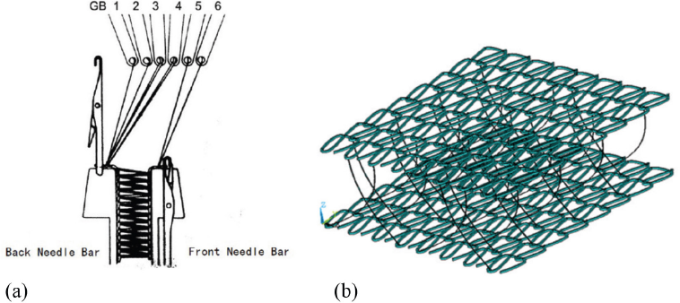
(a) Model of double-needle-bar warp knitting machine (used under CC BY-NC-ND 4.0) and (b) schematic illustration of warp-knit spacer fabrics.
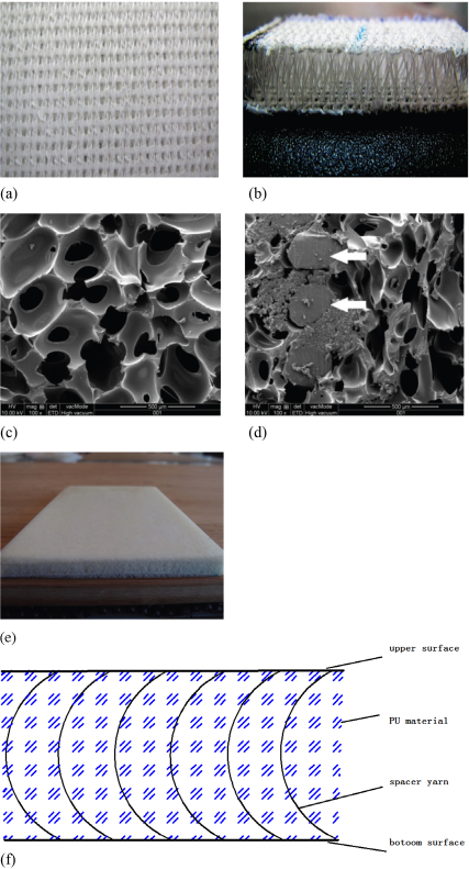
(a) Surface layer structures (Chain+Inlay), (b) side view of spacer yarns, (c) SEM images of polyurethane foam, (d) x-y plane cross section of composite (The arrows in b indicate the spacer yarns in composite), (e) the real view, and (f) schematic diagram of PWSFC.
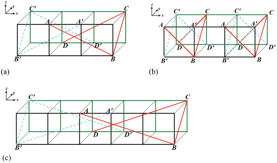
The global arrangement of spacer yarns (a) type I, (b) type II, and (c) type III. The red line represents the spacer yarns made by GB3, while the blue lines are spacer yarns made by GB4.
Structural Parameters of Polyurethane-Based Composites
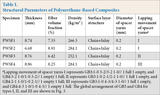
Lapping movement of spacer yarns I represents GB3:1-0 3-2/3-2 1-0// 1 full 1 empty, and GB4:3-2 1-0/1-0 3-2// 1 empty 1 full; II represents GB3:1-0 2-1/2-1 1-0// 1 full 1 empty, and GB4:2-1 1-0/1-0 2-1// 1 empty 1 full; III represents GB3:1-0 4-3/4-3 1-0// 1 full 1 empty, and GB4:4-3 1-0/1-0 4-3// 1 empty 1 full. The global arrangement of GB3 and GB4 for types I, II, and III are shown in Fig. 3.
Quasi-Static Compression Experiment
The compression tests were conducted using a Shanghai HL WDW Series material test instrument, and testing was done at 23 °C and 65% relative humidity (RH) based on the Chinese standard GB/T8168-2008. 13 The compression plate is a circle of 60-mm diameter. The specimens were pressed to a deformation that was 60% of the initial thickness at a load speed of 1 mm/min and five repeats were carried out for each specimen. The compression experimental process is given in the literature.8,12
Modelling
The foundation beam is placed on the elastic foundation, and the load is applied on the foundation beam. The foundation beam deforms together with the elastic foundation under the load. Therefore, a reaction force is produced on the surface of the foundation beam with the elastic foundation. The magnitude of the reaction force is closely related to the displacement of the elastic foundation deformation. Obviously, the larger the deformation displacement is, the greater the reaction force is. Therefore, how to determine the relationship between the reaction force of the elastic foundation and the deformation displacement of the foundation is the key to calculating the stress of the elastic foundation beam. This is the general application of the Winkler foundation model in the engineering area. 14
The Winkler foundation model treats the elastic foundation as multiple, but independent, force springs. When a point on the surface of the elastic foundation is subjected to a compression load, the deformation displacement only occurs in the local range of the force point, and does not occur in other places. A foundation material with mechanical properties similar to that of a liquid, such as a material with lower shear strength, is more consistent with the assumption of the Winkler type foundation model.15,16
During the compression process, the main deformation is the spacer yarns in the spacer zone, and the composite panel can be regarded as a rigid body that does not deform in the compression process. Therefore, the spatial periodic distribution characteristics and the geometric parameters of spacer yarns play a decisive role in the mechanical properties of composites. In this study, the polyurethane foam in the composite material can be regarded as an elastic foundation, while the spacer yarns are regarded as a beam element distributed in different elastic foundation. Because of the great difference between polyurethane foam and spacer yarns, the spacer yarns are the main force unit when the composites are subjected to a compression load. The polyurethane foam plays a supporting and limiting role on the spacer yarns. The distributed load is the reaction force exerted by the polyurethane foam on the spacer yarns, and the displacement of the spacer yarns at each point is the same as that of the polyurethane foam.
Based on the above, the meso-mechanics theoretical compression model based on the Winkler elastic foundation beam theory was established. Additionally, the structural parameters of PWSF were used to predict the compression responses. The polyurethane foam in this composite can be regarded as an elastic foundation, while the spacer yarns are regarded as a beam element distributed in the elastic foundation. Because of the large difference between the compression modulus of polyurethane foam and spacer yarns, the spacer yarns are the main load carrier when the composite is subjected to compression force. The polyurethane foam plays a supporting and limiting role to the spacer yarns. The distributed load is the reaction force exerted by the polyurethane foam on the spacer yarns. Thus, the displacement of the spacer yarns at each point is the same as that of the polyurethane foam.
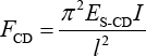
The minimum unit of composites is shown in Fig. 4, where lines CB and CD represent the spacer yarns. According to Fig. 4, the total compression force
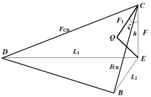
The decomposition of the compression force at point C on the BCD plane.
The perpendicularity line EQ of BCD plane is made through point E, CE represents the compressive force
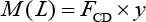
Based on the tetrahedron volume and the Helen equation, the relationship between the total compression force

According to the above, as long as the compression force on the spacer yarns CB and CD is obtained, the component force
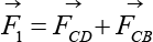
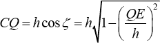
Compression Force on Spacer Yarns CB
A bar with a curve axis can be regarded as a curved bar. Thus, according to the actual appearance of the spacer yarns, spacer yarns CB is seen as a curved bar. The curved bar studied in this research has the following restrictions: the curved bar has a longitudinal symmetry plane and the cross section has a symmetry axis.
When the loads focus on the longitudinal symmetry plane of the curved bar, the internal force on the cross section can be divided into the axial force
Stress condition of curved rod.
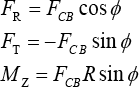
Taking two boundary conditions of bending moment (
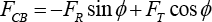
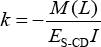
The force corresponding to the axial force
Taking Eq. 6 into Eq. 5, then Eq. 7 can be obtained as follows:
The value of
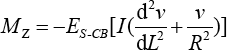
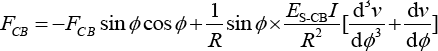
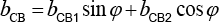
Polyurethane foam is regarded as the superposition of two Winkler elastic foundation beams. The reaction force from the foam is divided into two directions: horizontal and vertical. The elastic foundation coefficient of polyurethane foam
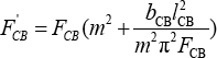
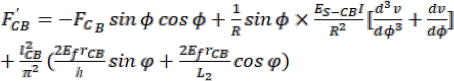
The compression force
Compression Force on Spacer Yarns CD
According to the actual appearance of the spacer yarns, spacer yarns CD is regarded as the compression bar. The schematic of spacer yarns CD during the compression process is shown in Fig. 6, where solid and dotted lines represent the shape of spacer yarns before and after suffering compression force, respectively,
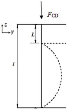
The compression principle of spacer CD.
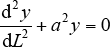
It is assumed that spacer yarns CD is a compression bar hinged at both ends. According to the analysis of its stress during the compression process, the component force on spacer yarns CD is far less than the critical force of spacer yarns CD, so the deformation of the spacer yarns CD during the compression process can be regarded as a small deflection deformation. 18 The deflection differential formula can be expressed in Eqs. 11 and 12.
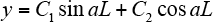
C1 and C2 are the general solution of the deflection equation.
Considering the boundary conditions
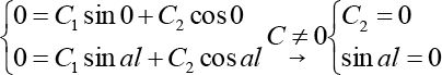
In Eq. 13, if
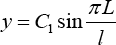
According to Eq. 13, it can be seen that a = π/
As a compression bar element, its vertical length
And the curvature of a plane curve is expressed in Eq. 17.
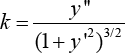
By combining Eqs. 14, 15, and 17, Eqs. 18 and 19 can be obtained.
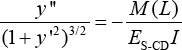
Similarly, the compression force F'CD on the spacer yarns CD, taking into consideration the reaction force from the foam, can be obtained as shown in Eq. 20.
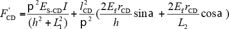
lCD is the length of spacer yarns CD (mm),
The compression force on spacer yarns CB and CD can be obtained by Eqs. 10 and 20, and then the total compression force

However, several other structural parameters are needed to predict the meso-mechanics compression behaviors of PWSE The calculation process of structural parameters is as follows. The spatial arrangement of spacer yarns formed by GB3 in PWSF1 is selected to calculate the unknown structural parameters. The spacer yarns formed by guide bar GB3 in one under-lapped are shown in Fig. 7. According to Fig. 7, on the AD'BC plane, the angle between the spacer yarns AB and the bottom surface is α, while on the BC'CB' plane, the angle between the spacer yarns CB and the bottom surface is ϕ. The horizontal distance across the spacer yarns AB is 2B, while the horizontal distance across the spacer yarns CB is 0, as the horizontal distance across the spacer yarns CD is 2B. The longitudinal span of the spacer yarns AB is 0, the longitudinal span of the spacer yarns CB is L2, and the longitudinal span of the spacer yarns CD is 0.

The arrangement of spacer yarns by Guide Bar 3. (a) The lapping movement of spacer yarns and (b) the model of spacer yarns.
The stress area (

The calculated results of the relevant structural parameters are shown in Table II. Based on the compression test results of spacer fabric, the values of the radius of curvature and the angle of curvature center (ϕ) of the intermediate spacer yarns CB at the strain of 0%-60% were recorded and are given in Table III. According to Table III, the curvature radius reduction value (
The Calculated Structural Parameters of PWSF a
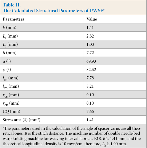
The parameters used in the calculation of the angle of spacer yarns are all theoretical ones.
Radius and Angle of Curvature for Spacer Yarns CB
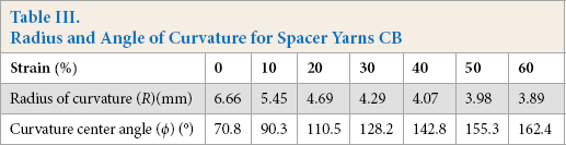
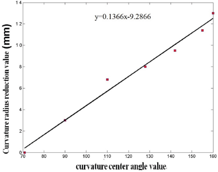
The curve of curvature radius reduction value (
Experimental Verification
Substituting the calculated structural parameters into Eq. 3, the theoretical compression stress-strain curves and compression modulus can be obtained, as shown in Fig. 9. To compare theoretical and test results, the experimental compression stress-strain curves and compression modulus obtained in our previous study 8 are also given in Fig. 9. The results show that the compression responses were obviously influenced by the structural parameters of PWSF. The theoretical and experimental results had a high degree of agreement. Deviation between these four compression moduli were 3.03%, 6.89%, 5.31%, and 6.56%, respectively.
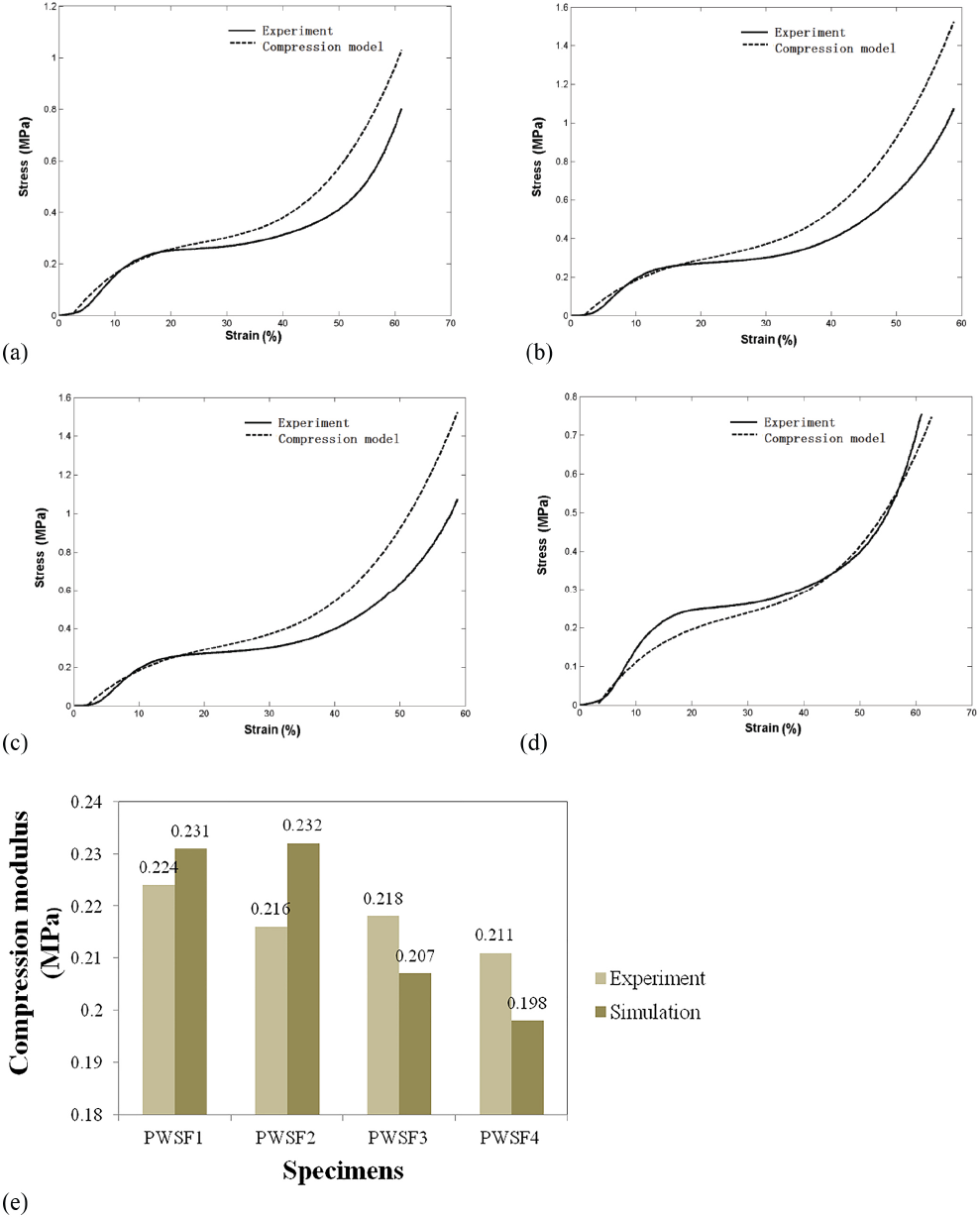
Comparison of experimental and simulation compression stress-strain curves and compression modulus for PWSF. (a) Experimental and simulation compression stress-strain curves for PWSF1, (b) experimental and simulation compression stress-strain curves for PWSF2, (c) experimental and simulation compression stress-strain curves for PWSF3, (d) experimental and simulation compression stress-strain curves for PWSF4, and (e) experimental and simulation compression modulus for PWSF.
The compression meso-mechanics model established in this study can effectively simulate the actual compression behaviors for various PWSF specimens. However, there were still some deviations between these two curves. The main reasons for the phenomenon are as follows.
Model Simplification
In the process of building the compression model, a unit with the minimum cycle was selected for analysis, and the cells were independent when suffering force loads, so there was no interaction between the cells. In the actual compression process, there is coupling effect between cells, which will cause mutual extrusion and friction, thus affecting the deformation of materials under compression stress.
Differences between Actual and Theoretical Parameters
When calculating the angle between the spacer yarns and the bottom, the model regards the spacer yarns as a straight bar to calculate the angle. But the spacer yarns (especially the spacer yarns CB) were not completely vertical, which changes the angle. The distance
Measurement Deviation
It is necessary to measure
Neglect of Horizontal Forces
In this model, it is assumed that in the process of compression, there is only a large bending deformation in the vertical direction, but no relative displacement in the horizontal direction, and there is no friction between the spacer yarns and the polyurethane foam. If these forces are ignored, there will be some deviations between the theoretical and test result curves.
Conclusion
The compression meso-mechanics theoretical model based on Winkler elastic foundation beam theory and structural parameters of PWSF was used to predict the compression performance of PWSF. Based on the model, the composite structure and parameters (i.e., the arrangement of spacer yarns by the spacer bar, the diameter of the spacer yarns, the thickness of the material, and the radius and angle of curvature for spacer yarns) were used to simulate the theoretical compression curves of the composites. Then, the simulated results were compared with the values obtained from quasi-static compression tests. The findings show that the deviation between these two compression stress-strain curves was less than 7%, indicating good consistency between predicted and experimental results. The compression meso-mechanics model established in this study can effectively simulate the actual compression properties for various PWSF specimens. However, there were still some deviations between these two curves. The main reason for this was the simplification of some structural parameters. In future studies, the structural parameters will be better specified to obtain accurate simulation results.
Footnotes
Acknowledgement
The authors acknowledge the financial support from the Inner Mongolia Natural Science Foundation (2020LH01005).