
Abstract
Axial compression properties of special-shaped 3D tubular woven composites with basalt fiber filament tows were studied. Special-shaped 3D tubular woven fabrics composites with three different thicknesses were woven on an ordinary loom and fabricated by the vacuum assisted resin transfer molding (VARTM) process. Load-displacement and energy-displacement curves were obtained from experimental tests. Results showed that for special-shaped 3D tubular woven composites, the load and energy absorption were greater with thickness and the compression property improved. Through the analysis of the mathematical equation and correlation coefficient of the load-displacement and energy-displacement relation, the fitting effect of the curves were good. The mathematical equation of the method could be used to simplify the functional relationship between load, energy, and displacement.
Introduction
3D tubular composite materials have excellent mechanical properties and structural advantages such as light weight, high specific stiffness and strength, excellent fatigue resistance, good corrosion resistance, and so on. Meanwhile, 3D tubular composite materials are structural members with reasonable stress forms. Closed tubular specimens can avoid the problem of uneven stress distribution at the free edge of plate-like specimens. 1
3D tubular woven composites, as a special textile structural material, are mainly used in the oil and natural gas industry due to the advantages of the mechanically uniform circular shape and the provided properties. 2 The 3D woven technique is superior in manufacturing the special-shaped 3D tubular preform. 3D woven composites have gained extensive attention for their high impact resistance and damage tolerance, low delamination, and structural integrity. Bilisik et al. 3 developed a 3D multiaxial circular woven fabric of a generally cylindrical shape, having a core defined therein about a central axis. Bilisik's et al. 4 research was to develop new preformed structures and processes for use in the textile and composite industries. Preliminary studies showed that the multi-axis 3D circular woven preforms and methods were feasible. In terms of weaving and design, the 3D tubular woven fabrics and other 3D woven fabrics studied by our research group also provide the basis for the weaving of the special-shaped 3D tubular woven fabrics in this study. 5
Carmisciano 6 comparatively studied the mechanical properties of basalt fiber and alkali-free glass fiber woven fabric reinforced composites. The results showed that basalt fiber composites had a higher flexural modulus and interlaminar shear strength. Basalt fiber, as a fiber with excellent environmental protection performance, will be studied in more depth in future research.
Chen et al. 7 designed the knitting die and process for 3D aramid fiber knitted fabric, and determined the best knitting process. However, due to the complexity and high cost of knitting technology, it is not suitable for mass production. Due to the variability of knitted fabrics, there is less research on 3D tubular composites.
Wang et al. 8 studied the microstructure of 3D four-way braided tubular composites and proposed a modeling method based on free from deformation (FFD) theory. This model not only solves the problem of yarn overlapping, but also accurately describes the key characteristics of the preform. Zhang et al. 9 invented a new type of 3D fully integrated multi-layer tubular fabric, which can eliminate delamination, and studied the axial impact compression performance of a 3D overall multi-layer tubular fabric reinforced carbon/epoxy composite tube. The results showed that the selection of winding yarn is more important in improving the axial compression strength. Although the 3D tubular braided composites have good properties, the research is still limited due to the difficulty in popularizing weaving machines and the high cost.
Zhu et al. 10 respectively made triangular, rhombus, square, and round-like 3D porous tubular structures. The research results provided technical support for the structural design and manufacture of multi-row porous tubular textiles. Wang et al. 11 took angle linkage as the basic weave structure of the fabric, and wove 1500D aramid filament into an integrally-formed four-layer tubular fabric. Tensile tests under the same conditions showed that the mechanical properties of the prepared composite tubular material were significantly improved compared with that of plain woven fabric wound into a tubular composite material. Bilisik et al. 12 developed various 3D circular woven preforms. Data generated from these structures included yarn-to-yarn space, density, yarn angle, yarn length, and crimp. It was shown that the weave patterns affected the 3D circular woven preform structures. These studies provided new ideas for testing the mechanical properties of special-shaped 3D tubular composites.
In terms of raw material selection, carbon, Kevlar, and glass fibers are mainly used in the preparation of composite materials. However, compared with these fibers, basalt fibers have the characteristics of high strength, high modulus, high temperature resistance, compression strength, shear strength, and especially good environmental protection.13-15 Many studies on basalt fiber reinforced composites have been done previously. 16 But few studies have been done on 3D tubular woven composites with basalt fibers.
Experimental
Materials and Equipment
Epoxy vinyl resin (V-118) from Wuxi Qianguang Chemical Co. Ltd. was used as a matrix. Basalt fiber filaments tows (800 tex) from Zhejiang Shijin Basalt Fiber Co. Ltd. were chosen as weft and warp yarns. A loom in the lab (SGA 598) from Tongyuan Textile Machinery Co. Ltd. was used for weaving small samples. The VARTM molding system was used for molding, the prototype of a general system (QG-5A) from the Shanghai Caya Industry Co. Ltd. was used for sample cutting, and a universal testing machine (TH-8102S) from Suzhou Tober Machinery Co. Ltd. was used for testing.
Weaving of Special-Shaped 3D Tubular Woven Fabric
The specific weaving sketch of the special-shaped 3D tubular woven fabric is shown in Fig. 1. The shape and structure of A1 and A3 were the same, so A1 and A3 were given the same weaving structure. The same warp yarn structure diagram and chain drafting were used to weave the structures of A1 and A3. A2 was different from A1 and A3 in shape and structure, so a different warp yarn structure diagram and chain drafting were used to weave the A2 structure. The length of A1 was equal to A3 (25 mm) and the diameter of A2 was 50 mm.
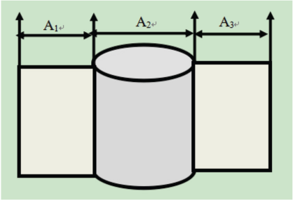
Specific weaving sketch of special-shaped 3D tubular woven fabric.
Special-shaped 3D tubular woven fabrics with three different thicknesses were designed. The warp structural drawings of the special-shaped 3D tubular woven fabrics with three different thicknesses are shown in Figs. 2–4. 17 According to the warp structural drawings, the chain drafts of special-shaped 3D tubular woven fabrics with three different thicknesses were drawn, as shown in Figs. 5–7. 18 The fabric on and under the loom is shown in Fig. 8.
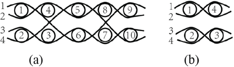
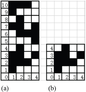
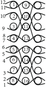
Warp structural drawings of special-shaped 3D tubular woven fabrics with thickness of 1 mm. The line is warp yarn and the circle is weft yarn. (a) Warp structural drawings of A1 or A3 and (b) warp structural drawings of A2.
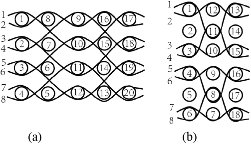
Warp structural drawings of special-shaped 3D tubular woven fabrics with thickness of 2 mm. The line is warp yarn and the circle is weft yarn. (a) Warp structural drawings of A1 or A3 and (b) warp structural drawings of A2.
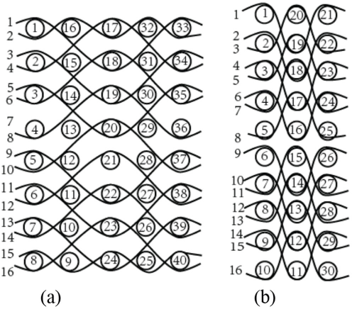
Warp structural drawings of special-shaped 3D tubular woven fabrics with thickness of 4 mm. The line is warp yarn and the circle is weft yarn. (a) Warp structural drawings of A1 or A3 and (b) warp structural drawings of A2.
Chain drafts of special-shaped 3D tubular woven fabrics with thickness of 1 mm. The black squares are warp interlacing point and the white squares are weft interlacing point, the numbers in the vertical direction are weft numbers and numbers in the horizontal direction are warp numbers. (a) Chain drafts of A1 or A3 and (b) chain drafts of A2.
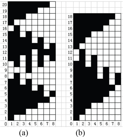
Chain drafts of special-shaped 3D tubular woven fabrics with thickness of 2 mm. The black squares are warp interlacing point and the white squares are weft interlacing point, the numbers in the vertical direction are weft numbers and numbers in the horizontal direction are warp numbers. (a) Chain drafts of A1 or A3 and (b) chain drafts of A2.
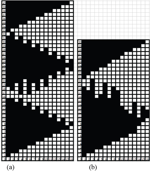
Chain drafts of special-shaped 3D tubular woven fabrics with thickness of 4 mm. The black squares are warp interlacing point and the white squares are weft interlacing point, the numbers in the vertical direction are weft numbers and numbers in the horizontal direction are warp numbers. (a) Chain drafts of A1 or A3 and (b) chain drafts of A2.
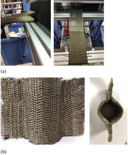
Weaving diagram of special-shaped 3D tubular woven fabric. (a) Fabric on loom and (b) finished fabric.
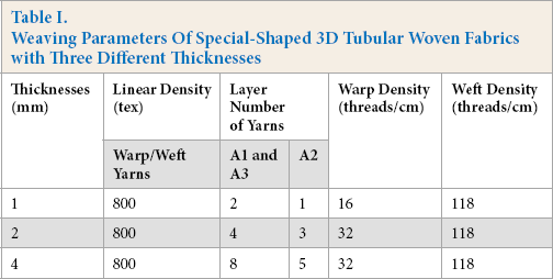
The weaving parameters of special-shaped 3D tubular woven fabrics with three different thicknesses are shown in Table I.
Weaving Parameters Of Special-Shaped 3D Tubular Woven Fabrics with Tree Different Thicknesses
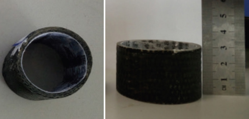
The special-shaped 3D tubular woven composites were manufactured by the VARTM process. To maintain the hollowness of the fabric, we adopted a self-made mold as shown in Fig. 9, which was made of paraffin, which melts at 75 °C. The role of the VARTM process principle and the structure of each part is available in the literature. 19 The proportion of epoxy vinyl resin, curing agent, and accelerating agent was 100:5:5. As shown in Fig. 10, the special-shaped 3D tubular woven composites were cut to a test height of 30 mm. The thickness of special-shaped 3D tubular woven composites were 1, 2, and 4 mm, respectively. The thickness of A1 or A3 was twice that of the wall of A2.
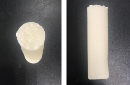
Pictures of paraffin mold.
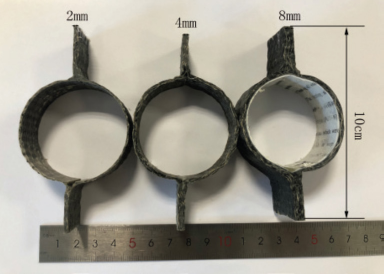
Pictures of the special-shaped 3D tubular woven composites with three different thicknesses.
Characterization of Special-Shaped 3D Tubular Woven Composites
The testing of axial compression was according to GB/T 5350-2005 20 using a universal testing machine (TH-8102S). The testing speed was 10 mm/min. Fig. 11 is a schematic diagram of the beginning and the end of the compression experiment.
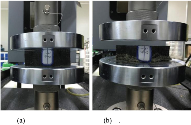
Schematic diagram of the compression experiment (a) at the beginning and (b) at the end.
In this study, the energy absorption properties were evaluated by energy-displacement scatter plots, which were obtained by integrating the area of the load-displacement scatter plots curves in Origin 8.5.
Origin 8.5 Polynomial Fitting
Although the test process of compression test was relatively simple, the amount of data to be measured in the experiment was large and the processing of experimental data was relatively complicated. The best method for data processing was the least square method, which could accurately ft curves linearly or non-linearly. However, the amount of calculation was large and complicated, and it was difficult to realize manual calculation through numerous formulas. Origin 8.5 software only used the least square method to carry out polynomial fitting on the data according to the load-displacement and energy-displacement scatter plots, and has been adopted by many scholars. 21
Comparison with a Regular Tubular Woven Composite
As shown in Figs. 12 and 13, the warp structural drawings and chain drafts of the regular tubular woven fabric had a thickness of 4 mm and a diameter of 50 mm.
Warp structural drawings of regular tubular woven fabric with thickness of 4 mm.

Chain drafts of regular tubular woven fabric with thickness of 4 mm.
Fig. 14 shows pictures of the regular 3D tubular woven composite with a thickness of 4 mm. The raw materials of the regular tubular composite were the same as that of the special-shaped 3D tubular composite, both of which were manufactured with the VARTM process and compressed in the same way.
Pictures of the special-shaped 3D tubular woven composites with thickness of 4 mm.
Results and Discussion
Load-Displacement Curves
The axial compression properties of the special-shaped 3D tubular woven composites were evaluated by load-displacement and energy-displacement scatter plots. By fitting the load-displacement scatter plot many times, the ninth-order polynomial fitting method was adopted. The load-displacement scatter plot was obtained from experimental data and then fitted by the least square method using Origin 8.5. There were three specimens of each structure used in the compression test, and the curve with the best compression performance was selected for polynomial fitting. The correlation coefficient values of different specimens of the same structure were different. The load-displacement scatter plot and fitting curves of the special-shaped 3D tubular woven composites with three different thicknesses are shown in Fig. 15.
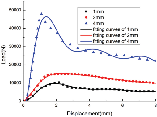
Load-displacement scatter plots and fitting curves of special-shaped 3D tubular woven composites with three different thicknesses.
The polynomial fitting formulas were then obtained by calculation of the least square method in Origin 8.5. The mathematical equation of fitting curves and correlation coefficient of the load-displacement relationship are shown in Table II. From the correlation coefficient in Table II, the fitting effect of the curve was good. The fitting results depended on the correlation coefficient R. The value range of R was 0 ≤ R ≤ 1. Setting the R value to 1 gave a more consistent curve and formula. This mathematical equation of the fitting curve can be used to simplify the functional relationship between load and displacement.
Mathematical Equation of Fitting Curve and Correlation Coefficient of Load-Displacement Relationship
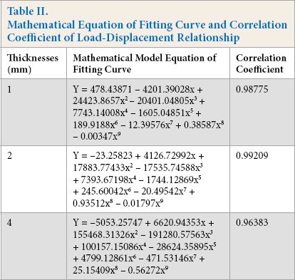
Fig. 15 shows that the load increases with the increased composite thickness. Composite thickness had a significant impact on its load, indicating that the compression performance was sensitive to the composite thickness. Analysis of Fig. 15 showed that all three fitting curves were divided into three stages. At the beginning, the fitting curve was almost linear, which indicated that the resin and fiber bonded well, so the composite material showed linear elastic properties. The pressure plate dropped at a constant speed, and the sample made a slight crackling sound, with no obvious resin damage on the surface of the composite material. With increased displacement, the slope of the curve decreased. With the increased displacement between the sample and the pressure plate, the pressure plate continued to decline. The sample made a clear crackling sound, and cracks appeared on the surface of the composite material. The curve was no longer straight, the resin began to break, and finally, from the peak value, the curve began to decline rapidly. The composite material began to shear, and the composite material deformation was serious. But there was no fracture.
Energy-Displacement Curves
In this study, energy-displacement scatter plots were obtained from the experimental data. By observing the energy-displacement scatter plots, the fourth-order polynomial fitting method was adopted, and the least square fitting method was used with Origin 8.5. The energy-displacement scatter plot and fitting curve of the three different thicknesses of special-shaped 3D tubular woven composite are shown in Fig. 16.
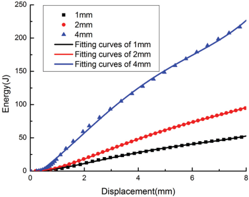
Energy-displacement scatter plots and fitting curves of special-shaped 3D tubular woven composites with three different thicknesses.
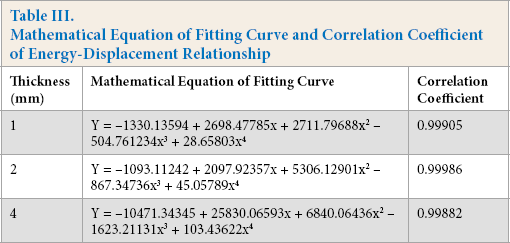
The mathematical model equation of the fitting curves and the correlation coefficient of the load-displacement relationship are shown in Table III. The correlation coefficients of the three curves were all close to 1, so the curve fitting effect was good. From Fig. 16, the energy absorption value increased with increased thickness of the special-shaped 3D tubular woven composite. The compression and energy absorption performance of the special-shaped 3D tubular woven composite were proportional to each other.
Mathematical Equation of Fitting Curve and Correlation Coefficient of Energy-Displacement Relationship
Energy absorption was an important index of cushioning performance and impact resistance of the composite materials during compression. The cushioning performance and compression resistance of the special-shaped 3D tubular woven composites increased with increased thickness.
Comparison Curve
The load-displacement comparison curve of the regular tubular woven composite and special-shaped 3D tubular woven composite (4 mm in diameter) is shown in Fig. 17. The maximum displacement load of the special-shaped 3D tubular woven composite was higher than that of the regular tubular woven composite. The energy displacement comparison curve between the regular tubular woven composite and the special-shaped 3D tubular woven composite is shown in Fig. 18. The energy absorption value of the special-shaped 3D tubular woven composite was higher than that of the regular tubular woven composite. The results showed that the compression performance of the special-shaped 3D tubular woven composite were better than that of the regular tubular woven composite.
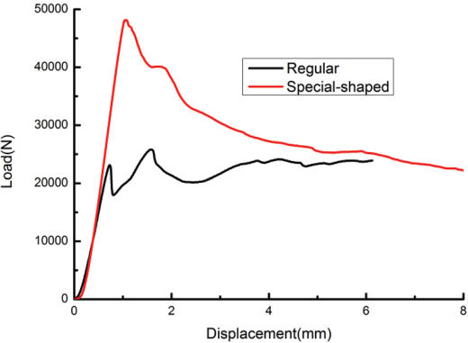
Load-displacement comparison curve of regular tubular woven composite and special-shaped 3D tubular woven composite.
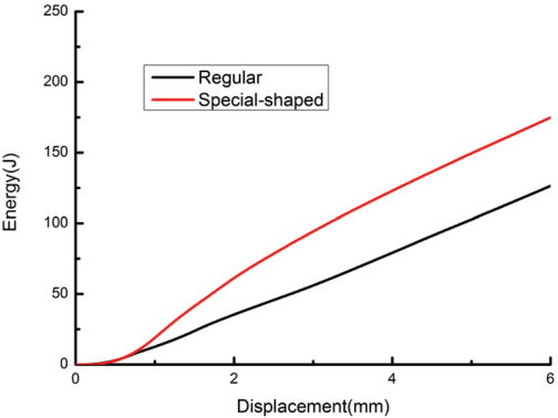
Energy-displacement comparison curve between the regular tubular woven composite and the special-shaped 3D tubular woven composite.
Failure Mode and Mechanism
The failure mode and mechanism of special-shaped 3D tubular woven composites with different thicknesses were similar. Therefore, only the special-shaped 3D tubular woven composite material with 4-mm thickness was used as an example. The failure photographs of this material are shown in Fig. 19.
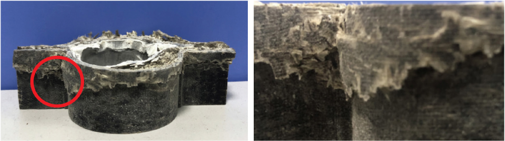
Failure mode photographs of special-shaped 3D tubular woven composites with the thickness of 4 mm.
The axial compression failure mode showed obvious shear failure. At the beginning of axial compression, the change of the material surface was not obvious, the compression load changed linearly with increased displacement, and the energy absorption curve increased gradually. With further increased compression, the fiber bundle buckled in some areas, causing shear failure of the matrix, and then basic fracture. With further increase in the degree of buckling, the fiber had large tensile deformation and fracture, which led to the maximum energy absorption value of the fold on the surface of the tube. However, due to the support of other fibers, the whole fiber remained intact after the compression failure.
With the increase in the thickness of the special-shaped 3D tubular woven composite, the compression resistance of the composite became stronger, but there was no delamination in the damage process of the special-shaped 3D tubular woven composite. The special-shaped 3D tubular woven composites had high delamination resistance. The transverse crack of special-shaped 3D tubular woven composite was mainly caused by the low fracture toughness of the epoxy resin.
Conclusions
From the results of this study, the following conclusions were drawn. The special-shaped 3D tubular woven fabrics with three different thicknesses can be woven on an ordinary loom by reasonable design with low cost. The special-shaped 3D tubular woven composites with a thickness of 4 mm had a maximum load and energy absorption value, the special-shaped 3D tubular woven composite material with a thickness of 1 mm had a minimum load and energy absorption value, and the special-shaped 3D tubular woven composite with a thickness of 2 mm had load and energy absorption values in between. With the increase of the thickness, the compression properties of the special-shaped 3D tubular woven composites increased. At the same thickness, the compression properties of the special-shaped 3D tubular woven composites were better than that of the regular tubular woven composites.
Through the analysis of Origin 8.5 fitting results, the polynomial fitting formula could be obtained by the calculation of least square method in Origin 8.5. The mathematical equation of the method could be used to simplify the functional relationship between load, energy, and displacement, which was convenient for engineering applications.
The special-shaped 3D tubular woven composites had excellent mechanical properties. During the test, the composite material showed good compressive strength without delamination and splitting. The thickness of the special-shaped 3D tubular woven composite used as the reinforced composite material was different. The compression performance was also very different, but all had the same failure mode and failure mechanism.
Footnotes
Acknowledgments
The author(s) disclosed receipt of the following financial support for the research, authorship, and/or publication of this article. The authors gratefully acknowledge financial support from the National Science Foundation of Liaoning Province (2019-MS-017) and the Technological Innovation Team Project of Liaoning Province (LT2017017).