
Abstract
The focus of this study is on strain sensing research and applications in smart textiles. Strain sensing is the measurement of fabric deformation by embedding a strain-sensitive material in it and subjecting it to stress. This paper presents an extensive classification of knitted textile strain sensors. Salient knitted strain sensor production parameters, such as conductive yarn choice, fabric structure, fabric structure deformation, and its relationship to strain signal extraction are discussed. The study concludes that producing yarn-based soft strain sensors for smart textile applications is viable. However, sensitive yarns with the right conductivity, count, and structural configuration are often unavailable. Work remains in the areas of efficient fabric deformation, signal extraction methods, development of sensor nodes, and robust experimental testing systems.
Introduction
The cravings for “smart everything” has entered the sphere of textiles, making the smart textile applications we see in blockbuster movies now a reality. Currently, baby monitors, health shirts, sports bras and vests, air conditioning suits (warming and cooling), and massage bras are in vogue. Smart functionalities in apparel are varied and are developed based on different technologies and theories. The chief technologies include optics/infrared sensing, LEDs, GPS, electrical conduction, thermal conduction, bio-sensing (sweat sensing), ultrasonics, photochromism, and strain sensing.
However, applying these technologies to implement soft and inherent smart textile functionalities are difficult due to material incompatibilities. The electronic components usually applied are rigid, not washable, expensive, and lack good aesthetic appeal in some cases. 1 The ideal textile-based sensing structures needs to be flexible, fit closely to the human body, be lightweight, and provide wearer's comfort during long-term use. 2 The lack of technology for inherent integration of textile-compatible electronics with high functionality is impeding a major breakthrough in wearable smart-apparel production.
Strain-sensing technology can be embedded into textiles while retaining the properties of the bulk textile. Typically, strain in an object is measured or sensed using a strain gauge. 3 Strain sensing in smart textiles can be described as the measurement of fabric deformation of fabric embedded with a strain-sensitive material after subjecting it to stress.
Textile strain sensors can be classified into four broad, largely mutually inclusive categories, namely, mode of manufacture, textile ornamentation sensing, sensing technology, and sensitivity trigger based methods. The mode of manufacture based category encompasses sensors fabricated using textile construction methods such as knitting, 4 weaving, 5 braiding,6,7 and film/composite based. 8 Textile decoration or ornamentation methods, such as stitching (overlock and embroidery),9,10 printing, and coating/bonding/past-ing 11 can also be used. The sensitivity trigger based category includes components that induce the strain or effectuate the sensitivity of the sensors. These include properties such as temperature, weight, stretch, and so forth. A piezoresistive or inductive humidity strain sensor can therefore be printed, stitched, or coated on a woven, knitted, or braided fabric.
Sensing technologies based methods include piezoresistive sensing, 12 resistive sensing, 13 piezoelectricity, 14 impedance, 15 capacitance,16-18 inductance, 19 and fiber optics (Fresnel reflection 20 and fiber Bragg grating21,22). Recent developments, such as the use of piezotronics, 23 and photoelastic strain sensing, 24 have also been cited in the literature. The piezoresistive effect allows an analog electrical resistance signal to be extracted based on the principle that electrically-conductive wires will respond to changes in resistance when subjected to stress. Resistive sensors operate by sensing the change in the structural configuration of the sensitive area when subjected to stress. The sensitive area is designed by separating conductive zones with resistive elements or setting up overlapping nano-materials within a percolation network (a lattice constructed of a random mixture of conducting and nonconducting links). As voltage is applied across the area of the sensor, subsequent application of stress activates or deactivates the conductivity of the sensor, which is measured relative to the induced stress.
Impedance is a measure of the electrical resistance and reactance that a circuit presents when voltage is applied. The resistance component arises from the collisions of the current carrying charged particles within the internal structure of the conductor. The reactance component is the additional opposition to the movement of electrical charge arising from the changing magnetic and electrical fields in the circuit carrying alternating current. Capacitance-based sensors measure sensitivity through the variation of capacitance induced by the change of the distance between two opposing electrodes, the overlapped area of the electrodes, or the relative dielectric constant. 25
With inductance, when an alternating current is passed through a coil of wire, an alternating magnetic field is generated that surrounds it. Another coil situated within this field will have an alternating current induced in it. The magnitude of the induced current is proportional to the magnetic field density, which in turn, is nonlinearly related to the distance between the two coils. Thus, a pair of sending and receiving coils provides a non-contacting displacement measure for strain. 26
Piezoelectricity defines the ability of certain materials to generate an electrical charge in response to applied mechanical stress or vice versa. 27 Whereas in fiber optics, deformation of the optical fiber leads to changes in phase/intensity/ wavelength depending on the specific sensing mechanism being used. Fiber optics describes the medium and the technology related to the transmission of information as light pulses along a glass or plastic strand or fiber. Photoelasticity describes changes in the optical properties of a material under mechanical deformation. The piezotronic effect is the use of the inner crystal potential generated by piezoelectric polarization charges for controlling/tuning the charge carrier transport characteristics in some materials that simultaneously exhibit piezoelectric, semiconducting, and photo-excitation properties. 28
The mutual inclusivity between these categories is expressed as a distinguishing factor or permutation and is illustrated in detail in Fig. 1. Examples include piezoresistive knitted strain sensors, piezoelectric woven strain sensors, printed piezoelectric strain sensors, and so forth. The choice of a particular sensing technology defines the kind of materials needed, including testing instruments, and even the type of textile fabrication method.
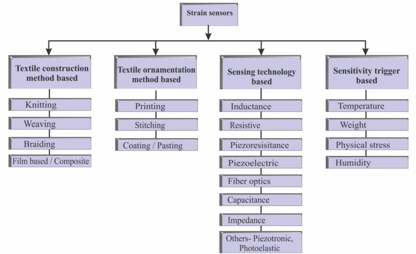
Block diagrammatic classification of strain sensors.
A couple of reviews have been published on smart textiles and intelligent clothing, as well as e-textiles (electronic textiles) and wearable textiles.29-32 This paper, however, will focus on strain and soft sensor engineered smart textile applications based on piezoresistive sensitive yarns.
This review highlights the further need for strain sensor research. Problems that strain sensor research were intended to resolve, proffered solutions, and outstanding issues going forward, are reviewed. The foregoing discussions present issues focused on weaving and knitting based strain sensor implementation. Salient strain sensor parameters, such as yarn characteristics and fabric structures, are discussed. Also covered are prototyping and applications of piezoresistive strain sensors. loop configurations, and their relationship with strain signal extraction.
Strain Sensor Implementation
Although the success of soft, ornamentation based, strain sensors are established,1,33,34 the focus of this study is on the sensitivity derived from woven or knitted fabricated sensors. This is directly based on the fibers within the fabric structure. Also, this study covers wearable smart textiles. Fiber-based fabrication of apparel can lend itself to advanced knitting technology that affords seamless, full garment manufacture. This reduces the manufacturing process to a single-step process. Furthermore, some of the fabric ornamentation and composite fabrication methods are performed after a fabric has been produced through weaving or knitting, thereby raising production cost issues. The importance of developing sensitivity or smartness of textiles through the yarns themselves cannot be overemphasized.
The two dominant modes of fabric construction are knitting and weaving. 35 Weaving is a method of textile production in which two distinct sets of yarns or threads are interlaced at right angles on a loom to form a fabric or cloth. Woven structures are characterized by high inextensibility, 36 a characteristic that makes them unfavorable for strain sensing. Also, the conductive yarns currently available for fabricating strain sensors cannot endure the weaving tensions that yarns are subjected to and are likely to break during weaving. What is usually done is to use woven fabrics as substrates onto which fabric decoration methods such as printing, stitching, and pasting are applied to effect strain sensing.32,37
Some researchers have attempted to directly weave strain sensors into the fabric structure. Kannaian et al. 38 developed an elastomeric tape sensor using polyester yarns as base threads and rubber thread yarns as an elastomer for sensor development. Using a narrow-width tape loom, silver-coated nylon yarns were introduced in the middle of the tape structure during the weaving process. Notwithstanding these attempts, weaving continues to play a minor role compared to knitting in soft strain sensor manufacture.
Knitting is the preferred choice for strain sensor fabrication. Some unusually coarse conductive wire, which may not be weavable, may be suitable for knitting. Stress on yarns during knitting is limited compared to weaving, thereby enhancing the knittability of delicate conductive yarns. This is enhanced by the use of electronic yarn feeders in modern knitting machines, which enables quick and efficient regulation of yarn tensile stress. 39 Advanced knitting machinery and enhanced design capabilities also ensure that the conductive sections can be inserted at desired locations, even in seamless garments. 40
Knitted structures possess superior flexibility,41-44 having a lower modulus of elasticity as compared to its woven coun-terparts.45,46 The modulus of elasticity is an indication of the relationship between stress and strain in the deformation of a solid body. It describes its stiffness and is therefore one of the most important properties of solid materials. This review will now focus on knitted piezoresistive and resistive sensors.
Yarn Characteristics
Of great importance is the type of conductive yarn used for sensor fabrication. In producing the strain sensor, conductive yarns are embedded within nonconductive structures at specified areas.
Several studies have reported on the production of sensitive yarns suitable for producing textile strain sensors. 47 However, most of these conductive yarns are not readily available on the market. Researchers have therefore relied on lab manufactured yarns, 48 commercial conductive wires/ filaments,4,49 and the few conductive yarns available com-mercially12,50 to integrate sensors into fabrics.
The conductive yarns used include carbon-coated polyester with polyester and elastic yarns, 51 silver-coated yarns,52-54 carbon fiber yarns, and stainless steel filaments. 51 Other proprietary yarns, such as Bekinox yarn (Zhengzhou LP Industry Co. Ltd.), which is composed of stainless steel fiber and polyester, Statex Shieldex silver-coated yarn (Statex Co.), and Beakart stainless steel and polyester yarn (NV Bekaert SA), exist. Silver plated/coated yarns have found the widest use. This may be due to its commercial availability, comparative suitability to the knitting process, and appreciable conductivity level. However, there have been issues about its reduced sensitivity after laundering. 55
Other yarns being used also have limitations. Stainless steel yarns currently available commercially are only in the form of monofilaments. These monofilaments are between 0.012 and 0.050 mm in diameter, too fine to be knitted on knitting machines. In one study, 51 275 filaments were used in knitting. Friction between the 275 filaments caused problems for the knitting machine and increased the internal friction in the fabric.
In an EU funded project entitled Wealthy, conductive fabric electrodes were prepared with a yarn spun using two stainless steel wires twisted around a viscose yarn. 56 Ehrmann et al. described the yarns used as S-shield made of staple silver fibers, and stainless steel yarn consisting of 20% stainless steel fibers and 80% polyester fibers. 57 Slippage occurred in wrapped yarns during sensitivity tests. Carbon fiber yarns exhibited poor bendability. 58
However, the non-conductive yarns also influenced the sensitivity of a sensor to a large extent. Incorporation of elastic non-conductive yarns into fabric structures is needed to enhance elasticity. Nonetheless, very extensible yarns, such as bare strand elastic yarns, tend to deliver reduced sensor sensitivity at small deformations due to enhanced conductive contacts within intermeshed structures. 59 This reduces the resistance of the sensor. Low resistance values generate sensor reliability problems as well as higher power consumption. Semi-elastic yarns, such as air textured and spandex core spun yarns or covered yarns, are therefore recommended for integration with conductive yarns for strain sensors with applications that require minimal deformations.
Apart from the yarn's individual characteristics, the quantity of conductive yarn embedded within the fabric structure can exhibit different, interesting dynamics on the sensing system. According to Cirio et al., 60 by increasing the number of courses of conductive yarn within the sensitive zone, there is a corresponding decrease in electrical resistance.
It is also clear that the appropriate conductive yarn for a strain sensor study must have an appropriate yarn count, flexibility, and external and internal configurations, to deliver a unidirectional piezoresistive response when stretched. Suitable yarn count is also dependent on the type of knitting machinery used; fat knitting machines usually favor coarse counts, while its circular counterparts are ideal for fine counts. The yarns must have homogenous external structure and the conductive path must be consistent.
Fabric Parameters and Piezoresistance Sensors
Sensor sensitivity, dimensional stability, and repeatability are influenced by fabric structure to a significant extent. Studies involving a number of fabric structures are cited in the literature, dominated by jersey structures as they are thought to possess better recovery. 61 The two most important characteristics when deciding on a fabric structure for strain sensors are recovery (or dimensional stability) and elasticity (or flexibil-ity). However, Atalay et al. contends that because the interlock structure has the highest dimensional stability among the basic weft-knitted structures, it is able to deliver a sensor with good repeatability. 62 Yan, who experimented on three mock rib structures, namely 1×1, 2×1, and 2×2, says that the resistance stability of 1×1 mock rib was the best, followed by 2×2 mock rib, with 2×1 mock rib producing unstable changes in resistance. 63 Other weft stitches such as float, ribs, and its variants are also reported. 64 There is, therefore, no general consensus on a suitable knitted fabric structure for strain sensor use.
Warp knitting has seen very few applications in knitted strain sensing. This may be due to the comparative limited use of warp-knitted fabrics in apparel. Convenience in production may also be the reason as, for example, a cone of conductive yarn and some non-conductive cones is all that might be needed to produce a strain sensor on a fat weft knitting machine. One study by Zhang et al. 58 compared single warp fabrics crocheted using a special needle by hand, and a tubular weft plain fabric knitted on a 12-needle hand circular knitting machine. The tubular weft fabrics tend to have poor recovery compared with the single warp sample; tubular fabrics have more contacting points and these contacting points caused larger internal friction compared to the single warp fabric. With the conductive yarns embedded into a chosen structure, structural analysis is required to establish the relationships between loops and to study the behavior of a physical structure when subjected to stress. Conventional analysis and design of textile structures are based on describing the fabric structure as a system of algebraic equations, and solving the system simultaneously by iteration.65,66
To appreciate the relationship between strain and the signal that is generated from it, it is proposed that strain or structural deformation in knits (course wise) is based on two premises, one, being deformation or bending of the loops and two, continued tension at the loop interconnects referred to as contact resistance. 58
The application of sufficient load causes the loops to change shape.67-69 Different fabric structures have unique strain-bearing configurations, which in turn have a bearing on resistance information extraction. Jersey fabrics under tensile stress behave such that the purl loops on the back side of a plain structure are the primary recipients of the load and buckle under the initial loading or stress. 68 With increased stress, the loop legs get elongated as a result of the arcs becoming longer. Subsequently, the interconnected points then begin to pull each other apart. The behavior of float stitches under mechanical stress have been well studied by Liu et al., who examined the influence of float stitches on piezoresistance using a geometric model. 70
With regards to rib knits, as tension is applied to the fabric in the course direction, the face loops begin to pull away, resulting in the emergence of vertical grooves as the reverse loop wales are exposed.
Depending on the external configuration of the yarn and the stress magnitude, the dominance of inter-yarn contact, commonly referred to as contact resistance, leads to decreases in resistance. The degrees of deformation and the magnitude of sensitive information generated, apart from fabric structure type, are dependent on important factors that are interrelat-ed—yarn type (both conductive and non-conductive), loop configuration within the structure (loop length and loop shape), and the direction and magnitude of stress.
Predicting the fabric's mechanical properties, such as strength, elongation, bending, and shear, is an intricate task36,71 as it requires complete understanding of the fabric's structural mechanics and the interaction among yarns in the structure. 36 These variables are responsible for the difficulties in establishing relationships between knitted structure and output signal generated. A number of modeling studies were done on knitted structures, which serves as an analogy to help visualize and calculate instances that cannot be directly observed.72-75 Loop circuit network models that explain deformation/resistance relationships in fabric structures have furthered the discourse on textile strain sensing.58,76
There is agreement among researchers that two resistance triggers, namely loop deformation and contact resistance, are responsible for the overall resistance of the sensing circuit network.58,76,77 A unit loop (Fig. 2) will essentially have five resistive points: loop head or arc resistance, two contact resistance points, and two loop leg resistance points. Differences in knit structure and the direction of tensile stress, however, determine which of the resistance types dominates overall sensitivity when the structure is subjected to stress. In loop models, such as where the conductive yarns occupy a distinct zone, the conductive circuit is likely to behave as if contact resistance dominates. 58
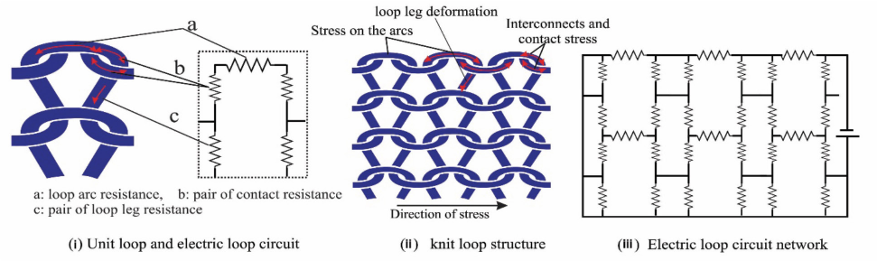
Schematic diagrams of knit loop and electric circuit network.
In knitted structures where conductive yarns are knitted together with elastic yarns, the sensitivity of the fabric structure or a change in resistance results due to the separation of the otherwise compact loop structures is observed. 78 This confirms the hypothesis that the sensing mechanism is important in determining strain sensor classification. Oks et al. knits the fabric using a plain stitch and the courses are formed, alternately isolating the conductive yarns. 76 The loops in their unstressed states are in contact with each other, therefore, upon subjecting them to stress, the contacts are interrupted. This leads to an increase in resistance upon stretching, and, unlike the other loop models, gives comparatively inferior contact resistance.
So far, only jersey fabrics have been extensively studied using loop network modeling. Other elaborate and complex mathematical methods, such as collision search and response algorithms, use penalty-based contact forces in yarn-yarn collisions. 79 Finite element analysis (FEA) 80 is used in an attempt to express the relationship between loop deformation and applied stress. These advanced simulation methods are, however, not widely applied in investigating piezoresistive response in conductive yarns. These algorithms could incorporate other salient parameters, like semi-conductive behavior of the conductive loops, which hitherto are ignored in the current mathematical methods. 58 It may also confirm or deny the suggestion that generation of piezoresistive signals from textile structures under tensile stress is based on stretching of the yarns along its axis, 51 which would justify the classification of such sensors as piezoresistive, or merely on deformation, which would imply that they are rather resistive sensors.
Strain Measurement Setups and Sensor Characterization
The important sensing performance parameters required of a strain sensor include, but are not limited to, high accuracy, good linearity, good repeatability, and a quick response time. 81 The accuracy measurements depend on accurate equipment and robust connections. One big challenge, however, is the lack of a standard instrument for measuring piezoresistive response or sensor characterization.
While there are several methods of measuring strain, the most common is with a strain gauge, a device where the electrical resistance varies in proportion to the amount of strain in the device. In the development of textile or soft strain sensors, several hybrid systems are used to measure strain and electrical resistance. 82
Most lab tensile strain tests are performed using classical tensile testers that stresses the samples at defined intervals and cycles. Custom-fitted data acquisition systems, such as micrometers, multimeters, voltage testers, earth resistance testers, and resistance testers,8,83 connect with the conductive terminals of the sample and measure alterations in resistance. A typical test set up is shown in Fig. 3. The ZwickRoell tensile tester (ZwickRoell GmbH & Co.) was fitted with a Wheatstone bridge analytical arrangement and experimental data recorded using TestXpert II software. 62
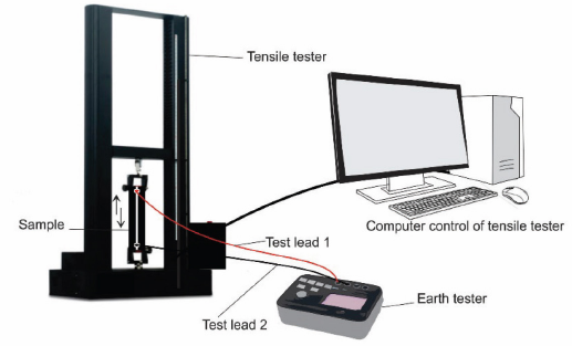
Typical fabric strain sensor test set up.
Multimeters usually apply a very small direct current to the strain sensor and measure the voltage drop across the resistance in ohms. This is the mode of operation for a typical two-wire test used in strain sensor research. The main issue with this two-wire test method is that, in instances of low resistance measurements, the total lead resistance is factored into the measurement. Because the test current causes a small, but significant voltage drop across the lead resistance, the voltage measured by the meter is not exactly the same as the voltage directly across the sensor, resulting in considerable error.
Typical lead resistance ranges from 10 mΩ to 1 Ω, making accurate two-wire resistance measurements difficult when the resistance of interest is less than 100 Ω. This is because the resistance of interest will be totally inundated by the lead resistance. 84
Four-wire resistance measurement is the most accurate way to measure very small resistances using multimeters. The current and voltage are applied in two separate circuits, also called the source and the sense circuits. With this configura-tion, the test current is forced through the test resistance via one set of test leads (source leads), while the voltage across the strain sensor is measured through a second set of leads (sense leads).
Although some limited current may flow through the sense leads, it is usually insignificant and can generally be ignored for all practical purposes. Therefore, the voltage measured by the meter is essentially the same as the voltage across the resistance. As a result, the resistance value can be derived much more accurately with the four-wire method. Also the voltage-sensing leads should be connected as close to the sensor being tested as possible to forestall adding part of the resistance of the test leads in the measurement.
It is instructive to note that the current sole reliance on multimeters and earth testers, most especially in the two-wire tests used in many studies, is an over-simplification of the strain sensor characterization process. Theoretically, upon stretching, the woven or knitted piezoresistive sensor must respond to stress linearly either by increasing or decreasing resistance. This is, however, simplistic, as the electrical resistance measured in these experiments is affected by many factors and conditions. These factors include the internal configurations of yarns within the structure, 85 contact resistance between yarns and environmental conditions, and so forth. Conductive materials (e.g., yarn and probes) used, surface cleanliness, temperature, humidity, and elec-trification time, among other factors, also affect resistance readings. Any contamination, oxidation, or surface irregularities can compromise the results of a test.
Piezoresistive sensors are, therefore, fraught with a great deal of noise and signal non-linearity. 86 Designing custom signal processing systems (SoCs) to help filter out noise is one way of ensuring efficient deformation signal extraction. These systems are usually composed of a power management unit, a sensor analogue front end (AFE), a digital signal processor, a signal transmission system, and a display.
A sensor interface circuit may require a biasing circuit, an amplifier, comparators, a digital to analog convertor (DAC), analog multiplexers, voltage references, a filter network for noise suppression, error suppression techniques (e.g., offset removal), and an analog to digital converter (ADC) to digitize and process the sensor data. 87 These custom systems must be designed with their target applications in mind. They must be small enough and be equipped with, for example, wireless data transmission functionality to provide convenience in ambulatory test situations.
Strain Sensor Sensitivity
The gage factor (GF) is originally used for measuring sensitivity in classical strain gauges. Strain-sensor researchers have adopted GF values for correlating strain and resistance by characterizing strain sensors. GF values are used as a standard for ascertaining sensitivity in textile strains sensor design and development studies. 88 GF is defined as the ratio of fractional change in electrical resistance to the fractional change in length (strain) in Eq. 1.
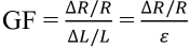
A sensor with a greater GF value is more sensitive than one with a smaller GF value. 89 Several studies have referred the sensitivity of their strain sensors to the gauge factor, but the values ascribed to this quantity are quite varied. One study 90 reported GF values between 0.06 to 0.82 for their carbon nanotube strain sensors. Another study 91 reported GF values as high as 103.
Therefore, it is very difficult, if not impossible, to ascertain the real sensitivity of these various sensors and make meaningful comparisons. Table I shows various GF values reported from various studies. The absence of a standard for sensitivity based on GF values makes it a non-ideal unit to describe the actual sensitivity of textile sensors.
Tensile Test Results of Sensosr
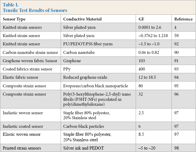
Computations of the sensitivity index (GF) relies on the type of conductive or sensitive material, the fabric structure, and the initial resistance of the sensor; the higher the initial resistance, the higher the sensitivity. This explains why the study by Xue et al. 93 involving polypyrrole (PPy) and polyurethane (PU) coated conductive yarns yielded a high GF value of 400. The initial resistances of the PPy and PU coated conductive yarns were 100-200 and 200-300 kΩ, respectively.
The GF value is influenced to a great extent by the type of conductive material used in fabricating the particular strain sensor and also the sensing mechanism. Negative GF values are indicative of strain sensors that exhibit reduction in resistance upon deformation, while those with positive values exhibit the opposite response. The use of GF values in describing the sensitivity of textile sensors should therefore be considered, bearing in mind the fabrication methods and materials used, as well as the magnitude of stress applied.
Response Time
Response time is defined as the interval required by the output signal of a sensor to display a change in the applied strain. In the literature, it has been described as time taken for the output signal to reach either 63.2% or 90% 86 of the actual change from the time the input change occurs. Response time is frequently confused with the time constant, which describes the mechanical and electronic response time of linear systems. The use of either response time or time constant might be influenced by the linearity (or non-linearity) of the sensor. Time constants are more suitable for 1st order systems, while 2nd or higher order systems favor response time. What has been referred to as response time86,99 in some strain sensor reports are essentially time constants. Strain sensor time constants cited in literature include 30 ms for a capacitive, soft-strain sensor), 99 200 ms for AgNWs-PDMS (silver nanowire-polydimethylsiloxane), 100 and 140 ms for ZnONWs (zinc oxide nanowires)-polysty-rene 101 were recorded for composite-based resistive-type strain sensors. Most studies on knitted strain sensors do not report response time and its computation to characterize their sensors, even though this parameter is very important, especially in characterizing sensors for breath monitoring applications where deformations and recoveries are time bound.
Hysteresis
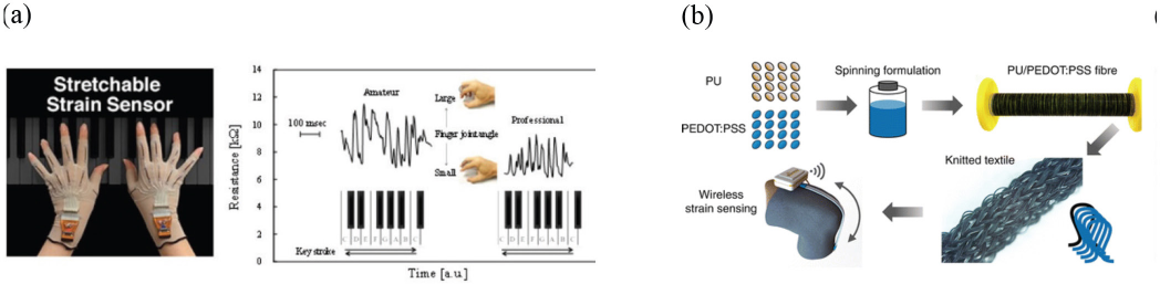
A hysteresis error is described as the deviation of the sensor's output at a specified point of the input signal when it is approached from opposite directions. In reality, most materials deviate from Hooke's law in various ways, for example, by exhibiting viscous-like as well as elastic characteristics. In textile structures, this is also induced by the random distribution of fibers during stress recovery. 102 The hysteresis error can be calculated using Eq. 2.
δ
Hysteresis adversely affects resistance values of sensors by causing fluctuations in resistance during cyclic tests. This, of course, may also be influenced by the nature of textile structures and other environmental factors. Atalay et al. 59 ascribe it to the duality of their structure, which caused dimensional instability during tensile test. Other imput-able causes include friction by structural alteration in a conductive fabric due to deformation of fibers and slippage between fibers, as well as stretching, bending, twisting, and compressing effects activated when the knitted fabric is stretched. 103 However, according to Zhang et al., 102 high fabric density reduces hysteresis, due to smaller configura-tion changes under stress.
Prototyping and Applications of Strain Sensors in Smart Textiles
Integration of strain sensors into apparel is approached in various ways by different researchers. This includes whole body posture measurement, which enables a qualitative and quantitative measurement of exercise conduction in fit-ness training and rehabilitation. The areas of strain sensor application include, but are not limited to, physiological measurement, activity tracking, motor rehabilitation analysis, robotic control, and gaming.
Physiological Measurement Applications
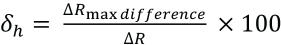
The measurement of abdominal circumference elongation during breathing is a typical example of the application of strain sensing in smart textiles.21,104,105 These smart textiles come in the form of belly belts, chest straps,106,107 fitted shirts, or vests. 108 The bands are placed around the rib cage under the armpits and around the abdomen at the level of the umbilicus (belly button). The embedded strain sensors are connected to electronic processing systems (the processing box) to obtain digital waveforms as shown in Fig. 4.
(a) Prototype breathing chest band with signal acquisition, processing and transmission attachments for measuring respiration rate of a user and (b) chest band being used to measure breathing of a user riding a stationary bike.
During respiration, the cross-sectional area of the rib cage and abdomen increases, altering the resistance of the sensor and the frequency of oscillation. The increase in cross-sectional area is computed to be proportional to lung volumes. The electronics convert this change in frequency to a digital respiration waveform, where the amplitude of the waveform is proportional to the respired breath volume. Studies of other body part movement, such as the wrist, have been reported. 109 There are also reports of non-wearable/contactless breathing sensors, where the sensors have been embedded in chairs 110 and in beds. 111 These physiological applications, though still in an elementary stage, have the potential for long-term monitoring of cardio and lung related convalescents outside of the hospital environment.
Gait Analysis, Physical Activity Tracking, and Motor Rehabilitation Analysis
Gait analysis describes the systematic study of human locomotion. This type of analysis encompasses the measurement, description, and assessment of quantities that characterize human movement. A standard gait analysis method is based on a multi-camera motion capture system and force platform with the capability of measuring ground-reaction forces. This has been successfully developed and applied in a number of gait laboratories. 112 The application of smart textiles as an alternative gait analysis method is not only comparatively inexpensive, but also permits environment studies outside the laboratory.
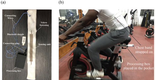
Physical activity tracking helps one to assess activities against set targets. It can, therefore, be a great way to stay motivated and meet one's physical activity goals. In some types of sports training, the method can recognize shortcomings in athletic performance, and based on that assessment, appropriate tactics can be designed. Fig. 5a shows a strain sensor embedded in a pair of gloves for tracking the motion of the fingers during a piano performance. 113 Data obtained from the performances of amateur and professional performers can help in designing tutorials for learners and also help professionals evaluate their performances. Monitoring joint angles through wearable systems enables human posture and gesture to be reconstructed as a support for physical rehabilitation both in clinics and outside the hospital or clinic environment. Strain sensors can also be embedded in arm and knee braces, knee sleeves, and tight fitting pants of athletes to track physical activity and movement. 114
(a) Strain sensor embedded in a pair of gloves to detect motion of the fingers. Image reprinted with permission. 113 Copyright 2016, American Chemical Society. (b) Knitted strain sensor fixed to a knee sleeve prototype for application in personal training and rehabilitation following injury. Image reprinted with permission. 92 Copyright 2015, American Chemical Society.
Examples of prototypes for these applications include wearable goniometers, 115 physical activity trackers, 114 human posture and gesture monitoring, 116 prototypes for measuring human trunk movement, 117 and sensors for measuring movement in wearable telemonitoring applications. 118 Fig. 5b shows the process of fabricating a strain sensor using PU/PEDOT:PSS (polyurethane/poly(3,4-ethylenedio xythiophene):poly(styrenesulfonate)) fibers, subsequently knitted with a spandex yarn for application in personal training and rehabilitation following injury. 119
Prosthetics and Robotic Control
Robotics involves the design, construction, operation, and use of robots, as well as computer systems for their control, sensory feedback, and information processing. These technologies are used to fabricate machines capable of substituting for, or replicating, human actions. 120 A robot or a robotic system must be comprised of a movable mechanism, influenced by sensing, planning, actuation, and control components. 121 In Fig. 6, a weft-knitted strain sensor embedded in a robotic finger to transmit touch sensing data to the main controller via a controller area network (CAN) bus system is shown. 122 Tactile sensing and locomotion are the two main forms of robotic control that have found application in smart textiles. Human tactile sensing has generally served as a reference point for tactile sensing in robotics. 123
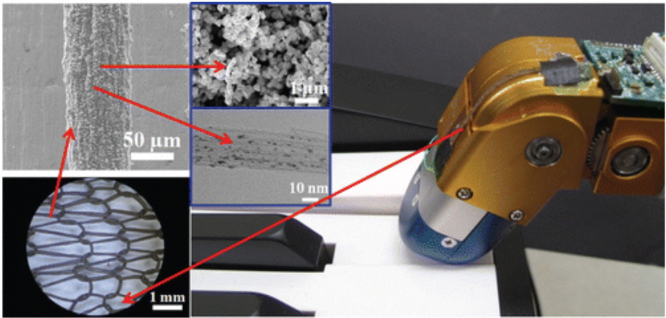
Weft-knitted strain sensor embedded in a robotic finger for control. Image reprinted with permission. 121 Copyright 2014, American Chemical Society.
The complexity of sensing in robotics cannot be compared with the human system. 123 Robotic tactile sensing is mainly based on detection and measurement of forces in a predetermined area only. Tangential traction is one means effecting robotic tactile sensing in smart textiles. 124 Traction, or tractive force, is the force used to generate motion between a body and a tangential surface through the use of dry friction, although the use of shear force on the surface is also commonly used.
Pile-knitted fabrics embedded with conductive sensitive yarns are designed to detect tangential traction. Ho et al. report a knitted robotic skin with a pile-shaped surface having the ability to detect tangential traction and sensing of a normal load. 123
Other applications, such as artificial muscles, have been cited. 125 These artificial muscles are directed towards improvement in the manufacture of prosthetic hands and limbs. Such prosthetics are usually fabricated with electric motors or pneumatic systems. These provide fast responses and have high power densities, but are bulky, heavy, stiff, noisy, non-biological in feeling, and as such, less accepted by the end user. Conversely, the textile alternatives are considered to be lightweight, soft, and lifelike, and move as smoothly and silently as their biological counterparts.
Conclusion
This review presented work on recent trends in the design, development, and manufacture of soft strain sensors for smart and intelligent textile applications. This type of sensor serves to alleviate current drawbacks in smart apparel production, where the smart components are not textilelike, tend to be rigid, and extrinsic to the textile materials. The preferred sensing capabilities should be inherent to the apparel and provide wearer comfort during long term use among other benefits.
Inherent sensor integration using sensitive conductive fibers/yarns has been largely successful. Strain sensors can be produced by knitting together a sensitive (conductive) yarn and a non-sensitive (nonconductive) yarn in the fabric structure. Various types of sensitive yarns and fabric structures are knittable on state of the art knitting machines with advanced design software capabilities.
However, for the potential of inherent smart functionality embedment to be fully harnessed, the following important outstanding issues need to be resolved. In terms of sensitive yarn development, there is the need for developing yarns with high conductivity, good flexibility, and at suitable yarn counts. Good wet processing and laundry performance capabilities are also required of these yarns. Fabric structure deformation and subsequent deformation signal extraction is one area that needs further developing. Advanced computation and modeling tools are needed to clearly reflect loop and yarn configurations in response to stress.
Currently, there are no standardized systems for evaluating textile strain sensors, limiting a clear basis for results comparisons between researches. Research is also lacking in the development of portable signal processing systems to connect and extract sensitive deformation information. Piezoresistive signals extracted in their raw forms tend to be non-linear and therefore signal processing systems are required to process and filter the signals for usable applications. The future of sensor enhanced smart garments lies in the development of fiber-based soft strain sensor technology, which is directly linked to the need for sensitive fiber and yarn development and efficient fabric structure deformation signal extraction.