
Abstract
This study presents textile based resistive pressure sensor that incorporates off-the-shelf PES/stainless steel conductive yarn and nonconductive acrylic yarn. The fabrication process involves integrating the resistive pressure sensors directly into the base fabric during one knitting operation through computerized machine knitting technology with little human involvement. This work also explores opportunities for manufacturing of soft, highly flexible, and easily controllable double-layered out-of-plane sensors in an easily scalable way. A custom resistance measuring circuit was built to characterize the sensors and the resulting equivalent resistance under various loads, i.e., (0 g–900 g). Reproducibility was confirmed by developing and testing several sensors with the same structural characteristics. The results obtained from the experiments showed that the conductive yarn types and the design parameters significantly affect the sensing properties of knitted sensors. It has been found that sensor types 2, 5, and 6 show better stability, repeatability, high response and recovery time, dynamic ranges, and sensitivity when subjected to various loadings, compared to other developed sensors in this work. As a proof of concept, this sensor demonstrates various smart textile applications, including interactive sleeves for wearable user interface, soft controllable switch, and human movement detection.
Keywords
Introduction
Textiles have been used as conformable coverings next to skin for thousands of years in the context of social and protective functions. Nowadays textiles are found in daily human life due to their wide range of applications, spanning apparels, home furnishings, furniture, vehicles, plush toys, airplanes, etc. Because of many of these advantages textiles demonstrate, the field of wearable electronics has recently begun to use textiles as materials of choice. This attribute of versatility also accelerates the world toward the vision of ubiquitous computing. 1 In this concern, many researchers and professionals developed highly flexible and palpable smart textiles to overcome the boundary between hard electronics and standard soft form.2,3 Smart textiles based on fabric sensors to monitor heart rate,4–6 respiration,7–9 gesture, 10 and posture 11 have been explored in many applications.
In the context of smart textiles, pressure sensors based on textile-based structures are currently a key developing field. Generally, the purpose of pressure sensor is to transform various mechanical stimuli into electrical output. Variations in electrical signals such as resistance 12 and capacitance13–15 can be recognized by pressure sensors. Textile-based wearable sensors enable the measurement of physiological signals exerted by body parts where comfortability and sensing reliability are required. Unlike attachable rigid sensors, textile-based sensors are built directly into textile constructions.8,12,16–18
Usually, resistive pressure sensing interfaces are composed of mainly two conductive fabrics separated by a semi-conductive or resistive sheet.11,19,20 A considerable amount of research work has been explored on the fabrication of textile-based resistive pressure sensors through embroidery,21–23 knitting,12,24–28 weaving, 29 and printing. 14 Most wearable sensors are often made using the sandwich method, which involves joining two or more layers of conductive fabric together while incorporating the functional substances in between.19,30,31 Researchers have also developed eCushion 11 for analyzing sitting posture, Flextiles 32 to detect pressure on prosthetic limbs, and Smart-Mat 20 to count and recognize various types of exercises. Unlike these multilayer resistive sensing approaches, some research work33,34 shows resistive sensing properties at the yarn level.
Generally, embroidery is considered one of the early-stage fabric embellishment techniques to develop smart textiles, but now researchers have focused on flat bed knitting technology due to its distinct feature. The machine knitting technology now provides the capability of architecting any sensing interface arbitrarily. 12 This digital machine knitting also enables the user to fabricate easily compared to weaving, which requires pre-processing. In the context of wearer comfortability, most of the time embroidered fabric is less comfortable as it requires fabric backing, whereas machine knitted fabric has no such drawback.
In this article, resistive pressure sensors were made with a computerized flatbed knitting machine. These sensors were fabricated with PES/stainless steel conductive yarn using short courses knitting technique. Thanks to the computerized machine knitting method, which makes it simple to incorporate these sensors into other nonconductive textiles during a single knitting process. Finally, various sets of applications of the developed resistive pressure sensor were demonstrated, including an interactive sleeve embedded with knitted resistive sensor, human movement detector, and highly flexible and easily controllable soft switch.
Materials and methods
Materials
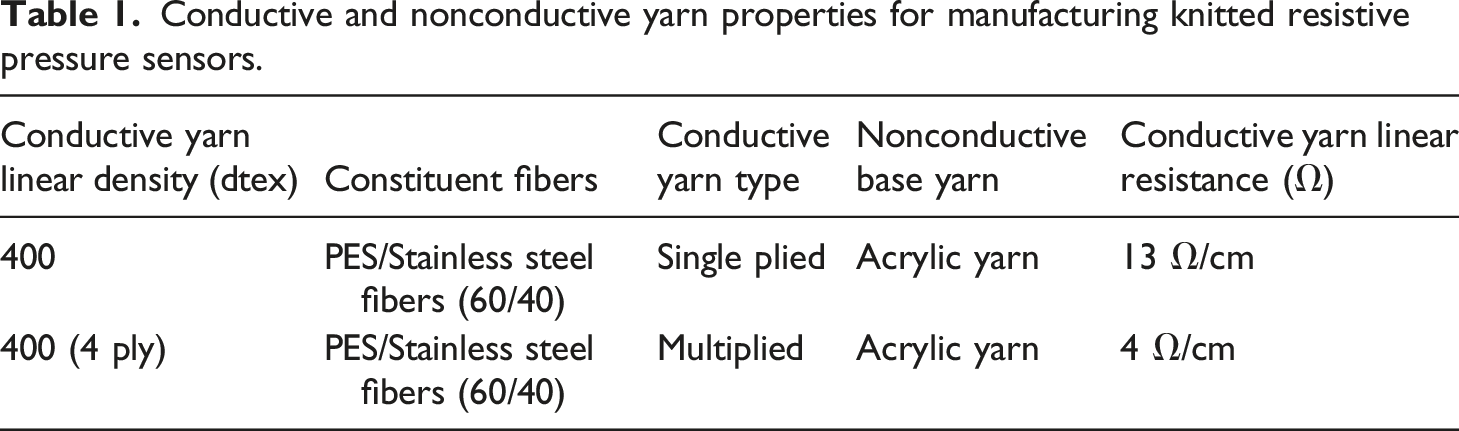
Conductive and nonconductive yarn properties for manufacturing knitted resistive pressure sensors.
Knitting program
The KnitPaint module of Shima Seiki SDS One Apex-3 software was used to give the programming instructions to the SSR 112_14G computerized knitting machine. The machine comes with this unique design software. However, it is not applicable to all knitting machines from other manufacturers. The programming instructions are provided in this software using various colors. Each of the colors stands for a code that can be specified later on the machine.
Figure 1 shows knitting program for the desired sensor, which is mainly divided into three parts. The middle portion is the fabric design, and the left and right vertical lines are called option lines, which are used to give different commands to the machine, including yarn carrier selection, machine speed, loop length variation, takedown speed, etc. Knitting Program of the desired knitted sensor on KnitPaint module of SDS One Apex-3 software.
Fabrication of knitted resistive sensor
The fabrication of resistive pressure sensor using the Shima Seiki SSR 112_14G knitting machine is shown in Figure 2. The prototype was single jersey knitted except for the sensing area, which used short courses knitting technique to create a double-layered out-of-plane sensing fabric. This knitting technique utilized both the front and back needle beds of the flat bed knitting machine. Two yarn carriers were used to fabricate the desired sensor. One carrier was responsible for creating a single jersey base structure, and the second carrier was used for integrating conductive yarn into the base fabric. The carriage performs knitting on the front bed, while the loops on the rear bed were retained without clearing by the needles upon achieving the required sensor dimension. Once the required dimension was achieved, the loops were transferred from the rear bed to the front bed. Then nonconductive fibers are manually infused in between the upper and lower layers to make the sensor more stable in ohmic sensing and enable it to get back to its initial state with negligible resistance drop for long term applications. The machine parameters were adjusted on the basis of knit structure, and the carriage speed was 0.35 m/s. For the sensor fabrication process, two types of conductive yarn, such as one of 400 dtex and another of 400 dtex 4 ply, were employed. In both cases, 190 dtex-2 ply acrylic yarn was used as the non-conductive base yarn. For each kind of conductive yarn, the number of conductive short courses varied in the fabricated sensors. As a result, six different types of sensors were created, as shown in Table 2, where the number of wales was seven and non-conductive acrylic yarns were used as the base for all sensor types. Fabrication of knitted resistive pressure sensor. (a) Digital knitting program on KnitPaint module of SDS One Apex-3 software, (b) Knitting with conductive yarn with appropriate machine settings, (c) Needle bed view during knitting (grey yarn is conductive and red yarn is acrylic base yarn) and, (d) Knitted resistive pressure sensing fabric. Fabricated sensor types.

Sensing principle of the developed sensor
Embedding conductive yarns at specific positions on the top and bottom layers independently allows for the sensing capability shown in Figure 3. The height of the sensing interface can be easily fine-tuned by simply increasing the number of conductive short courses, as shown in Figure 3(b). During the resting state, when no external load is applied, only a small number of electrical contacts exist in the top conductive layer. When any external load is applied, the top conductive layer comes into contact with the bottom conductive layer, resulting in a decrease in resistance due to the formation of more electrical contacts. The resistive pressure sensing structure. (a) The double-layered interface fabricated with conductive yarn (Yellow) and nonconductive acrylic yarn (Red) and, (b) the cross-sectional view of the sensing structure.
Resistance measuring circuit
An Arduino Uno (ATmega328) microcontroller was used to create a circuit to measure the resistance changes caused by different loadings as shown in Figure 4. Voltage divider rule was used using microcontroller to measure the resistance under touch pressure. The precise loading applied by the finger was measured using a force-sensitive resistor (FSR). When a finger was pressed on the sensor, the FSR, which was positioned beneath the sensor, simultaneously read the loadings and sent the information to the microcontroller. Resistance measurement. (a) Arduino Uno based resistance measuring circuit architecture and, (b) Connecting the machine knitted sensor to an Arduino using Alligator clips.
Sensor characterization
The fabricated sensors were characterized by connecting them to the customized resistance measuring circuit via alligator clips, as shown in Figure 4. Then load was applied to the sensor in two ways, i.e., static loading by placing the dead weight on top of the sensor and continuous loading through the finger. To evaluate the fabricated sensors’ performances under various loadings, each test was performed five times for each sensor.
Results and discussion
Dynamic ranges of the developed sensor
In this section, to examine the sensing behaviors of the fabricated sensors, experiments on evaluating the resistance value at resting and pressing states were conducted. The total of six fabricated sensors as listed in Table 2 can be classified into two groups based on the conductive yarn type, i.e., single and multiplied. For each group, three types of sensors were constructed by integrating 1, 3, and 5 conductive short courses. In particular, the resistance difference between zero-load and maximum load for each of the sensors was examined, which is characterized as a measure of dynamic range.
21
The results are presented in Figure 5. Overall, higher dynamic ranges were observed for sensor types 1 and 4, but they showed unstable electrical interactions as only a few amounts of conductive yarn were gathered in the sensing unit, resulting in less loop-through-loop electrical contact. Although this causes higher resistance on these sensors in resting state, they exhibit less resiliency after several test cycles. On the other end, since more conductive short courses were embedded in the top layer (Figure 3) of sensor types 3 and 6, they showed lower resistance at zero load compared to sensor types 1 and 4. This is due to the accumulation of more conductive short courses, which enables more electrical loop-through-loop contact. The gathered conductive short courses interact with each other in the resting state, resulting in a decrease in resistance. In the case of sensor types 2 and 5, three conductive short courses are gathered in the sensing unit, which makes the structures more balanced in the resting state. Multiple test cycles revealed that sensor types 2 and 5 exhibited stable dynamic ranges due to their good resiliency, i.e., returning to their original state. Dynamic ranges of the sensor fabricated using (a) single plied and (b) multiplied conductive yarns.
Sensor performance under loadings
For the characterization of the sensor’s performance, connecting wires were connected to the sensor to measure the maximum resistance changes when deformation occurred. Applying an external load would cause deformation of the upper conductive layer, which would touch the lower conductive layer. With small loadings, the stitch contact points of the upper conductive layer were initially increased and then intermeshed with the lower layer, resulting in more conductive connections, which led to a decrease in resistance. Figures 6 and 7 show the resistance-load curves for all sensors. These figures demonstrate that as the applied load increases, the resistance decreases, indicating good ohmic characteristics. It was observed that type 2 and type 5 sensors exhibited consistent readings throughout the applied pressure range of 0 to 900 g, although the resistance was constant after 900 g loads. The sensor type 6 showed constant resistance after 900 g loads while type 1, type 3, and type 4 sensors always give random resistance drops as represented in Figure 7. For almost linear resistance drop, type 2, type 5, and type 6 can be used as knitted sensors in the range 0 to 900 g loads in working resistance ranges of 5000 Ω to 400 Ω, 7000 Ω to 400 Ω, and 5500 Ω to 400 Ω respectively. The Resistance – Load graph of the sensors fabricated using single-plied yarn. The Resistance – Load graph of the sensors fabricated using multiplied yarn.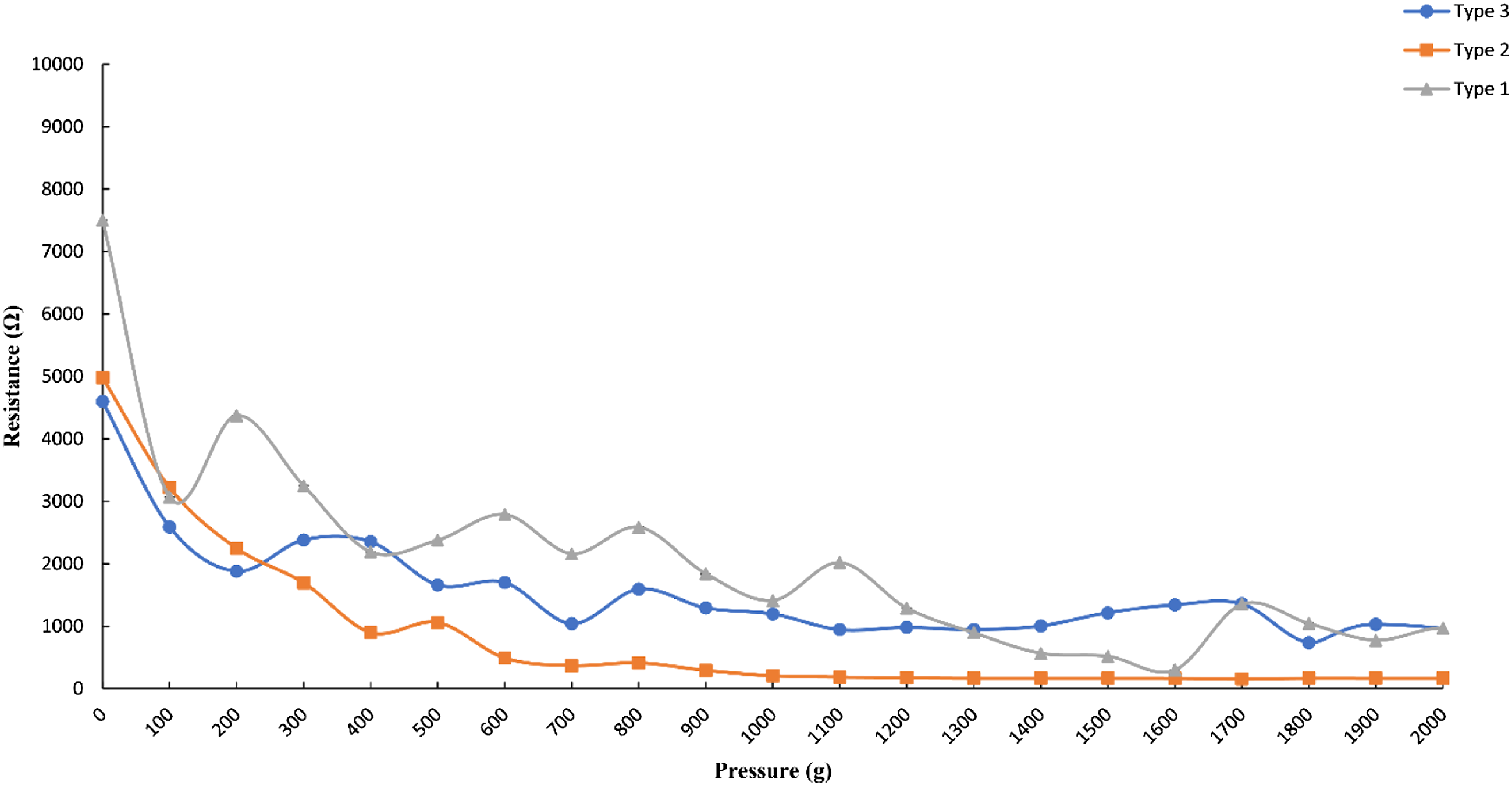

Response and recovery time of the sensors
Figure 8(a)–(c) demonstrates single cycle response, stabilizing, and recovery time for sensor types 2, 5, and 6. Initially, the peak resistances were 4200 Ω, 7000 Ω, and 10,000 Ω for these sensors respectively. As soon as load was applied, the resistance decreased according to the amplitude of the applied load.
35
For sensor types 5 and 6, the response, stabilizing, and recovery time were determined to be ∼ 100 ms, ∼300 ms, and ∼100 ms, whereas these values for sensor type 2 were ∼200 ms, ∼300 ms, and ∼200 ms. It is clearly seen that these sensors exhibit good response and recovery speed, enabling them to perform as flexible sensors for smart wearable applications. Performance characteristics of resistive pressure sensor type 2, 5, and 6. (a)–(c) Response and recovery for a loading/unloading cycle indicates good response, stabilizing, and recovery time for these sensor types respectively. (d)–(f) Cyclic test result for these sensors. The results indicate excellent repetitiveness of sensor type 2, 5, and 6 respectively.
Repetitiveness
To test the durability and repetitiveness of the sensors, i.e., sensor types 2, 5, and 6, a 400-cycle cyclic test was accomplished by successive pressings on the sensors.13,36 As shown in Figure 8(d)–(f), during cyclic loading and unloading, each of the sensors demonstrated good repeatability, and the dynamic ranges of the resistance values of these sensors were not significantly changed after the test. This is because sensor types 2, 5, and 6 have the most stable structure due to a balance of sensor size and number of conductive courses, which enabled these sensors to come back to their original shape after each cycle.
Sensitivity and long-term stability of the sensors
Figure 9 shows the sensitivity curve and long-term stability attributes of the developed resistive pressure sensors, i.e., sensor types 2, 5, and 6. Here, the pressure sensitivity of these sensors was enumerated by using the formula S= (∆R/R0)/P, where P indicates the applied pressure, ∆R denotes the change in resistance, and R0 is the initial resistance at zero pressure.36–39 Sensitivity and stability attributes of sensor type 2, 5, and 6. (a)–(c) Sensitivity curves for these sensors respectively. The sensitivity of these sensors are 1.0 kPa−1, 1.1 kPa−1, and 1.1 kPa−1 across the pressure range of 0 kPa and 88 kPa. (d)–(f) Long term stability test result for these sensors respectively exhibit relative change in resistance (Ω) with increasing load of 200 gm.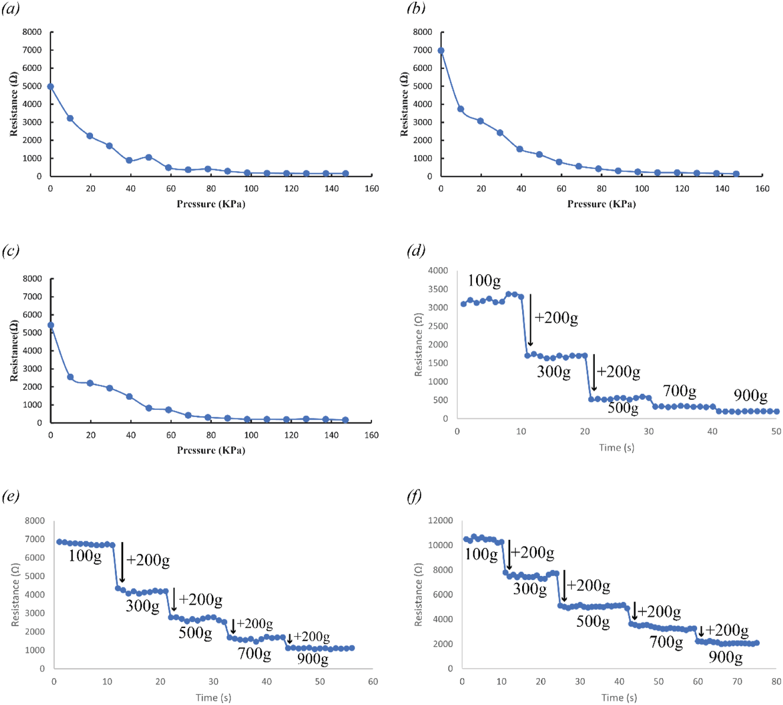
The sensitivity of the sensor types 2, 5, and 6 were determined to be 1.0 kPa−1, 1.1 kPa−1, and 1.1 kPa−1 respectively. These sensors exhibit almost linear response over a broad range of pressure between 0 kPa and 88 kPa as shown in Figure 9(a)–(c). As the sensitivity of knitted sensing fabric depends on the stitch contact resistance, these double-layered out-of-plane sensors offer good stitch contact while resting and pressing, resulting in optimum sensitivity. Sensitivity also depends on the conductive surface area as well as the resistance of the conductive yarn. 35 So, by increasing the sensing area of these sensors and incorporating conductive yarn with a high resistance value, the sensitivity of these sensors can easily be fine-tuned.
The sensitivity of the sensors fabricated in this work is nearly comparable to existing contemporary resistive pressure sensors.40–42 Some of the previously reported sensors showed remarkable sensitivity while their applicable pressure range was lower, and they showed nonlinear response.43–45 Recently, some researchers also developed and proposed multi-layered tactile sensors,46,47 which demonstrate high sensitivity, i.e., 26.13 kPa−1 and 47.7 kPa−1 across a broad pressure range. To examine the stability of these sensors, a long-term stability test was further accomplished. 36 Our developed sensors exhibited good stability, while the applied load, i.e., 200 g was stable at different times, as depicted in Figure 9(d)–(f).
Wash durability of the sensors
The machine knitted resistive pressure sensors were washed according to the standard test protocol ISO 105-C01 to examine their performance after several washing cycles.
35
As machine knitted sensors consist of loops, the primary concern after washing is to check for loop damages and degradation in their sensing performances. The sample was allowed to undergo mechanical agitation in a mechanical laundering device. A commercially available washing powder was used for the test. After ten washing cycles, sensors were visually examined and found no broken loops. And the sensing performances were evaluated by accomplishing a loading/unloading cycle between 0 g (resting state) and 900 g (pressing state) loads. Figure 10 shows that after few washes, resistance increases a little for sensor types 2, 5, and 6 in both states, i.e., the resting and pressing states. This might occur due to the mechanical agitation during washing, which may cause partial disturbance of the loop-through-loop contact points in the out-of-plane structure, and after that, resistance becomes stable. The obtained dynamic ranges of resistance values assured that each sensor behaved similarly after washing, as Bekaert (conductive yarn supplier) claims. Dynamic ranges of sensor (a) type 2, (b) type 5, and (c) type 6 after several washing cycles.
Comparative study
Comparison of different textile-based sensors.

Applications
The developed sensor can be implemented from a wide range of perspectives. Here various sets of applications of the developed resistive pressure sensor are demonstrated, including an interactive sleeve integrated with knitted resistive sensors, human movement detector, and highly flexible and easily controllable soft switch.
Interactive sleeve integrated with knitted resistive sensor
The developed sensor can be easily embedded into a sleeve, as shown in Figure 11 to allow patients to alert medical personnel when necessary or serve as an accessible interface for the wearer. This might be used as a human-machine interface to control devices like smartphones, music players (Supplementary video S1), and alarm clocks. On-body integration of knitted resistive pressure sensor. (a) Sleeve with embedded resistive pressure sensor and, (b) Pressing one of the pressure sensors.
Human movement detection
The developed sensing interface can act as a human movement detector. To investigate the finger pressure sensing performance of the developed sensor in terms of real-life implications, the sensor type 5 was connected to the controller. Figure 12 exhibits the resistance-time graphs where resistance dropped during the finger was pressed. It was seen that the sensor has good resiliency, making it capable of acting as a wearable sensor for human movement detection. Application of resistive pressure sensor for finger pressure detection. Resistance-Time graph shows the resistance change when the finger continues to press.
Highly flexible and easily controllable soft switch
Figure 13 shows the suitability of the developed sensor to use as a controllable soft switch where changes in resistance were programmed into three slots, assigning individually colored LEDs to blink as shown in Supplementary Video S2. Application of developed resistive sensor as a soft switch. Successive increasing of pressure onto the developed sensor to blink (a) one LED, (b) two LEDs and, (c) three LEDs.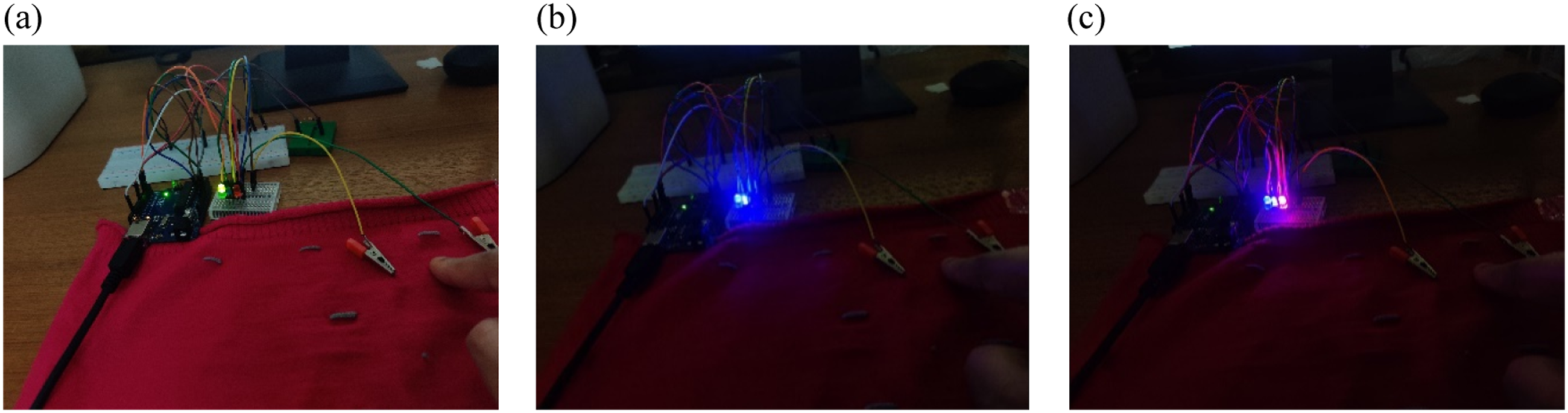
Conclusion
In this paper, double-layered out-of-plane knitted pressure sensors based on resistive sensing principle and their possible applications are introduced. These resistive pressure sensors, unique to computerized flatbed knitting machine, have been realized by using PES/stainless steel conductive yarn and nonconductive acrylic yarn. Electromechanical characterizations were conducted to examine the effects of various structural parameters, i.e., number of conductive short courses and linear density of functional yarns, on the sensing properties of various sensor types. It has been revealed that sensor types 2, 5, and 6 show better sensing performance when subjected to different loadings, compared to other types of sensors fabricated in this work. These sensors demonstrate broad dynamic ranges and good cyclic stability (400 cycles) with negligible drift of resistance. They also exhibit better wash durability (>10 washes), sensitivity (1-1.1 kPa−1) with a broad range of pressure between 0 kPa and 88 kPa, fast response and recovery time, which are suitable for various wearable applications. Several example demonstrations of the developed sensors, including interactive sleeves for wearable user interface, soft controllable switch, and human movement detection, have been shown.
Supplemental Material
Supplemental Material
Footnotes
Acknowledgments
The research has been done at the Smart and Functional Textiles Lab, Department of Fabric Engineering, Bangladesh University of Textiles (BUTEX). All authors acknowledge the authorities of Bangladesh University of Textiles for giving the opportunity to complete this research.
Declaration of Conflicting Interests
The author(s) declared no potential conflicts of interest with respect to the research, authorship, and/or publication of this article.
Funding
The author(s) received no financial support for the research, authorship, and/or publication of this article.
Supplemental Material
Supplemental material for this article is available online.
References
Supplementary Material
Please find the following supplemental material available below.
For Open Access articles published under a Creative Commons License, all supplemental material carries the same license as the article it is associated with.
For non-Open Access articles published, all supplemental material carries a non-exclusive license, and permission requests for re-use of supplemental material or any part of supplemental material shall be sent directly to the copyright owner as specified in the copyright notice associated with the article.