
Abstract
It is hypothesized that two cotton fabrics treated with dissimilarly doped nanocellulose will display a thermal electric effect, similar to the “Peltier effect,” when a direct current is applied. Middleweight plain weave cotton fabric samples were pretreated by scouring, drying, and then dip-coated in a solution mixture of doping material and nanofibrillated cellulose. Two samples were prepared with silver nanowires and polypyrrole conductive polymer as conductive doping materials, respectively, and one sample only with nanofibrillated cellulose. Coated fabrics were dried and electrically characterized. Samples were paired and cross-tested. Temperature gradients and electrical currents were measured across conductive sample pairs, and the Peltier effect was demonstrated. The temperature range of the Peltier effect was limited by the Joule heat saturation of fabric.
Introduction
Cotton is arguably the most versatile and widely-used natural cellulosic polymer. Cotton is durable, soft, comfortable, and is environmentally friendly; however, its use is often limited by its thermal characteristics. New fabric technologies attempt to alter thermal properties through portable heating or cooling systems. These systems often use circulating liquids through tubes to move heat away from the body, and require bulky conditioning modules that are external to the garment. 1 This study proposes creation of a novel cotton fabric with electrically-alterable thermal properties. This would eventually allow the creation of lightweight, comfortable apparel that could alter temperature to suit the wearer. One step in achieving this goal is to create fabrics that demonstrate the thermoelectric property known as the Peltier effect.
In 1834, French physicist Jean Charles Peltier discovered that when an electrical current is made to flow between two dissimilar conductors, heating or cooling will take place at the junction of the conductors, and/or semiconductors. Of the two dissimilar conductors one must be a charge carrier or p-type, and the other must be a charge provider or n-type. When a current is applied across a p-n junction, hole current flows from the lower potential n-type material to the higher potential p-type material (Fig. 1). 1 In the process, heat is absorbed on one side of the junction and released on the other side of the junction, providing a heating and cooling effect. Joule (Ohmic) heat can be generated when electric current flows through a conductor, and it is related to the current and resistance. During this process, Joule (Ohmic) heat is produced due the resistance of the p-type material. Essentially, there are two heat flows created in this process.1,2 The Joule heat component is detrimental to the Peltier effect and limits the differential temperature range between the two conductors.1,3 The Joule heat must be accounted for when determining the true Peltier temperature range.
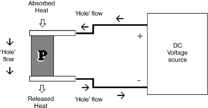
Peltier effect mechanical model. 1
In this study, we will evaluate nanosilver wires, a metal, as an n-type conductor, and polypyrrole, a polymer, as the p-type semiconductor. Since both of these materials exhibit structural integrity flaws,1,4 we will combine them with nanofibrillated cellulose to form a nanocomposite fabric coating. Cotton fabric samples will be coated with the nano-composite using the “dip and dry” method. 4
Nanocellulose is a material known for its ability to bond natural fibers and increase structural integrity. Depositing nanocellulose onto natural fibers to create hierarchical fiber-reinforced nanocomposites is described in existing literature. 5 The application of nanocellulose in composite materials has increased recently due to its ability to increase stiffness and strength while remaining lightweight.6,7 As a renewable, sustainable, and biodegradable resource, nano-cellulose is environmentally friendly. Common forms of nanocellulose are crystalline and fibrillated. 5 The nanocellulose used in this study is nanofibrillated cellulose (NFC) derived from bleached kraft pulp, a waste product of the lumber and paper industries.
The primary goal of this research is to create a conductive cotton fabric, coat it with conductive nanocomposites then, use it to demonstrate the Peltier thermoelectric principle. We wish to add to the existing body of knowledge regarding smart textiles and electrically-alterable fabrics.
Experimental
Materials
Fabric of 100% cotton was chosen for this experiment. Fabric was bleached, balanced (with same ends per inch for filling and warp yarns), and with a plain weave weighing 4 oz/yd2 (135.6 g/m2). Fabric was cut into 25 samples of 1 × 2 in. The fabric samples were scoured in an aqueous solution of 5% Na2CO3 at 95 °C for a period of 30 min with agitation. The purpose of the scouring was to remove any impurities that were introduced to the fabric during storage. Tree, 5-min rinses in 95 °C deionized water were conducted following the scouring. The samples were divided into groups of five, then oven dried at 100 °C for a period of 24 h to reduce the moisture content of the samples (Table I) in preparation for dip coating. 4
Sample Weights (g) During H2O Reduction at 100 °C for 24 h
Silver nanowires (nAg, 35 nm × 10 μm) were purchased from Bluenano Advanced Nanomaterials Manufacturing 8 (SLV-NW-35) as a dispersion in ethanol. Elemental analysis gave Ag (99.5%+), C (0.03%), H (0.23%), and O (0.14%). The silver nanowires provided available electrons for transport of electrical current.
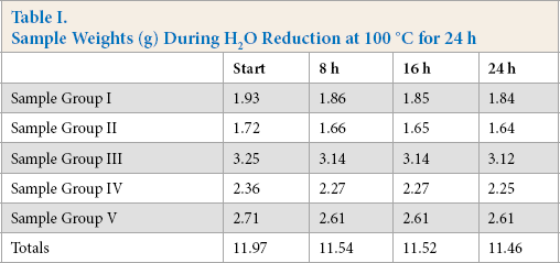
Polypyrrole (PPy) (Fig. 2), p-doped with organic sulfonic acid, and with a conductivity of 30 S/cm was purchased from Sigma-Aldrich (530573). 9 This material was in solid form with a 20 wt% loading of polypyrrole in carbon black. The p-type dopant caused the PPy to be positively charged, creating an abundance of holes through which electron current may flow.
General chemical structure of polypyrrole.
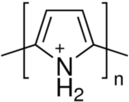
Nanofibrillated cellulose hydrogel (2% v/v NFC), was obtained from the Pilot Scale Textile Chemistry Lab at the University of Georgia, Athens. NFC hydrogel was prepared with waste cellulose kraft pulp using a Gaulin homogenizer. The images from transmission electron microscopy (TEM) and atomic force microscopy (AFM) in Fig. 3 show isolated nano-size cellulose fibers, whose width and length range from 10 to 50 nm and up to several micrometers, respectively.
Nanofibrillated cellulose from 2% hydrogel: (A) TEM (scale bar 200 nm) and (B) AFM images of NFC fibers.
Laboratory Equipment
Power was provided by an Extech Instruments DC regulated power supply, model 382202 capable of providing up to 18 V at 3 A with load regulation less than 0.2%. The power supply was operated in constant current mode for this experiment.
A GW digital multi-meter, model GDM-8055, was used for measurements of current, voltage, and resistance. The meter featured a 4-wire sensing feature for the accurate measurement of resistance.
Temperatures were recorded using two electronic thermometers; an Omega Engineering Model HH506A dual-logging thermometer and a Sper Scientific 800005. Both were equipped with K type temperature probes and could range from -200 °C to 1300 °C.
A Zeiss 1450EP Scanning Electron Microscope (SEM) was used for visual characterization of materials used in this experiment.
Methods
Fabric Coating Preparation
Tree variations of coatings were prepared using NFC and nAg or PPy. Coating 1 consisted of 4 mL of NFC hydro-gel (2%), coating 2 used 2 mL of NFC hydrogel (2%) with 2 mL of nAg solution, and coating 3 contained 4 mL of NFC hydrogel (2%) with 0.137g PPy, which yielded a 97.5% NFC and 2.5% PPy w/w mixture. Each of the coatings was manually stirred for 1 min and shaken on a vortex machine until the composite material appeared evenly distributed.
Fabric Sample Preparation
Cotton fabrics were first scoured, and then placed in an oven at 100 °C for 24 h to reduce sample moisture. The pretreated fabrics were randomly placed into four treatment groups of three samples each, and the remaining fabric samples were placed in a desiccator for future use. The samples in three of the treatment groups were dip coated with the three variants of NFC hydrogel coating, while the fourth group received no treatment, making it the control group. The samples were immersed into respective coating material for 10 min, and then were rolled to remove excess material. After one dip coating, the samples were air dried in a vent hood at 21 °C for 24 h, and stored at room temperature for the remainder of this experiment (Fig. 4).
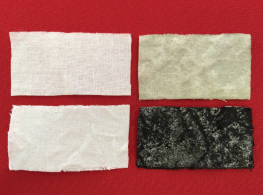
Coated samples, clockwise from top left: control, nAg/NFC, PPy/ NFC, and NFC.
Test Stage Construction
The test stage was constructed inside a SterilGard III biological safety cabinet. The self-contained nature of the cabinet allowed tests to be conducted without large changes in the ambient air temperature that could affect the accuracy of temperature measurements. An asbestos insulating material (6 in. 2 ) was placed in the center of the cabinet. Tree temperature probes were positioned on the stage, two for sample temperature measurement and one for stage temperature measurement (Fig. 5A) The two temperature probes were electrically insulated using non-conductive tape and placed on glass slides. The slides were then anchored to the stage to allow a 1-in. separation of the temperature probes. The third probe was insulated and placed directly on the stage to monitor any residual heat that may affect accurate measurement. Fig. 5B shows the test stage as positioned in the cabinet. The power supply was located external to the cabinet. Power leads were passed into the cabinet underneath the doorsill.
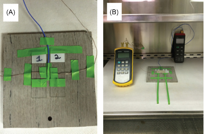
(A) Stage configuration and (B) test stage in cabinet.
Measuring Average Resistance and Conductance
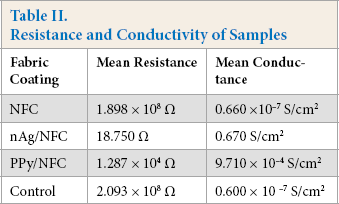
Electrical resistance was measured using four leads, each lead contacting a corner of the fabric. The electrical resistance of each sample was measured three times and was averaged to determine the resistance of the individual sample. The resistances of samples within a treatment group were averaged to determine the resistance of the group. Average resistance was converted to conductance (1/Ω) as seen in Table II. Fabrics with conductive properties were indicated by their comparatively high conductance values.
Resistance and Conductivity of Samples
Sample Morphology
Fabrics from each sample group were studied under the scanning electron microscope (SEM). SEM samples were prepared by carbon sputter coating to prevent electrical charging during examination. Fig. 6A shows the even distribution of NFC across the face of the cotton fabric. Nano-assembly of the NFC occurred across the warp and filling yarns, and had filled in the interstices. Outlines of the yarns can be seen clearly. Fig. 6B indicates a less than even distribution of the PPy/NFC coating across the fabric. Fig. 6C displays the interaction of the NFC and nAg on a cotton fiber. Note that some of the nAg wires were embedded in the cotton fiber and were covered with NFC.
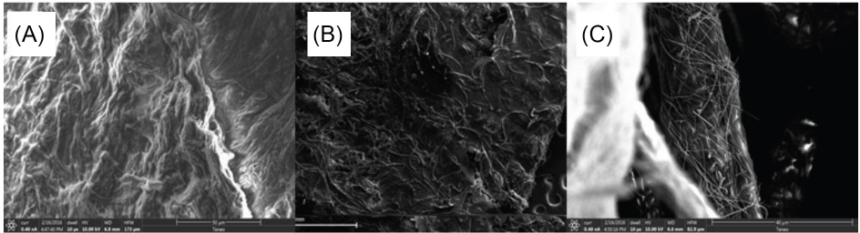
(A) NFC cotton fabric, (B) PPy/NFC cotton fabric, and (C) nAg/NFC cotton fiber.
Joule Heat Characterization
Each sample (three from each group) was placed singly on the test stage and subjected to a range of currents from 300 to 1000 mA. Joule heat temperature readings were taken at test points TP1 and TP2, and recorded for comparison during Peltier effect testing. Samples placed in test position were covered with a glass slide to ensure good contact with the temperature probes. Power supply probes were attached at two opposing corners of the sample and the cabinet door was closed. Current levels from 300 to 1000 mA, in increments of 100 mA, were induced for a period of 5 min each. Stage temperature was monitored during testing and recorded. A period of at least 5 min between test cycles was allowed to prevent heat buildup on the test stage.
Peltier Effect Testing
Testing sample combinations for the Peltier effect requires the creation of two junctions between dissimilar conductors. This was achieved by selecting two similar fabrics from one group and a different fabric from another group. Fig. 7 shows the test placement of two nAg/NFC samples with one PPy/NFC sample. Due to the highly conductive nature of the nAg/NFC samples, they remained in the position shown in Fig. 7, and only the less conductive bridging sample was rotated. As during the Joule heat characterization, current levels from 300 to 1000 mA, in increments of 100 mA, were induced for a period of 5 min each. Stage temperature was monitored during testing and recorded. A period of at least 5 min between test cycles was allowed to prevent heat accumulation. Samples from each group were tested and temperature values were recorded.
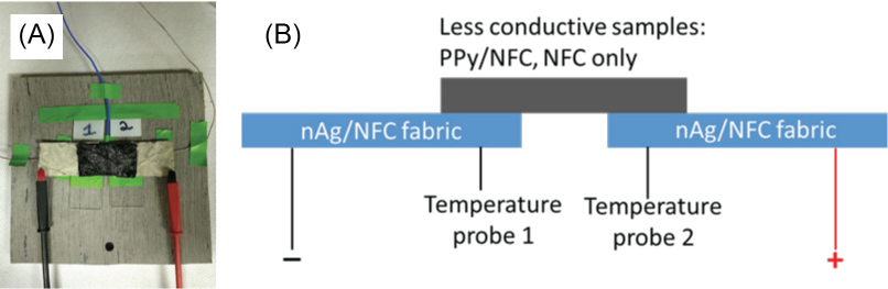
(A) Image and (B) schematics of test stage configuration for Peltier testing.
Results and Discussion
Results from Peltier testing indicate that the Peltier effect existed between nAg/NFC fabrics and PPy/NFC fabrics, but was not observed in any relationship with control or NFC-only fabrics. Fig. 8A illustrates the differential in temperatures of the junctions between nAg/NFC fabric and PPy/NFC fabric, with removal of the Joule heat factor for the fabrics. The graph indicates that a cooling effect occurred as the positive electrical “hole” current flowed from one nAg/NFC fabric to the other, through the PPy/NFC bridge fabric. 1 As noted in the graph (Fig. 8A), there were some anomalies at 600 and 700 mA. This was possibly caused by the unstable interfaces between nAg/NFC and PPy/NFC samples.
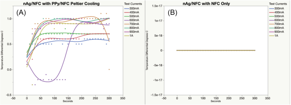
(A) Positive results of Peltier testing and (B) negative indications.
Fig. 8B shows the results of testing nAg/NFC fabric with NFC-only fabric. Since the NFC fabric had such a low conductivity (0.660 × 10⁻⁷ S/cm2), currents that were generated in this experiment caused no change in temperature between junctions. Therefore, no Peltier effect was observed. The control fabric also displayed no Peltier effect.
Conclusion
This exploratory study demonstrated that two cotton fabrics with dissimilar electrical conductivity values generated a cooling and heating (Peltier) effect when electric current was applied. Furthermore, this experiment demonstrated that the use of NFC in a composite fabric coating with conductive metals or polymers enhanced the structural properties, but the influence of NFC on the Peltier effect and the conductive performance of the metals or polymers need further study. Future work will focus on studying the influence of NFC, the dispersion of doping materials in NFC, and their interfacial interactions on the Peltier effect. Other types of p and n type semiconductors with NFC, and the regulation and sustainability of the Peltier effect, will also be investigated. Since mobile power sources offer limited power, increasing the temperature differential at low current levels will be a key factor in adding a Peltier effect cooling feature to smart textiles.
Footnotes
Acknowledgement
We would like to acknowledge 2014-2015 AATCC Foundation Student Research Support for this research study.