
Abstract
This paper presents an extensive review on electrical conductivity in textile fibers and yarns. The focus is an attempt at exhaustively classifying various types of conductive yarns based on their modes of manufacture, composition, and areas of application. Yarn classes include whole metallic yarns, composite conductive yarns, plated yarns, conductive polymer yarns and yarns made of new nano-materials and nano-composites. Electrical conductivity is exploited to effect smart textile applications such as strain sensing, capacitance, antimicrobial activity, antistatic and electromagnetic shielding. The lack of clear distinction in conductive yarn categorization and their possible areas of application are clarified in this review.
Introduction
Electrical conductivity technology was once solely located within the scope of electronic engineering and science applications. However, in the current era, where smart capabilities are being incorporated in virtually all human creations, this technology has been integrated into newer fields, including intelligent textiles. Intelligent and smart textiles are now being produced thanks to the conductive properties found in certain types of fibers and yarns. The distinguishing property of metallic fibers or yarns is in their electrical conductivity.
Conductivity in fibers and yarns are being exploited, not only for conducting electricity and in sensing, but also in delivering antimicrobial,1,2 anti-static,3–5 and electromagnetic shielding (EMS)6–8 properties. Currently, researchers and industry have produced conductive yarns out of whole metals known as metallic yarns, hybrid yarns out of a combination of metallic yarns and conventional textile yarns, yarns laminated with conductive films, yarn coated with conductive solutions, and yarns made from nano-materials.
Although many conductive yarns are suitable for smart textiles, there are no exhaustive classifications of conductive yarns. Some fancy yarns, with minimal metal inclusion for aesthetic effects, are sometimes referred to as conductive yarns. Therefore, this study attempts to classify conductive yarns based on their mode of manufacture, composition, and applications.
The choice of conductive yarns for a smart textile application needs to be considered based on the level of conductivity needed, durability of the conductive component, yarn material content, method to be used in fabrication, wearer suitability, and comfort. Some conductive yarns tend to be heavier than their corresponding normal textile yarns and their brittle characteristics can damage weaving or knitting machinery during production. 9 Apart from possible damage to machinery, this heterogeneity may also cause yarn delamination (for laminated yarns) or possible breakages during production, causing poor signal integrity. They may also be uncomfortable to wear due to abrasion 10 and prone to inducing allergic contact dermatitis.11–13 To alleviate these concerns, the choice of conductive yarns for smart textiles should be made with the above considerations in mind.
Electrical Conductivity
Electrical conduction is the movement of electrically-charged particles through a transmission medium. In physics and electrical engineering, a conductor describes an object or type of material that allows the flow of electrical current in one or more directions. An object made of a conducting material will permit electrical charges to be transferred across the entire surface of the object. 14 If a charge is transferred to the object at a given location, that charge is quickly diffused across the entire surface of the object as the result of electron movement. The outer electrons of conductor atoms are loosely bound and are therefore free to move through the material.
Current is often described as being either direct current (DC) or alternating current (AC) in electrical engineering. 15 When an electric charge is applied, these electron charges will move, repelling each other and allowing the current to flow down the line. This relative movement of electrons within a material is known as electric conductivity. Conductivity is triggered in many ways such as by application of DC or AC current to a conductive material or by simply subjecting a conductive material to stress.
Conductivity is determined by the types of atoms in a material. Materials with high electron mobility (many free electrons) are called conductors, while materials with low electron mobility (few or no free electrons) are called insulators. In insulators, the atoms’ electrons are not easily excited and are stable, preventing or blocking the flow of electricity.
Examples of conductors include silver, copper, gold, aluminum, iron, steel, brass, bronze, mercury, and graphite. Insulators include glass, rubber, oil, asphalt, fiberglass, porcelain, ceramics, quartz, and dry cotton. Some materials are insulators in pure form, but will conduct electricity if they are doped with small quantities of another element or if they contain impurities. For example, most ceramics are excellent insulators, but if doped, a superconductor can be created. The best electrical conductor, under normal temperature and pressure conditions, is metallic silver.
Electrical Resistance, Conductance & Capacitance
The electrical resistance of a conductor is a measure of the difficulty to pass an electric current through that material. The inverse quantity is electrical conductance, the ease with which electrical current passes through that material. The unit of electric resistance is ohm (Ω) and can be computed by dividing the applied voltage by the current. The inverse of resistance is conductance and can also be computed by dividing current by the resistance, the unit being Siemens (S).
Conductance and resistance are useful properties in characterizing conductive materials for smart textile applications. Measurement of electrical resistance is commonly used, instead of conductivity (equivalent to conductance), in determining the electrical properties of materials such as textile yarns and electric wires. Resistance is convenient to measure, straightforward to deduce, and is influenced by the nature of the material, specifically its cross-sectional area and length. It is postulated that if the cross section of any conductor is large, then more electrons can traverse it more easily, amounting to more current flow through the conductor. Also, an increase in the length of the conductor directly increases the path traveled by the electrons. The resistance of a wire is given in Eq. 1.

ρ is resistivity,
Capacitance defines the quality in a material that enables it to store an electrical charge. Capacitors can be found in almost all electronic applications as parts of electrical circuits. Formerly referred to as condensers, capacitors are characterized by a passive two-terminal electrical component used to temporarily store electrical energy in an electric field. There are currently numerous arrays of capacitors for different applications, including supercapacitors 16 for wearable devices. 17
Conductive Fibers and Yarns
The term metallic fiber, in its general sense, simply means a fiber that contains metal. The generic term metallic fiber as adopted by the US Code of Federal Regulations (CFR) is defined as “a manufactured fiber composed of metal, plastic-coated metal, metal-coated plastic, or a core completely covered by metal.” Thus, metallic yarns are those produced from metals, which may be wholly metallic or in colligation with other substances. 18 Because of their conductivity, metallic conductive yarns are usually used for the transportation of current between electrical sources and electronic devices, or to transport the received information from these devices to the processing part in the fabric.
Production and use of metallic yarns and threads can be traced back to the dawn of human civilization. Cultural relics in the forms of armor and royal golden costumes of various civilizations can attest to these assertions. Records of US patents filed and approved between the late 19th century and the beginning of the 20th century show how research into the area was vigorous during those periods. Today, changes in technology have affected the production of whole metallic filaments. There has been a paradigm shift from the manufacture of whole metallic yarns to the production of blended spun yarns (spinning metallic fibers and staple fibers or filaments), 19–21 preparation of conductive composite materials,22–24 coating conventional natural and synthetic fibers and yarns with conductive materials,25,26 novel nano-materials,27,28 and development of new non-metallic inherently conductive materials.29,30 Fig. 1 shows an exhaustive block diagram of conductive yarn classifications.
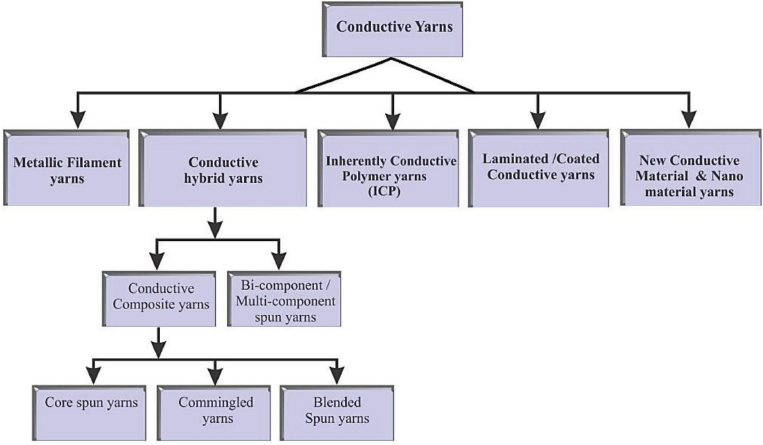
Block diagram of conductive yarn classifications.
Metallic Filaments
Historically, metallic filaments of ∼0.25-mm diameter were fabricated by a continuous heat treatment of metallic wires followed by drawing. The surfaces of metal wires in bundles are coated with separator materials such as metal oxides, graphite, or oils, which prevents the strands from matting during drawing and heat treatments. The wires are inserted into a tube or wrapped with metallic tapes secured at the seams by welding (Fig. 2). They are then subjected to composite wire diameter reduction action by drawing and heating until a desired diameter is attained (Fig. 3). This is followed by subsequent dissolution of the outer tube metal and the coated metal via chemical means to release the produced fine metallic filaments.
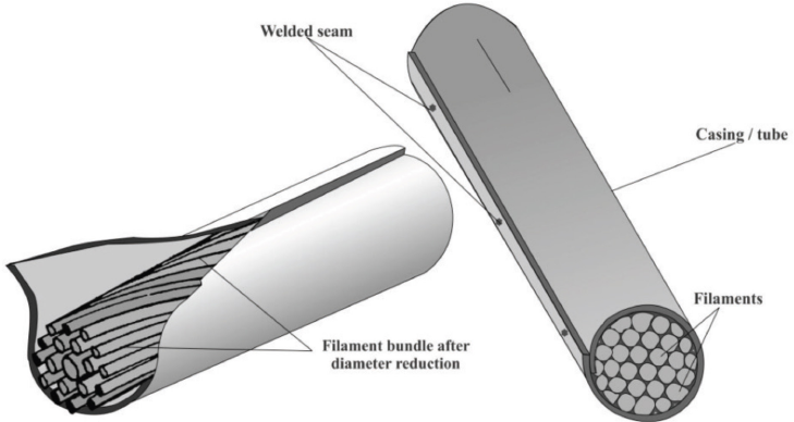
Schematic diagrams of filament bundles in casing.
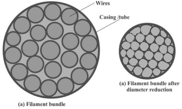
Schematic diagram of cross-sectional view of filament bundles before and after diameter reduction
Underwood, in a clear departure from this technique was granted a patent, (US 1,096,077) for producing metallic yarns from a mass of metallic fibers. 31 Underwood stated “I have discovered that fine metallic fiber cut or shredded from solid metal in the usual manner in which such material is made, or any metallic fiber having rough or serrated edges in contradistinction to smooth wires, may be spun into yarn.” Underwood's process consists of first shredding metal from a solid mass to produce elongated filaments having roughened or serrated surfaces. This is then followed by optional softening of the fibers via annealing and then carding. The metallic roving is then spun into yarn, just like natural conventional staple fibers.
Many patents, however, continue to use wire drawing to produce filaments and to improve on the processes and technique. Takeo and Ogita (US 3,807,026) contributed by developing effective coating materials that enhanced fiber separation after diameter reduction. Other related US patents include 2,050,298; 3,131,469; 3,378,999; 3,394,213; 3,529,343; 3,540,114; 5,890,272; and 6,112,395. 31
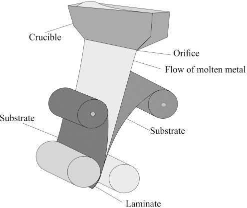
Currently, most industrial production of whole metallic yarns uses Underwood's technique. The process is described such that thin films of metals (e.g., copper, gold, silver and aluminum) are fabricated into ribbons of 30 in. or wider. Fig. 4 presents a schematic description of a metallic ribbon fabrication process in which a jet of extruded molten metal passes onto a cold, moving substrate. The jet fattens into a ribbon and heat is largely lost by conduction into the substrate; the cooling rate is done at high speed. The wide rolls produced are slit into narrow rolls 2 in. to 5 in. wide. These narrow rolls are subsequently slit in bunches across their entire width to micro widths from 1/128 in. (.0078 in.) and wider, and then taken up on plastic spools for shipment to textile mills or led to spindles for yarn spinning. Advances in this technology have paved the way for the commercial production of fine metallic yarns suitable for knitting or weaving into garments.
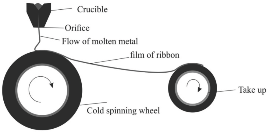
Schematic description of metallic ribbon fabrication process.
Thermal methods, a rapid solidification process-based production of metal fibers and wires by direct extrusion from the hot melt phase, with a subsequent quenching process exist. Making use of the melt-extraction method, refined fiber diameters of ∼50 μm, are melt spun in rotating fluids creating fiber diameters of 50–500 μm. Brittle fibers, especially aluminum and copper, can be made from aluminum and copper alloys using melt extraction. 32
Whole metallic yarns (e.g., made of copper) 33 offer good electrical conductivity in smart fabric circuit networks, when compared to hybrid yarns. However, metallic stainless steel displays lower sensitivity when used as a fabric strain sensor, compared to those made from carbon fibers, due to its small internal friction. 34 Whole metallic yarns are therefore most suitable when functional circuits to transport electric current within textile structures are required. Major drawbacks, however, are harshness or the allergic reactions metallic yarns may trigger when contact is made with the body. In using whole metallic yarn for knitting, base yarns may be used to provide cover.
Hybrid Yarns
Hybrid yarns are yarns formed where materials or fibers of different compositions are spun together into yarn. Hybrid yarns in this study are categorized into composite, bi- and multicomponent yarns. Engineered composite yarns are yarns made with two or more components (i.e., yarns produced via tow-to-tow, filament-to-filament spinning, or combinations thereof).
Conductive Composite Yarns
Recently, conductive composite yarns have been widely used in manufacturing smart and other personal protective clothing because of their properties (e.g., flexibility, thermal expansion matching, and being lightweight). 35 This category includes core spun yarn, commingled yarns, and blended spun yarns.
Conductive Core-Spun Yarns
Core-spinning is a process by which fibers are twisted around an existing yarn, either filament or staple spun yarn, to produce a sheath core structure, in which the already formed yarn or filament is the core and the staple fibers are the sheath covering. Core-spun yarns are characterized by a core and a sheath structure. Several methods are used in producing these types of yarns, including classical ring spinning with a core spinning attachment,36,37 friction core spinning, 38 and commingled wrap spinning, 39 among others.
Scientists at the US Department of Agriculture, Southern Regional Research Center-Agricultural Research Service (USDA SRRC-ARS) developed a spinning method to produce what they describe as core-wrap yarn. Their system is characterized by classical ring spinning with a core spinning attachment. The ring frame is installed with a core stabilizer, which has a special groove for the filament core and a polished surface for the staple wrapper fibers. 37 The two conventionally-prepared rovings are kept separated in the drafting zone by roving guides and condensers. The filament, under relatively high tension, is fed between the two strands of staple fibers behind the nip of the front drafting rollers such that it is not subjected to any drafting action. As the core, along with the fibers, emerged from the front roller nip, it is guided into the groove in the core stabilizer bar, where the fiber assembly and yarn formation takes place. The twisting action produced in the core by the rotating spindle causes the drafted staple fibers to be wound onto the filament core.
Friction (or DREF) spinning is a spinning technique suitable for spinning coarse counts of yarns and technical core-wrapped yarns. Ernst Fehrer invented and patented this spinning technique in 1973 and named the system after himself. Individual fibers are opened by a carding drum, transported by currents of air, and deposited in the spinning zone. The spinning zone has two rotating drums (spinning drums) sandwiching the core yarn that is fed through. Friction generated by the spinning drums causes the sheath fibers to be twisted around the core (Fig. 5). 37
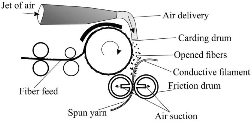
Schematic description of friction spinning.
Commingled Wrap Spun Yarns
Commingled wrap spun yarns are spun on systems described as hollow spinning systems. 40 Instead of a filament core, the core of mostly drafted slivers run through a hollow spindle without receiving a true twist. A continuous filament yarn (conductive), unwound from the bobbin attached to the hollow spindle, is helically wrapped over the drafted strand of fibers, resulting in a wrap spun yarn (Fig. 6). 37 Polyacrylic/metal wire composite yarns are produced using core spinning and wrap spinning techniques on a fancy yarn machine. 41 For manufacturing metal composite yarns, the core and wrapped yarns used are stainless steel wire and polyacrylic filament, respectively.
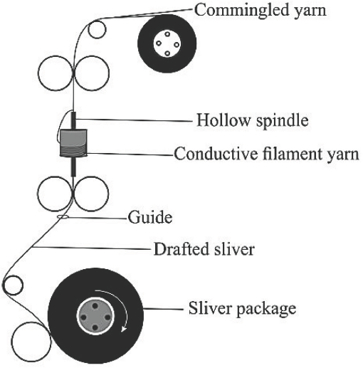
Schematic description of commingled spinning.
Core yarn spinning imparts important properties to the resultant yarn, including high strength, impressive abrasive resistance, excellent resistance to perspiration, good wash and wear performance, and good cover for otherwise fragile and brittle conductive wires. However, these yarns are deficient in areas where high electrical conductivity is required. Most applications are therefore in antistatic, electromagnetic, and fame retardant fabrics. One conductive yarn is produced by wrapping an elastomer around a silver-plated nylon filament. 42 A yarn of this kind obviously falls within the scope of core spun yarns; however, they are wrongly labeled as silver-plated conductive yarn by some commercial sources. Other core spinning techniques include Parafil wrap spinning, air-jet/vortex spinning, and Rotona core yarn spinning.
Blended Spun Yarns
The blending of different quality fibers of the same type is a well-established technique for achieving quality and economic advantages. 43 Blending of dissimilar fibers for improved appearance, comfort, performance, and for special applications is a routine practice.44,45 Blending is a process of combining two or more fibers to improve product quality.
The paramount objective of blending is to obtain a yarn with a set of properties for a predetermined end use.
For example, some blended yarns are characterized by good elasticity and conductivity. An electrically-conductive elastic blended yarn having an elastic member surrounded by at least one conductive covering filament was reported. 46 The conductive covering filament has a length that was greater than the drafted length of the elastic member—substantially, all elongating stress imposed on the composite yarn is carried by the elastic member. The elastic composite may further include an optional stress-bearing member surrounding the elastic member and the conductive covering filament. This type of yarn currently remains as prototypes, and may have potential as a good material for knitting strain sensors. Commercially-available conductive yarns in this category are predominantly core spun or commingled.
Bi-Component and Multi-Component Yarns
Bi-component fibers are prepared by extruding two polymers from the same spinneret—both polymers are contained within the same filament. Each component may have different physical or chemical properties. By introducing other materials, such as coatings, and mixing specific fillers or chemical compounds in one or both components, bi-component fibers can be enhanced. 47 Multi-component fibers are composed of more than two polymers. By co-extruding two or more polymers into one single fiber, the different properties of the polymers are exploited.
In the production of conductive yarns based on bi- or multi-component spinning, depending on the desired effect, either the metallic or non-metallic component can serve as the core, sheath, or filling. Conductive materials, such as carbon, graphene, and carbon nanotubes (CNTs), were used as fillers in recent studies. 48 Several modified filament-spinning systems (e.g., melt spinning,49,50 electrospinning, 51 and solvent spinning 52 ) were used to produce bi- or multi-component conductive yarns. In conventional spinning, the fiber mate-rial—in a molten state, a concentrated viscous liquid, or in a dry state—is extruded via an orifice. In a modified arrangement, materials of different compositions are prepared and pumped separately, and loaded into the extruding chamber for subsequent extrusion. When the setting is such that the co-extruded materials are placed side-by-side, the resultant filament becomes a side-by-side filament matrix or cross section. Several configurations of bi- or multi-component filament matrices are shown in Fig. 7.
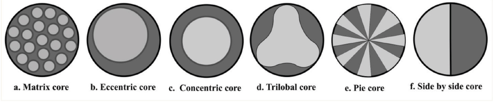
Schematic descriptions of several configurations of bi- or multi-component filament matrixes.
These types of yarns are very robust, and their characteristic functions, such as stress-strain behavior, low shrinkage, high modulus, good electrical conductivity, toughness, and solvent resistance, can be tailored. Knittable yarns suitable for strain sensing and other smart textile applications can best be produced via this technology. However, yarns produced using this technology are not yet available in commercial markets.
Inherently Conductive Polymer Yarns
Conductive polymers, or more precisely, intrinsically-conducting polymers (ICPs), are organic polymers that conduct electricity.53,54 They are materials that use conjugated polymers 55 and at least one secondary component (inorganic, organic, or biologically-active materials). They can be simply prepared using electrochemical or chemical oxidative methods. Examples of ICPs includes poly(heterocyclic) types, such as polypyrrole, polyfuran, polythiophene, poly(p-phenylene vinylene), aromatic poly(azomethine), and polyaniline (PANI).
PANI is one of the most popular intrinsically-conducting polymers (ICPs) since the 1970s.
56
Compared to other ICPs, PANI is low cost, can be easily synthesized, has tunable properties and relatively high conductivity, and is stable in air.
57
Conductive polymers based on PANI can use pure PANI or can be manufactured by adding PANI as the conductive component to the spinning solution, like traditional conductive blended fibers. Coating to effect an intrinsic polymeric reaction with already spun polyethylene yarn was reported.
56
It can be blended with other polymers such as polyethylene, polypropylene, polystyrene, soft PVC, phenol formaldehyde resins and different types of thermoplastic elastomers.
58
Although it is claimed that PANI can be used in pure form (emeraldine base form), PANI in
A new acid-solution processing route allows wet spinning of inherently-conductive PANI fibers in a one-step process. 59 This is achieved from solutions of PANI protonated with 2-acrylamido-2-methyl-1-propanesulfonic acid in dichlo-roacetic acid. The fibers are spun into various coagulation solvents (i.e., acetone, butyl acetate, and 4-methyl-2-penta-none). However, fibers produced from pure PANI are not strong enough for knitting.
Since the discovery of electrically-conductive polymers in the late 1970s, researchers have investigated ways to use these novel plastic materials that behave like metals. Many barriers have been overcome to put these materials into commercial use. Several breakthroughs also emerged with the development of nano-technology.
Most yarns based on ICPs and suitable for knitting are those produced via coating of fibers or on already spun yarns, and as fillings by introducing them into spinning solutions. Certain coated yarns exhibit quite massive depletion in conductivity because of poor adhesion after wash tests. ICPs therefore can be said to be more effective in delivering anti-static, 60 electromagnetic shielding,60,61 and thermal62,63 properties, rather than electrical conduction, in yarns.
Laminated/Coated Conductive Yarns
Yarn coating, lamination, or plating is an inexpensive way of producing conductive yarns with the widest applications. Coating applications can improve the surface properties of a bulk material, usually referred to as a substrate. A review of these coating chemistries and technologies is available. 64
Yarn coating can be accomplished via several methods including solution or dip coating, extrusion coating, plasma coating, melt coating, and electroplating and electroless plating. The chief materials used for the preparation of coating solutions and dispersions are ICPs, carbon nanotubes, graphite, grapheme, carbon black, molten metals (e.g., gold, silver, aluminum, and copper), and nano-wires.
Dip coating typically describes precision-controlled immersion and withdrawal of any substrate into a liquid reservoir for depositing a layer of material. Unwound yarns from a spool are passed through a tank to be coated with solution. They are subsequently led through a heating chamber for drying and excess moisture removal. The process ends with the winding of dried yarns on specially-designed bobbins (Fig. 8). Dip coating has been applied extensively to textiles as a finishing treatment.
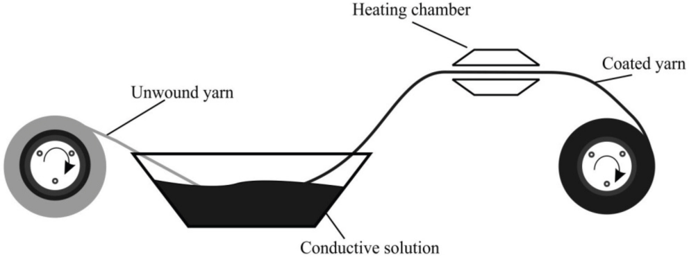
Schematic description of dip coating.
In extrusion coating, the polymer melt is directly coated on the filaments as they are extruded through the specially-designed spinneret. Extrusion coating and typical lamination are carried out simultaneously in the production of conductive fibers. The substrate is extruded in the form of a thin film and is sandwiched by the coating materials as it emerges for the orifice of the specialized spinneret (Fig. 9). These laminated films are then slit into filaments and spun into yarn.
Schematic description of extrusion coating method.
Acetate butyrate/aluminum foil is one of the popular yarns produced by this method. These yarns (e.g., Metlon reflective yarns) are used in reflective work attires. A continuous fat monofilament composed of aluminum foil is laminated on both reflective surfaces with cellulose acetate butyrate film.
Plasma coating is essentially a spray coating process. The material to be deposited is typically a powder, and sometimes a liquid, suspension, or wire. The material is introduced into the plasma jet from a plasma torch. The jet with a temperature of ∼10,000 K melts the material and propels it towards the substrate. There, the molten droplets fatten, rapidly solidify, and form a deposit (Fig. 10). Plasma coating is an extremely effective process to apply functional nano-layers on the surface of yarns. Surface of yarns and fibers are prone to dirt and oils, therefore, substrate cleaning is a very important step preceding the deposition of a thin film with plasma-enhanced chemical vapor deposition (PECVD) or sputtering. 64
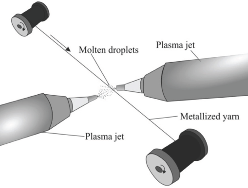
Schematic description of plasma coating method.
In a reported metallization of polyester yarns, the yarns were cleaned in situ with He/O2 RF plasma prior to their metallization with silver by magnetron sputtering. 64 Metallization via plasma spraying is cost effective and is particularly useful in electromagnetic shielding and antistatic applications.
Plasma coating has comparative advantages over conventional chemical wet processing. The process requires very low material and energy inputs, thus can be regarded as environmentally friendly. Plasma-assisted coatings also are more durable when compared to other surface modification techniques such as wet processing, because nano-scaled plasma polymer coatings get covalently attached or bonded to textile surfaces.
Plating
Plating of fibers and yarns is achieved via the twin processes of electroplating and electroless plating.64–67 Electroplating, usually referred to as “plating,” is the deposition of a metal coating onto an object by applying a negative charge on the object and subsequently putting it into a solution which contains a metal salt.
The metal salt contains positively-charged metal ions which are attracted to the negatively-charged object and are reduced to a metallic form. Many conductive yarns are made by electroplating. The metal coating should be strongly bonded to the surface of the fiber or yarn so that the coating cannot be easily removed or compromised in normal use.
A typical electroplating process involving copper and poly-amide is described as follows. 68 The polyamide is chemically treated to provide an electrically-conductive polyamide, which is subsequently immersed into an electroplating solution comprised of (a) 188–250 mL/L copper sulfate, (b) 47–78 mL/L sulfuric acid, (c) 20–200 mg/L chloride ion, (d) greater than 1.0–2.4% of Aldolyte AC-12E, (e) greater than 1.25 mL/L of Aldolyte AC-14L, and (f) greater than 3-6% Aldolyte AC-W-22. A cathode current density of 360–601 A/m2 is then applied to the electroplating solution cathode using phosphorized copper anodes to obtain a copper plated polyamide. The copper peel strength between the copper and polyamide article is >12 N/cm.
The difference between electroplating and electroless plating is the absence of external electrical power. It is a chemical or auto-catalytic process, and a non-galvanic method, that involves several simultaneous reactions in an aqueous solution, which occur without the use of external electrical power. It is sometimes referred to as chemical reduction plating, whereby catalytic reaction between metal ions or compounds and a reducing agent dissolved in an appropriate solvent react to effect plating on a substrate. It is autocatalytic in the sense that the deposited coating serves as a catalyst for continuation of the plating action. The most common electroless plating method is electroless nickel plating, although silver, gold, and copper layers can also be electroless plated.
Electroless plating typically involves cleaning the substrate to be plated and contacting its surface with a solution containing stannous chloride, other stannous salts, or a salt that has affinity for the metal that will subsequently be plated on the substrate. The treatment creates nucleating centers on the surface of the substrate which then reacts with the reducing agents contained in the electroless bath of the metal being plated to affect the plating. Other plating techniques include vapor deposition under vacuum and sputter deposition.
Conductive yarns produced under the broad category of coating, plating, or lamination processes have their individual merits and demerits. Extrusion coating proves to be very successful in producing knittable yarns for smart textile applications. The drawbacks of yarns produced in this category are poor adherence of solution or dip-coated applications when subjected to washing. Certain electroplated yarns are subsequently core or commingle spun to enhance the durability of the coating. Should the voltage used be in excess of what is required to merely reduce the electro-depositable metal ion on the filament surface, a superior bond between filament and metal layer is produced. 69 Currently, many conductive yarns are commercially produced via extrusion coating—metal corrosion is avoided by sandwiching molten metal within synthetic materials. The process also affords integration of color, a very important requirement of yarns and textiles in general.
New Conductive Material and Nano-Material Yarns
Nano-technology has revolutionized material science and related fields, including textiles. Recent developments in the textile industry include designing entirely new fibrous materials including CNTs, composites, conducting polymers, and electrospun nanofibers for smart textiles.
Yarns based on CNTs are considered potential candidates for macroscale strain sensors, due to the dependence of the electrical properties on nanoscale mechanical deformations. 70 Currently, clay, metal, and metal oxide nano-particles, and graphene, graphite, and CNTs (and allotropes) are being studied for conductive textile applications. 71 High-quality carbon fiber has an electrical resistivity of ∼1 × 10⁻⁶ Ω∙m. 72 Nano textile materials are typically classified into nano-finished textiles, nano-composite textiles, nano-fibrous textiles, and nano-enabled nonwovens. Nano-finished textiles are those textiles that have nanoscale properties imparted after the base textile is fabricated. Nano-composite textiles are composite fiber materials containing one or more nanostructured or nanoscale components, and nano-fibrous textiles are fibers characterized by nanoscale dimensions.
Nano-Finishing and Polymeric Nano-Coatings
Nano-finished yarn preparation is often done using conductive polymeric nano-coatings, a process somewhat akin to conventional textile finishing with coating dispersions (Fig. 6.) Nano-scale materials (e.g., carbon and its allotropes) can be dispersed or converted to conductive polymer composite solutions and coated on yarns to impart conductivity. 73 Other coating materials include silver nano-particles, 74 gold, and ICPs. Polymeric nano-composite coating applications have been cited, involving textile coating formulations prepared with up to 15% wt. of CNT, based on the solid weight of the binder. 75
Nano-coating is a relatively new technique in the textile field and currently under research. Because the materials processed at nano-scale have greater surface areas, results are comparatively superior to conventional coatings. Conductive finishing on yarns is more controllable, durable, and significantly enhances the functionality by incorporating various nano-particles or creating nano-structured surfaces.
Conductive Nano-Composite Textile Yarns
Polymer nano-composites are an advanced class of materials with an ultrafine dispersion of nano-fillers or nano-particles in a polymeric matrix, where at least one dimension of the nano-fillers is less than 10 nm. Typically, the individual components remain distinct and separate within the finished structure. Currently, the most researched area in multifunctional, smart fiber production is the preparation of nano-composite fibers to enhance and impart functionality on conventional textile-grade fibers. Nano-fibers with sub-micron diameter range sizes have gained popularity in some specialized technical applications.
Conductive nano-composite yarns are produced by various processes and techniques. Nano-composite synthesis typically involves the deposition of metallic nanoparticles into a dielectric matrix. Polymeric matrices are of particular interest due to their relatively low cost and easy processability. The electrical properties of such composites are closely related to the morphology of the embedded metallic nano-structures, which are dependent upon both film thickness and metal concentration. A composite yarn comprised of polyester yarns with polypropylene and multi-walled carbon nanotubes (MwCNTs) is produced via melt spinning. 76 The various components are mixed and melt extruded into a composite yarn. These yarns are quite different from bi-component and multi-component yarns because they are devoid of a dedicated core and sheath structure. Fabrication of conductive composite fibers involving polymers such as polylactide (PLA) and CNTs,77–79 polyvinyl alcohol (PVA) and single-walled carbon nanotubes (SwCNTs), 80 and conductive poly(ɛ-caprolactone), MwCNTs, and PLA 36 have been reported. Conductive nano-composite fibers and yarns possess superior conductive characteristics when compared to conventional composites. Polymeric nano-composites are rather lightweight when compared to conventional composites due to the low filler loadings. They are usually transparent, as scattering is minimized because of the nano-scale dimension involved.
Conductive Nano-Fibers/Fibrous Materials
Sub-micron diameter nano-fibers are being used in some specialized technical applications. 81 Carbon fibers are fibrous carbon materials with greater than 90% carbon content. Carbon is found free in nature in three allotropic forms: amorphous (e.g., lampblack and boneblack), graphite, and diamond. 82 A fourth form, white carbon, is thought to exist.83–85 CNTs are produced from organic matter by heating at 1000–1500 °C. CNTs have attracted research interest due to their conductivity. CNTs are being processed into fibers and yarns in several ways, including fiber extrusion from a CNT/ polymer solution, yarn spinning from a vertically-aligned array (forest) of MwCNTs previously grown on a substrate, 86 yarn spinning directly from an aerogel of CNTs as they are formed in a chemical vapor deposition (CVD) reactor, and twisting or rolling a macro-scale CNT “cotton sheet” or a CNT film with a “reticulate architecture” into a yarn. 70
Twisted CNT yarns are responsive to electrical resistance with an applied strain. 87 The resistivity of MwCNTs produced by the carbon-arc method is reported to be in the range of 5 × 10⁻⁸ to 6 × 10⁻² Ω∙m, from metallic to semiconducting, respectively. 70 Cyclic loading testing conducted on CNT yarns shows permanent strain after unloading, and the resistance at zero load increases linearly with permanent strain. However, there was negligible statistical variation in resistance, suggesting that CNT yarns could be good candidates for strain sensors. 88
The high cost and difficulties of producing the super-aligned CNT arrays has led to more interest in graphene use. Graphene, a two-dimensional monolayer of carbon atoms packed into a honeycomb lattice, is a basic building block for carbon materials of all other allotropes. 89
Various approaches to graphene synthesis includes those used for CNTs, CVD on metal surfaces, thermal decomposition of silicon carbide, mechanical exfoliation, plasma-enhanced CVD, and chemical conversion of graphite to graphene oxide. 89 Chemically-oxidized graphene can form liquid crystals in a twist-grain-boundary phase-like model, with simultaneous lamellar ordering and long-range helical formation leading to production of graphene oxide fibers. 90 The electrical resistance of graphene fiber produced by baking an aqueous solution of graphite oxide in a glass tube at 230 °C for 2 h, showed negligible variations after several reported trials in straight and in bent forms. 91 Development of highly-conductive carbon nanotube/graphene hybrid yarns has also been cited. 92 Arrays of vertically-aligned MwCNTs are converted into indefinitely long sheets by drawing. Graphene fakes are then deposited onto the sheets by electrospinning to form a composite structure that is transformed into yarn filaments by twisting. These yarns are reported to have electrical conductivity of over 900 S/cm. 93
Conductive Yarn Applications
The conductivity of conductive yarns varies and the levels of conductivity required are also dependent on specific applications. Metals generally have conductivity in the range of 106 S/ cm, and polymers from 10−14 to 10−16 S/cm. 94 Applications involving antistatic or antimicrobial properties do not require high conductivity, as compared to applications requiring electronic components, such as capacitors, wires, and electrodes. Minimal surface resistivity is usually required for the former and low resistivity (linear) for the latter. A yarn or fiber with a surface resistivity of ≤ 105 Ω/sq. is suitable for antistatic application. Applications requiring the transport of electrical signals require resistance of less than 102 Ω.
For EMS, the resistivity must be less than 102 Ω/sq. to be effective. 95 Applications of conductive textiles in modern electronics, such as touch panels, fat-panel displays, organic light-emitting diodes, e-papers, and solar cells, require opto-electrical properties such as optical transmittance (%T) and sheet resistance (Rs). 96 For touch panels, the resistance required is 300 Ω/sq., for liquid crystal displays, 100 Ω/sq., and for solar cell and organic light-emitting diodes, 25 Ω/sq. 97
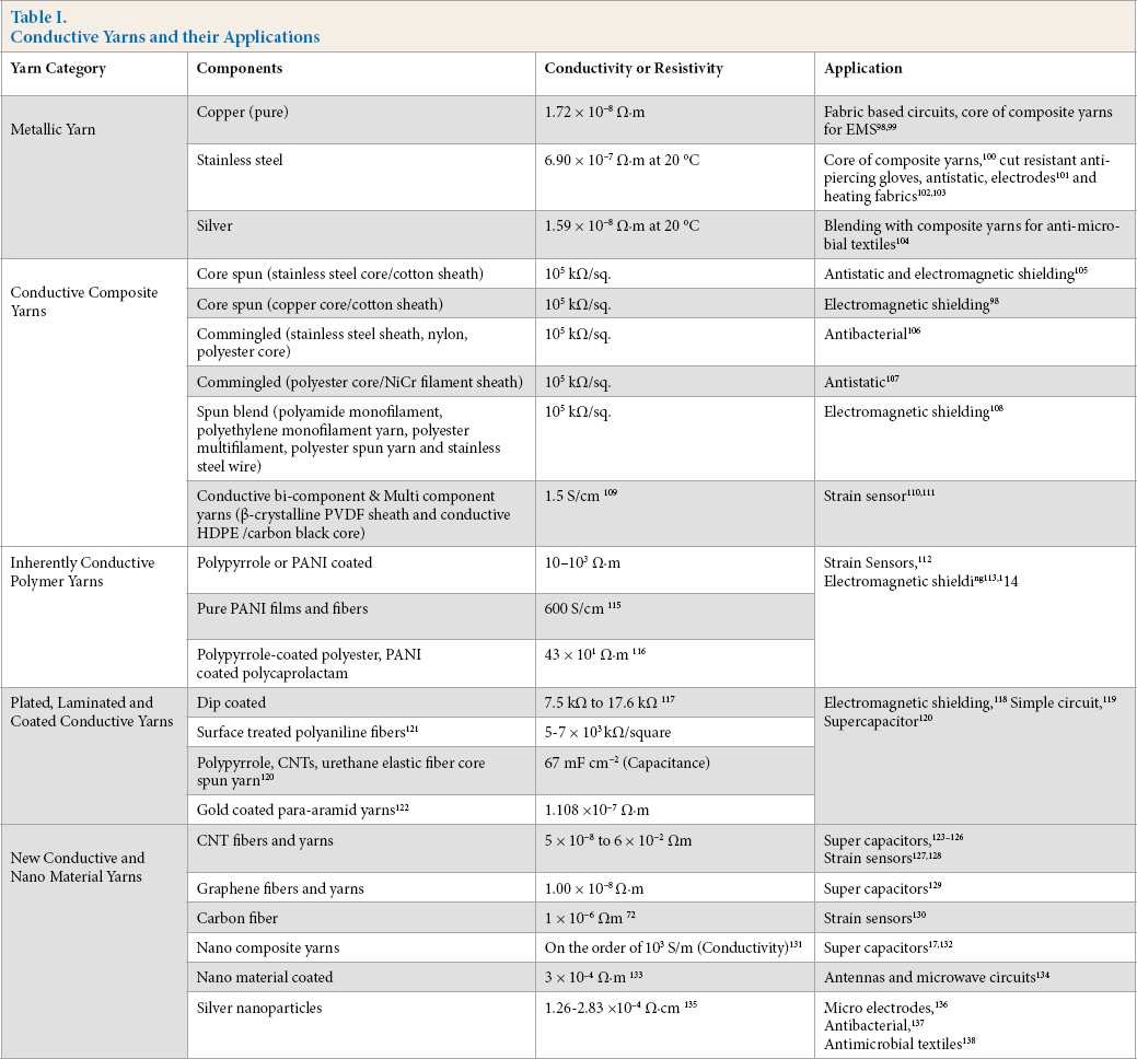
Table I summarizes the various categories of yarns, the salient components, levels of conductivity, and areas of applications.
Conductive Yarns and their Applications
Conclusion
This review discusses conductive yarns and their applications in smart textiles. Many technologies and materials are used to fabricate conductive yarns. They include metals, composites of metals and conventional textile yarns, inherently conductive polymers, yarns made by coating and lamination, and those made of new nano-materials and composites. It is generally concluded that new nano-material yarns are best suited for high-capacitance applications. With regard to composite yarns, suitable applications include imparting EMS, antistatic, and antimicrobial properties, however bi-component yarns are suitable for strain sensors. Metallic yarns usually find applications as components in core spun yarns used as EMS and antistatic fabrics. They are also applied in fabric-based circuits, but the user's skin must be protected from them. Coated yarns are quite versatile, suitable for strain sensors, EMS, and antistatic applications. Silver coated, and blended yarns with a silver component, are exceptionally good for antimicrobial applications. Yarns produced by ICPs are usually too weak for fabrics; they are therefore mostly used in coating dispersions for producing coated conductive yarns.
Even though numerous studies have been carried out on nano-material and bi-component yarns, they are not currently available on the market. The fundamental problems of wrong classification, labeling, and inadequate information regarding yarn components and make up in today's technical textile yarn market needs to be addressed. Even though some conductive yarns on the market are commingled or core spun, they are not labeled as such. Specific areas of application are also not clearly defined. Many fancy yarns with just minimal metal inclusion for aesthetic effects are even sometimes referred to as conductive yarns.
Active steps must be taken to ensure that conductive yarns are properly classified and labeled based on their physical and intrinsic properties, their mode of manufacture, and possible areas of application. The mode of manufacture obviously affects the yarn's properties. The future of smart textiles and garments including, for example, fabric-based circuits and knitted strain sensors, lies in the development of appropriate conductive yarn technology.
Footnotes
Acknowledgement
The authors acknowledge the support of the National Science Foundation of China (No. 51403080).