
Abstract
The purpose of this research was to evaluate clothing ventilation designs for their ability to reduce heat stress incurred during firefighting activities. Ventilation applications were implemented on structural turnout suits, including both active and passive systems, to determine the benefit of ventilation towards heat loss. A total of five different designs were evaluated on a sweating manikin for thermal and evaporative resistance. From these measurements, a predicted total heat loss (THL) was calculated for each design and compared back to a control suit with no ventilation. A significant improvement in heat loss was measured, specifically, with the maximum open ventilation design. Overall, ventilation designs in structural firefighter turnout gear showed a statistically significant increase in heat loss improvement for the wearer.
Introduction
Firefighters face multiple thermal hazards, including heat and fame, and high air temperature exposure, as well as high heat stress within the clothing system due to its protective properties. Structural firefighter turnout suits consist of multiple fabric layers for protection against puncture, chemicals, heat and fame, and steam.1,2 The thickness of these multiple layers hinders heat loss as sweat evaporation is reduced due to humidity and lack of air movement within the clothing microclimate.3,4 To prevent fatigue, heat exhaustion, and heat stress and stroke, a balance must be struck between the necessary level of thermal protection and required heat loss.
To alleviate the buildup of heat within a structural turnout clothing system, ventilation may be used. Ventilation may be defined as the flow of air over the skin, after passing through fabric layers and/or garment openings, increasing the potential for convective and evaporative heat loss to occur. Garment openings can be implemented into firefighter turnout suits in a variety of ways to increase air flow. Previous research, including Reischl and Stransky's studies on the ventilation of structural firefighter turnout suits, suggests some ventilation designs are more beneficial than others.1,5For example, adding vertical ventilation spacers in the side seams of the trousers 5 and coat, 2 incorporating “pit zips” in the underarm regions, 6 and incorporating an opening in the moisture barrier layer 7 may benefit firefighter suit ventilation. Designs of ventilation openings in fire fighter clothing systems can be modeled after designs found in other forms of protective clothing including military, sports, and outdoor apparel.2,3,6,8–10 It is vital to understand how and why previous ventilation designs have performed to implement those most effective in structural firefighter turnout gear.
Structural Firefighter Turnout Ensemble
Turnout gear consists of three components: a durable, protective outer shell which serves as the first line of defense against external threats; a thin, inner layer known as the moisture barrier which prevents water and liquids from penetrating through; and a thermal liner on the inside, closest to the base layers that a firefighter might wear underneath the turnout suit. The thermal liner and moisture barrier layers provide the majority of thermal protection in the three layer composite. 11
Heat Transfer
Heat is transferred through clothing by convection and evaporation. Convection relies on air exchange between the clothing microclimate and the outer environment for heat loss. 12 Two types of convection may occur: natural and forced. Natural convection occurs through fabric layers, due to existing temperature gradients, without the addition of any movement or wind. Forced convection occurs when air moves into the clothing due to wind or body movement and will accelerate heat loss to a much greater extent than natural convection alone. 6 Pumping is a type of forced convection caused by body movement.13–17 Pumping can be simulated in testing by making a manikin “walk,” although these motions are often not very close to human movement. Both types of convection should be evaluated for their individual impact on heat loss. Within forced convection, wind and body movement should be isolated separately to determine which contributes most to forced convection.
Sweat evaporation is extremely effective for heat loss 12 and is related to the heat strain of the body. It often occurs quickly when firefighters are performing heavy physical activity, especially under warm conditions.12–18 For this type of body cooling to be effective, sweat must evaporate from the skin. Therefore, ventilation should be implemented to enhance sweat evaporation.
Clothing Ventilation
The design and placement of ventilation features within the turnout suit has an impact on the amount of heat loss which can be achieved.1,3,5 There are two different types of clothing ventilation: active and passive. An active vent, for structural turnout gear, is open during normal working operations, where protection from heat and fame is not necessary, and closed during firefighting activities where direct exposure to fame may be a threat. Zipper closures that can be opened or closed based upon the need of the wearer are an example of active vents. Passive ventilation is the second type of venting that may be used. Passive vents are always in place, they are not “opened” or “closed,” and they can be located in any one of the three base composite layers. An example of passive ventilation is a vented moisture barrier. 7
Previous structural turnout ventilation research findings show less heat buildup occurred when zippered openings were placed in the seams of trousers and when garment openings were widened.1,5 The addition of mesh fabrics in sports apparel t-shirts was found to have a beneficial impact on releasing body heat, especially when placed in the side seams. 2 Vents similar to those placed in the underarms of outdoor running jackets may also benefit firefighters during non-firefighting activities, which they perform up to 99% of the time.6,19 Based on recommendations of previous ventilation research in clothing, five separate ventilation turnout suit designs were created and fabricated into separate standard garments. The purpose of this research was to evaluate the contribution of ventilation to overall heat loss within the firefighter turnout clothing system. The heat loss capability of various ventilation strategies was studied.
Methods
Five different suits, each with their own ventilation design, were tested for thermal resistance, evaporative resistance, and predicted total heat loss (THL) using a sweating manikin. A standard control turnout suit, with no added ventilation design features, was used as a baseline measurement. A thermal sweating manikin was fully dressed in a structural firefighter ensemble including trousers, coat, hood, gloves, boots, self-contained breathing apparatus (SCBA), and SCBA mask. A standard issue cotton t-shirt, athletic shorts, and socks were worn underneath the ensemble as base layers.
Sample
Garments evaluated for ventilation were all made from the same outer shell (para- and meta-aramid blend), moisture barrier (PTFE laminate), and thermal liner materials (ara-mid batting quilted to aramid facecloth). All six garments were made according to the same basic pattern. Fig. 1 shows six suits with differing ventilation designs that were tested including: 1) a standard control turnout suit, 2) a passive open vent suit, 3) a passive rivet vent suit, 4) a passive moisture barrier vent suit, 5) an active zipper vent suit, and 6) an active vertical vent suit.
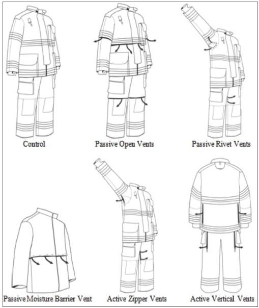
Illustration of ventilation designs in structural firefighter turnout suits including the control suit, three passive vent designs, and two active vent designs.
The passive open ventilation design sacrificed the most thermal protection as it allowed heat, fame, liquids, and air particulates to enter the clothing system. The suit was vented through all three layers, exposing the wearer's base layers to the external environment. These vents were placed around the mid-torso, upper arm, and mid-thigh regions of the suit. The passive rivet vents, placed in the underarm and groin regions, were tested under walking conditions only, as they were a minimalist approach to venting. Twelve rivets were placed in each underarm region and six were placed in the groin region, venting through all three layers of the composite.
Compared to the other four ventilation designs, the rivet vents were smaller in surface area (1-cm wide per rivet), allowing for the least amount of ventilation to potentially occur. The passive moisture barrier vent was placed in the middle layer of the coat composite only. This ventilation design created a horizontal opening in the torso of the coat's moisture barrier layer for air to flow through more freely.
Two active ventilation designs were also fabricated. The active zipper vents were placed in the underarm and groin region of the trousers. To insert the zipper, a 15-cm cut was made through all three layers exposing the wearer's base layers in these areas. One opening was made in each underarm and on each side of the inner pant seam in the groin area. A second ventilation design, the active vertical vents, was fabricated in a similar manner, but placed in different regions of the suit. Long, vertical openings were cut in the vertical side seams of the coat, from the bottom of the middle torso trim to the top of the lower hem trim. The same was done to the trousers—openings were cut starting underneath the waistline to below the pockets, on the side seams.
Vents were placed in both the coat and trousers of the turnout suit in all designs except for the passive moisture barrier vent, which was placed only in the moisture barrier layer of the turnout coat. Vents were placed through all three layers of the turnout composite, except for the passive moisture barrier vent. These six suits were tested on a sweating manikin for both thermal and evaporative resistance. Calculations were performed to determine the predicted THL of each suit.
Procedures
Evaluation of each ventilated turnout suit was completed using a sweating thermal manikin. The 34-zone model included separately-controlled heated sections with built-in pores for sweating, and a fluid pre-heater inside the mani-kin to ensure the “sweat” coming through the pores was maintained at the proper temperature. 20 The manikin was connected to a computer software program, which monitored the heaters, fluid temperature, manikin temperature, and flow set points for each zone section. The standard control and ventilated turnout suits were evaluated under the following four conditions shown in Table I.
Sweating Manikin Testing Conditions
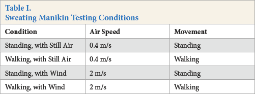
Natural convection (standing, with still air), pumping (walking, with still air), and forced convection (standing, with wind) were evaluated for each vented suit in both dry (convective heat loss) and wet (evaporative heat loss) tests. A dynamic condition (walking, with wind) was added to determine the maximum amount of ventilation achieved by the garment openings when both air and body movement occurred. The passive rivet vent suit was a minimalist approach towards ventilation, with little area of the garment actually opened for ventilation to the outer environment. Therefore, this turnout suit design was evaluated under the two walking conditions only (walking, with still air and walking, with wind) to determine if any ventilation effect occurred. For each suit, six replications (three dry manikin tests and three wet manikin tests) were performed and an average THL was calculated, for each of the four test conditions.
Sweating Manikin THL
Evaluating THL on the manikin level allowed the entire ensemble to be assessed, including pockets, accessories, boots, gloves, hood, and helmet. This method took into account the amount of body surface area covered by different materials and various numbers of layers, the ft of the garment, and the increased surface area for heat loss.21,22 TheTHL method was originally developed for use with a sweating, guarded hot plate on the fabric level only, with calculations assuming measurements were made under identical, non-isothermal conditions (25 °C/65% relative humidity (RH)). For manikin testing however, per ASTM F1291-10 Standard Test Method for Measuring the Thermal Insulation of Clothing Using a Heated Manikin, and ASTM F2370-10 Standard Test Method for Measuring the Evaporative Resistance of Clothing Using a Sweating Manikin standards, dissimilar testing environments are required.
Manikin test measurements were calculated in a 23 °C/50% RH environment for thermal resistance and a 35 °C/40% RH environment for evaporative resistance. 21 Because manikin THL calculations are based upon measurements taken in two different environments, the resulting heat loss values are predictive rather than actual measurements. 21 It is assumed in the manikin THL calculation that condensation and absorption had a negligible effect on heat transfer and the thermal and evaporative resistance of the tested fabric were independent of the ambient temperature and humidity. 21 With these assumptions in mind, the predicted THL (Qt) for a 25 °C and 65% RH environment were calculated based on the thermal and evaporative resistance (Rt and Ret) measurements from the sweating manikin according to Eq. 1. 21
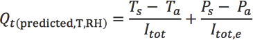
Qt(predicted, T,RH) is the predicted manikin THL for the specified environmental conditions (W/m2), T is the specified temperature condition (°C), RH is the specified relative humidity (%), Ts is the specified temperature at the manikin surface (°C), Ta is the specified temperature of the local environment (°C), Ps is the calculated water vapor pressure at the surface of the manikin (kPa), Pa is the calculated water vapor pressure in the specified local environment (kPa), Itot is the total thermal resistance of the clothing ensemble and surface air layer (°C·m2/W), and Itot, e is the total evaporative resistance of the test ensemble and surface air layer (kPa·m2/W).21,23
Statistics
To determine the statistical significance of the measured differences in predicted manikin THL, compared to the baseline control, two-sample t-tests, assuming equal variances, were performed. All data was tested for normalcy and normal distributions were confirmed through a probability plot and the Anderson-Darling test statistic. A one-way ANOVA, single factor, was conducted with each data set (for each condition) to determine if significant differences were present. If differences were identified between the results, t-tests were carried out. All sets of data in this study showed significant differences, therefore, t-tests were conducted comparing each ventilated suit to the control, and all other suits, for each of the four test conditions. A p-value less than 0.05 indicated a significant difference in THL between the control suit and the ventilated suit.
Results
The predicted manikin THL results of each suit, in a 25 °C, 65% RH environment, were compared to the standard turnout control. Tree of the five suits, including the passive open vent, active zipper vent, and active vertical vent suits, showed statistically significant improvements in heat loss while two of the passive systems did not. A graphical illustration of all six suits, under all four conditions, is shown in Fig. 2. Error bars represent standard deviation of the data and the statistical difference between suits under each condition. There were no results for the passive rivet vent suit under standing conditions because it was a minimalist approach to venting and evaluated under walking conditions only.
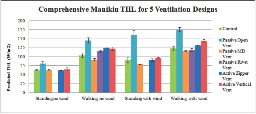
Overall predicted manikin THL results of all ventilated suits under the four test conditions, compared to the baseline control.
To further understand the differences in heat loss between the ventilated designs and the control suit, heat loss measurements were related to the surface area of the ventilation openings. Table II provides specific heat loss data for each vented suit under the dynamic test condition (walking, with wind), as well as the calculated surface area for the vent openings in each suit. The percent increase in THL between each suit under the static condition (standing, no wind) and the dynamic condition were included as well.
Surface Area of Vents and Percent Increase in THL
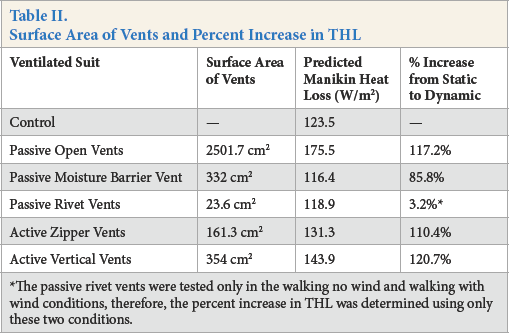
The passive rivet vents were tested only in the walking no wind and walking with wind conditions, therefore, the percent increase in THL was determined using only these two conditions.
The passive open vent design had the highest THL and the largest ventilated surface area of the five suits, leading to a 117.2% increase in heat loss when both wind and motion were added to the test condition. The passive rivet vents had the lowest ventilated surface area and a THL value less than the control suit. Both the passive moisture barrier vent and the active vertical vents had similar ventilated surface areas between 330 and 360 cm2, however, the design and placement of the vents within the turnout suit influenced the heat loss performance more than the surface area.
Passive Open Ventilation
This suit showed statistically significant (p < 0.05) greater heat loss, compared to the control, under all four test conditions. The improvement in heat loss, compared to the control, was greatest under the standing, with wind condition, where a 77% increase in heat loss was measured. A 42% increase in THL was determined under the walking, with wind condition. For this specific ventilation design, forced convection through wind was the greatest contributor to increased heat loss.
Passive Moisture Barrier Ventilation
This suit was found to have the lowest increase in heat loss, compared to the control garment, of the five designs tested. Under the walking, with wind condition, the passive moisture barrier vent had a decrease in THL of 5.75%, compared to the control under the same conditions. Under the natural convection condition, there was only a 0.95% decrease in THL, compared to the control, while there was a greater than 10% decrease (p < 0.05) in THL under the wind and pumping isolation conditions.
Passive Rivet Ventilation
The passive rivet vent had a 11.6% (115 W/m2) increase and a 3.7% decrease (119 W/m2) in THL, under the walking, with still air and walking, with wind conditions, respectively, compared to the control. The increase in THL under the pumping isolation condition was statistically significant (p < 0.05). While the THL under the walking, with wind condition was slightly less than the control, it was not a significant decrease. From these initial results, it was concluded that rivet ventilation in structural turnout garments was not suf-ficient for increasing THL or reducing heat stress.
Active Zipper Ventilation
The active zipper vent suit resulted in a statistically significant (p < 0.05) improvement in THL, compared to the control, under both walking conditions. The greatest increase in heat loss, compared to the control, was under the walking, with still air condition. Pumping effects under this condition contributed to a 21% increase in heat loss. There was a 6.3% increase in heat loss under the walking, with wind condition compared to the control.
Active Vertical Ventilation
Vertical ventilation resulted in a statistically significant (p < 0.05) improvement in heat loss, compared to the control, under the walking conditions only. Regardless of whether wind was present, results showed a significant increase in heat loss under both walking conditions. The pumping, due to walking condition, was found to be the biggest contributor of heat loss for the vertical vents. Under the walking, with still air condition, the addition of pumping, compared to the control, created a 19% increase in THL. Under the walking, with wind condition, a 17% increase in THL was observed.
Discussion and Conclusion
Results showed that three of the five ventilation designs tested were effective for improving heat loss in current structural firefighter turnout suits when compared to the control garment. Of the three passive vent designs tested, only one demonstrated a statistically significant improvement in manikin THL. The passive open vent gave the greatest improvement in heat loss of all suit designs tested, under all four test conditions.
The passive moisture barrier vent and passive rivet vent suits were not successful in increasing heat loss above what was already provided in current turnout designs without ventilation. The lack of improvement with these designs was most likely due to their placement and size. The passive rivet vents were only 1-cm wide, with a surface area of 23.6 cm2 for a total of 30 rivets placed in the underarms and groin regions of the suit. The small surface area of the rivet vents, compared to the other designs (354 cm2 for the active vertical vents and 2501 cm2 for the passive open vents) contributed to the limited effect on heat loss. The active zipper vents were placed in the same areas (underarms and groin) of the garment as the passive rivet vents, however, the surface area of these zipper vents was 161.3 cm2, compared to just 23.6 cm2 for the rivet vents. This increase in ventilated surface area in the same isolated segments resulted in a significant improvement in heat loss for the overall garment.
The passive moisture barrier vent was placed in the middle of the three layer composite, around the torso only. This passive vent consisted of a 2.5-cm wide gap, around the torso circumference of the coat (133 cm), resulting in a ventilated surface area of ∼332 cm2. The surface area was similar to that of the active vertical vents (354 cm2), but did not produce a significant increase in heat loss, due to the placement of the moisture barrier vent. While air flow may have increased through the moisture barrier vent, by sandwiching it between the thermal liner and outer shell, air was not able to escape to the external environment. Ventilation of only a single layer minimized the potential impact of the passive moisture barrier vent design. Instead, the vent should be extended through all three layers of the base composite to achieve an improvement in heat loss.
The resting position of the SCBA further decreased the ability of this vent to function properly. Future research should be completed on the trousers, with multiple vents placed horizontally along the length of the moisture barrier pant leg. This would evaluate the ability of this type of passive vent to increase heat loss.
Both of the active vent designs showed statistically signifi-cant increases in THL under the walking conditions. These vents require pumping action, through manikin movement, to effectively release heat from the body. For the active zipper vent, under the standing conditions, the lack of heat loss improvement was limited by vent placement. The underarm vents were essentially closed of in the standing manikin position, with the arms hanging down on each side. The same was true of the groin region vents. For both active vents, their success can be attributed to pumping, where air is pulled into the garment openings as the arms and legs swing back and forth.
The two active vent concepts and the passive open vent design should be implemented into structural firefighter prototypes for further evaluation on the human wear level. Future research should include the evaluation of venting multiple versus single layer systems, ventilation placement within the garment, testing in scenarios simulating other conditions beyond a structural fire ensemble, and measures of physiological responses when worn by humans.
Footnotes
Acknowledgements
This work was supported by the Department of Homeland Security, Federal Emergency Management Agency, Fiscal Year 2012, Assistance to Firefighters Grant program, fire prevention and safety [grant number EMW-2012-FP-01185].