
Abstract
Ophthalmic sonography has been practiced for more than 50 years, but it is not an area of sonography that is familiar to many physicians and sonographers. However, it can be very helpful as a means to noninvasively evaluate for specific anomalies and also assist in cases of trauma. This article has been written to describe ocular sonography and its clinical capabilities in a wide variety of settings, from an individual physician office to a busy emergency department.
Ophthalmic sonography is an imaging technique used for evaluating the structures of the eye and the surrounding tissues. It is a primary diagnostic imaging modality for the eye, and it provides a safe, noninvasive tool with instant, real-time feedback. 1 Ophthalmic sonography has been used for over a half century and continues to be an important tool to assess many types of ocular pathologies.
Historically, the eye was among one of the first organs to be evaluated with two-dimensional (2D) and three-dimensional (3D) sonography, perhaps because its regular geometry was readily interpreted on those images. 2 In addition, since the eye is such a superficial and readily accessible organ, sonography was a practical choice for diagnostic use. The first documented ophthalmic sonograms were in the 1950s, by Mundt and Hughes (A-scan) and Baum and Greenwood (B-scan). 2 Since that time, while there have been significant improvements in scanning, data processing, and image display technologies, the center frequency of ophthalmic ultrasound systems has remained at or near 10 MHz. 3 Typically, both A-scans and B-scans are performed with small, handheld pen-sized transducers that most commonly have a fluid-filled scleral shell. In addition, they may also use a water bath consisting of a membrane-enclosed tip applied to the eye after a topical anesthetic has been given. 3
In addition to A-scans and B-scans, a third commonly used technique that takes advantage of improved technology is ultrasound biomicroscopy. A-scan gives a one-dimensional view, valuable for measuring chamber depth and identifying the location of and characterizing ophthalmic structures (Figure 1). A diagnostic A-scan for identifying structure locations and depth typically uses a lower transmit frequency, in the range of 8 MHz, to maximize penetration and depth. A biometric A-scan is used to provide more detail and uses a higher transmit frequency, 10 MHz or greater, to optimize axial resolution and tissue scattering to not only precisely measure the axial length of the eye but also characterize the tissues and differentiate between normal and abnormal (Figure 2).
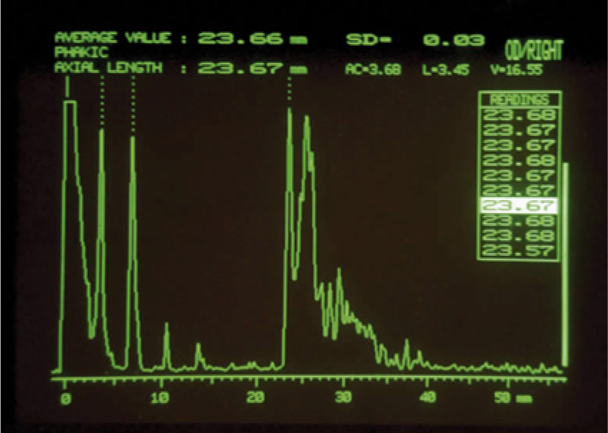
A-scan image of the normal eye showing characteristic reflectivity from internal structures; when the probe is properly aligned, the reflective signals should arise from the baseline at very nearly a right angle, as seen in the image. (Reprinted with permission from Astbury N, Ramamurthy B. How to avoid mistakes in biometry. Comm Eye Health 2006;19:70–71.)
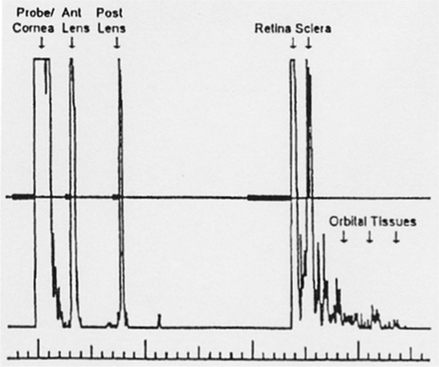
A-scan image of the normal eye with the strong internal reflections labeled for the corresponding structure; the retina and the sclera should be two distinct echoes. (Reprinted with permission from Waldron RG. A-scan biometry. http://emedicine.medscape.com/article/1228447-overview.)
B-mode imaging yields a high-resolution, real-time 2D evaluation of structures, typically used to evaluate growths and foreign bodies (Figure 3). 1 It is often used to complement or supplement a technically difficult clinical examination and allows the documentation, measurement, and differentiation of intraocular tumors. Ophthalmic sonography may also be helpful in the presence of clear media for evaluation of the iris, lens, ciliary body, and orbital structures. Clinical indications for these scans would include cataract formation and severity, intraocular hemorrhage, retinal detachment, trauma, and imaging of the optic nerve.
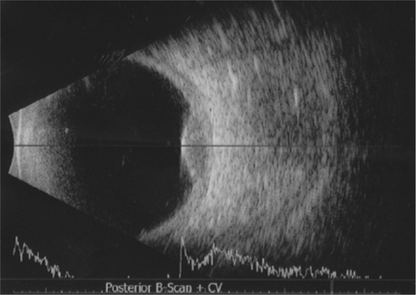
Combined A-scan and B-scan image of the eye with a relatively low-frequency probe, showing poor resolution of near-field targets and good visualization of the retina at the back of the globe where a small dome-shaped lesion is seen measuring just over 3 mm (ocular melanoma). (Reprinted with permission from Langlais S, Velazquez-Martin JP, Dubé P, Simpson ER, Leblanc G, Sideris L. Ocular melanoma in a patient successfully treated for diffuse malignant peritoneal mesothelioma: a case report. World J Surg Oncol 2012;10:90.)
Ultrasound biomicroscopy (UBM) was first developed in the 1990s by Foster and Pavlin. 2 It uses very high-resolution instrumentation with transmit frequencies in the range of 35 to 50 MHz and higher (Figure 4A,B). The transducer used for this type of examination is one that is coupled to the eye using a scleral shell that holds the eyelids open and is filled with normal saline or viscous methylcellulose for acoustic coupling. 3 This examination is most frequently used to image the anterior structures of the eye that are in the near field of more conventional sonography and not easily seen. This allows for the evaluation of a number of abnormalities such as ocular trauma, foreign bodies, opaque elements, cataracts, and intraocular pressure.
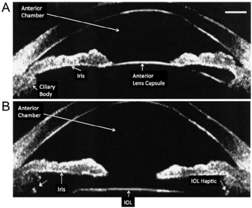
Ultrasound biomicroscopy image of the anterior segment of the eye showing the near-field resolution. (A) Normal lens and (B) intraocular lens (IOL) with small arrows showing echogenic side strut attachments (haptics).
Anatomy of the Eye
The sonographic images of the eye are divided into two chambers, anterior and posterior (Figure 5). In the anterior chamber of the eye is the small, asymmetric cavity of the globe that includes the lens and all structures anterior to the lens. The anterior chamber is defined by structures superficial to the iris (behind the cornea) and contains the aqueous humor. The posterior chamber is defined as structures deep to the iris and contains the lens and vitreous humor. 4
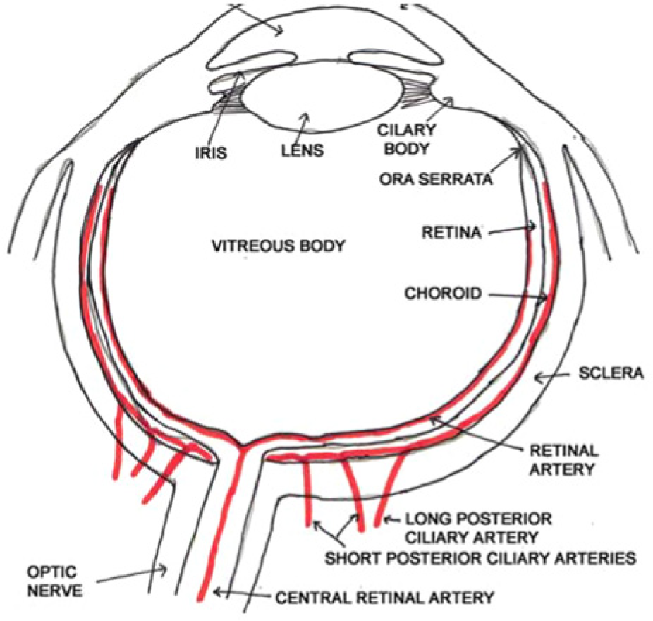
Normal anatomy of the eye. (Reprinted with permission from Southern S. Ultrasound of the eye. Australasian J Ultrasound Med 2009;12(1);32–37.)
To describe these anatomic locations in sonographic terminology (Figure 6), it is easiest to begin with the most superficial thin convex membrane, which is followed by the anechoic fluid of the anterior chamber, the aqueous humor. The iris is represented by an echogenic linear band that originates from the edge of the eye.5,6 The next region is the posterior chamber, which is the convex membrane of the lens, followed by the anechoic space of the vitreous body. The vitreous body is a jelly-like substance that presses sternly against the retina to guarantee contact with the choroid and sclera. Next is a three-layer echogenic membrane, consisting of the sclera, choroids, and finally the retina. Although this three-layer membrane can be seen by high-resolution sonography, it can be difficult to distinguish between the actual layers. The next area visualized is a hypoechoic shadow that represents the optic disc, followed by the optic nerve. This last area is one of the most important in emergency cases. The retina should be firmly attached to the optic disc posteriorly and the ora serrata anteriorly. The retina and choroid have their own blood supply; however, the retina is actually supplied by the central retinal artery, which enters through the optic nerve while the choroid is perfused by the short and long posterior ciliary arteries. When evaluating these vessels, reduced velocity, particularly the end-diastolic component with increased resistance to flow, are the typical flow patterns that normally occur but may be exaggerated in some pathologic states.7–9 This is helpful in identifying flow abnormalities when using color and spectral Doppler in the diagnosis and management of vascular conditions within the eye.
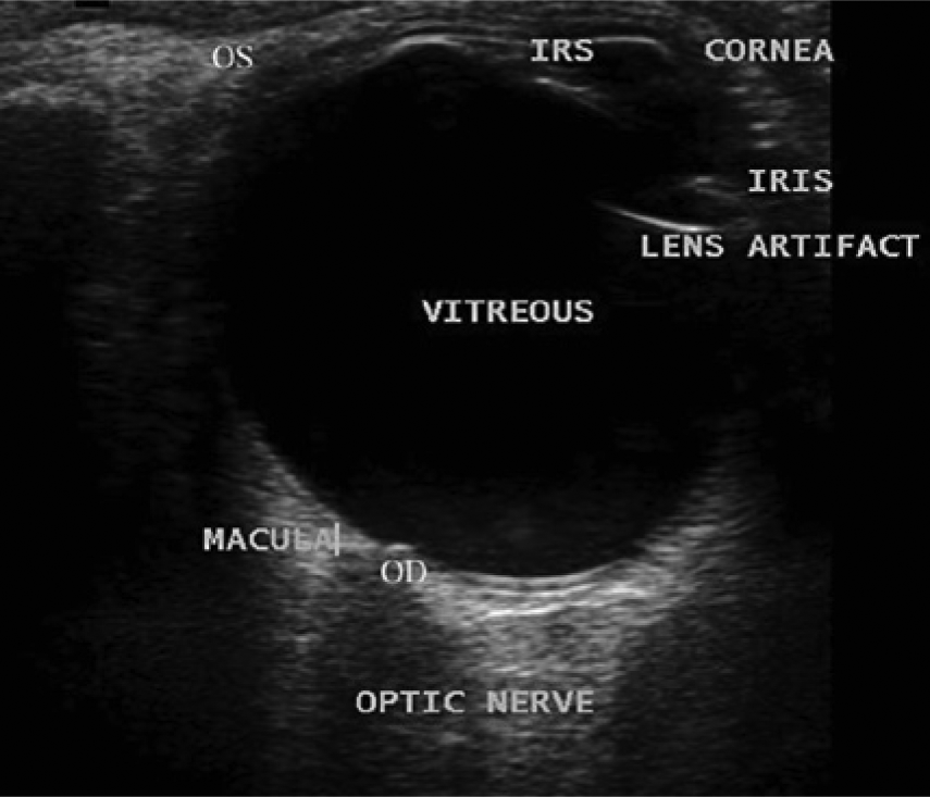
Sonographic appearance of the normal eye. (Reprinted with permission from Southern S. Ultrasound of the eye. Australasian J Ultrasound Med 2009;12(1);32–37.)
Ophthalmic Sonography Credentialing
All certification and examinations are approved through The Joint Commission on Allied Health Personnel in Ophthalmology (JCAHPO; www.jcahpo.org). The objective of certification is to ensure that individuals are qualified by training and experience to practice ocular sonography in any health care facility. To become credentialed as a Certified Diagnostic Ophthalmic Sonographer (CDOS) in ophthalmic sonography, there are three possible choices, depending on the level of education or training (see Table 1). 10
Prerequisites for Certification as a Diagnostic Ophthalmic Sonographer by the Joint Commission on Allied Health Personnel in Ophthalmology (JCAHPO).

CDOS, Certified Diagnostic Ophthalmic Sonographer; CMA, Certified Medical Assistant; COA, Certified Ophthalmic Assistant; COMT, Certified Ophthalmic Medical Technologist; COT, Certified Ophthalmic Technician; CRA, Certified Retinal Angiographer; OMP, Ophthalmic Medical Personnel; RDCS, Registered Diagnostic Cardiac Sonographer; RDMS, Registered Diagnostic Medical Sonographer; ROUB, Registered Ophthalmic Ultrasound Biometrist; RT(S), Registered Technologist, Sonography.
Clinical Utilization of Ophthalmic Ultrasound
There are currently two clinical sites that benefit most from the use of ophthalmic ultrasound. The first of these is in ophthalmologists’ offices. In most cases, incomplete visualization of the eye during clinical evaluation necessitates sonography. At the time of the procedure, the typical abnormalities that are visualized are cataracts and retinal detachment. These office-based procedures may be done by an ophthalmic sonographer, but they might also be done by a cataract/refractive surgeon, a pediatric or general ophthalmologist, a retinal specialist, an oncologist, or a neuro-ophthalmologist.
The second primary clinical application of ophthalmic ultrasound is in cases of ocular trauma, usually in an emergency department. A significant difference in this setting will be in the equipment used. Instead of an office-based machine developed specifically for ocular needs, because of the equipment that is usually available, it is likely that a general-purpose ultrasound machine will be used in the emergency setting. In addition, it is not common for an ophthalmologist to be on call when an ocular injury presents to the emergency room. It will be up to either an emergency physician on staff or credentialed sonographer to carry out the ocular sonography, neither of whom is likely to have significant experience in using sonography to examine the eye. Instead of a small, pen-like transducer designed specifically for ocular applications, an available linear transducer, with a frequency varying between 8 and 17 MHz and an array length of 2 to 3 cm, is placed on top of the eyelid with copious amounts of coupling gel.
For these reasons alone, ocular sonography is not widely used in emergency rooms. It has been documented, however, that emergency ocular sonography can be quite helpful in many severe cases. A number of studies have shown that elevated intracranial pressure (ICP), often a fatal condition in head trauma patients, can be identified and documented using sonographic imaging and measurement of the optic nerve sheath.11–13 This is a very rapid technique to diagnose elevated ICP; when done by experienced sonographers, the time spent is significantly less than it takes to complete computed tomography (CT) or magnetic resonance imaging (MRI). It is only necessary to measure the optic nerve sheath diameter (ONSD), which correlates directly with ICP when one takes into account head circumference, height, and age; because it uses sonography, the measurement can be repeated as often as necessary (Figure 7). Published studies have shown that ONSDs greater than 4.0, 4.5, and 5.0 mm have the potential to predict elevated ICP in infants, children, and adults, respectively.12,13 The underlying physiologic mechanism relies on the fact that the optic nerve sheath connects with the subarachnoid space and is easily distended; increases in ICP lead directly to dilation of the optic nerve sheath. For patients presenting to the emergency department with possible head trauma and exhibiting nonspecific symptoms such as behavioral changes, headaches, lethargy, numbness, eye movement problems, double vision, seizures, and vomiting, this rapid measurement will provide diagnostic data regarding intracranial pressure.
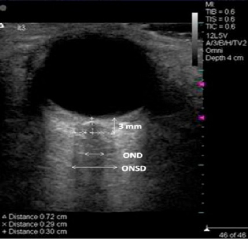
Sonographic image showing measurement of the optic nerve diameter (OND) and optic nerve sheath diameter (ONSD).
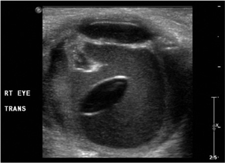
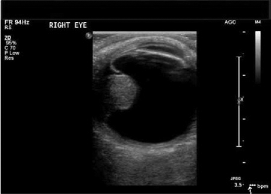
A second commonly seen entity in the emergency setting is loss of sight secondary to retinal detachment, a break or a tear in the retinal epithelium (Figure 8).14–18 The most common symptoms are seeing floaters or flashing lights within the eye. 19 If the patient experiences a shadow or curtain that affects any part of the vision, this can indicate that a retinal tear has progressed to a detached retina, a true medical emergency that must be treated quickly to avoid permanent loss of vision. Typically, the first evaluation done is direct examination of the retina using an ophthalmoscope. In many cases, this may be difficult, particularly in trauma patients or in the presence of an intraocular hemorrhage. Sonography readily allows proper visualization of the posterior segment of the eye. The sonographic appearance of retinal detachment is typically nonlayering, low-level echoes within the vitreous body that are unattached to the periphery of the globe.15,16 Retinal detachment is seen usually in two different instances. The first is an older individual whose vitreous detaches due to age, causing tiny, horseshoe-shaped holes that allow fluid to pass into and accumulate in the subretinal space. 15 It can also be found in patients who have experienced trauma. 16 Regardless of the cause, retinal detachment must be diagnosed and treated rapidly to prevent monocular vision loss.17,18 An example of vitreous hemorrhage is shown in Figure 9, where the hemorrhage can be clearly seen by its increased echogenicity within the vitreous. Vitreous hemorrhage may be a result of a variety of causes, including diabetic retinopathy, trauma, a retinal tear or detachment, vitreous detachment, and retinal vascular occlusion.20–22
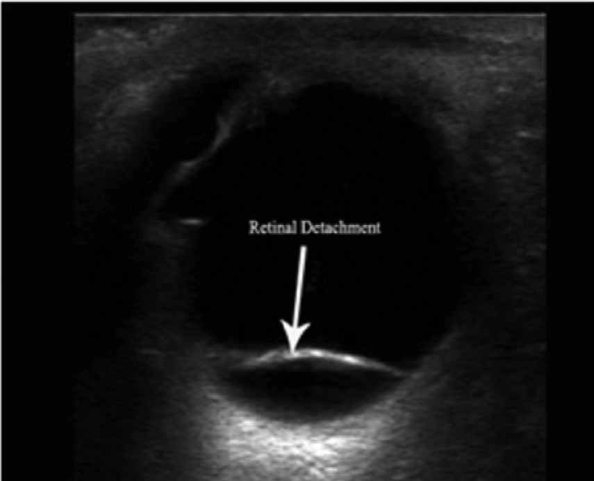
Sonographic image of a posterior retinal detachment. (Reprinted with permission from ultrasoundvillage.com/imagelibrary/cases/.)
Sonographic image following ocular trauma showing a lens dislocation and associated vitreous hemorrhage; the outline of the displaced lens is clearly seen and the hemorrhage is very distinct by its echogenicity from normal anechoic vitreous. (Reprinted with permission from Imran S, Amin S, Daula MIH. Imaging in ocular trauma optimizing the use of ultrasound and computerised tomography. Pak J Ophthalmol 2011;27(3):146-151.)
An emerging area of application of ocular sonography is the diagnosis of a variety of ophthalmic tumors.23–26 Figure 10 shows a large, solid mass within the vitreous that in this case represented an ocular choroidal melanoma. This relatively rare type of cancer is found in the uvea of the eye, which includes the iris, the muscle in the eye (ciliary body), and the layer of tissue in the back of the eye (choroid). A wide variety of other applications of ocular sonography, both as a clinical tool and a research tool, have been reported in the literature as well, including evaluation of patients with glaucoma, identification of ocular foreign bodies, diagnosis of a variety of acute and chronic problems, and even many veterinary applications.27–30
Sonographic image of an ocular choroidal melanoma in the vitreous (posterior) chamber. (Posted to http://www.youtube.com/watch?v=IApnk3wUxxs by ultrasoundpaedia.com.)
Conclusion
Sonography offers a number of advantages over other imaging techniques for the rapid diagnosis of many ophthalmic abnormalities, both in the office setting and in the emergency department. Ocular sonography also offers a rapid, noninvasive means of estimating intracranial pressure in patients with known or suspected head trauma. As even higher probe frequencies become available for routine clinical use, the application of ocular sonography can only continue to become more widespread. Its principal limitation at this time appears to be a lack of familiarity with the technique on the part of physicians and sonographers.
Footnotes
Declaration of Conflicting Interests
The author declared no potential conflicts of interest with respect to the research, authorship, and/or publication of this article.
Funding
The author received no financial support for the research, authorship, and/or publication of this article.