
Abstract
In the context of packaging with films, specific mechanical properties are of paramount importance. This can be achieved through the implementation of optimized manufacturing processes and the efficient utilization of raw materials. The foam extrusion process has the potential to enhance material efficiency. The foam structure impacts the mechanical properties due to replacing force-conducting material. Blown film extrusion represents a predominant production process in the packaging field, offering the potential for cost-effective mass production. Integration of these processes gives rise to intricate behavior patterns, attributable to interactions between the conditions governing the blown film and those governing foam extrusion. This affects the density reduction and the mechanical properties of the material. This study’s objective was to identify the significant parameters affecting mechanical properties and to gain insight into the mechanisms influencing the foam blown film process. The results demonstrated that combining foam and blown film extrusion markedly reduces the resulting film density, with a potential savings of up to 40% in plastic at 7% blowing agent content. The optimal conditions to produce small-cell foam structures include high die pressure gradients, which can be achieved by lowering the blown film die head temperature or increasing the mass flow rate of the foamed middle layer. Tensile stress and Youngs modulus decrease with increasing blowing agent content, as the gas-filled cells reduce structural integrity. Thinner films often show higher tensile strength due to better molecular orientation. At the same time, the mass ratio influences the mechanical properties by changing the polymer structure and cell distribution, which optimizes or weakens the mechanical properties. The study presents significant insights into the blown film foam extrusion process and investigates the correlations between density reduction and the resulting mechanical properties.
Keywords
Introduction
Plastic films are used in many areas nowadays. From simple agricultural covers to packaging applications and medical products, the film properties requirements vary. The mechanical properties of the film play a particularly important role in packaging. 1 These properties achieved by a film product should be realised as economically as possible. Therefore, it is essential to optimise the manufacturing process and the raw material usage. Consequently, the product should be as ecologically sustainable and resource-saving as possible. 2 Foam extrusion offers the possibility of increasing material efficiency by replacing plastic with gas bubbles. Foamed plastics also have good damping and insulating properties. 3 These advantages, which go beyond pure density reduction, have led to the widespread use of plastic foams and a steady increase in production volumes. 4 Many new thin foams for packaging have also been developed in recent years, including labels, tamper-evident seals, pearlescent-coloured wrapping paper and airline tray liners, demonstrating the wide range of applications. 5 However, the foam structure negatively effects the plastic mechanical properties, as force-conducting and resistant material is replaced by gas. 6 The plastic foaming is technically realised by using a blowing agent in the plastic melt, which forms a foam structure at the die outlet. As previously mentioned, thin foams are already being used in the packaging sector. The co-operation between Dow and Mucell should be mentioned here in particular. Mucell was granted a licence for Dow’s thin foamed films patents in 2012 and can use its foaming technology to produce foamed flat films in all applications using a physical process. 7 A second important processing method in the packaging industry is blown film extrusion. This process can be used to produce films as a mass product at low cost. By combining different materials in the coextruded film layers and by controlling the process conditions, the the blown film properties can be customised. 2 Combining both processes is realised by foaming the blown film middle layer. This makes it possible to make a high-throughput manufacturing process in the plastics industry more sustainable by saving raw materials. The combination also makes it possible to develop products with new properties.
State of the art
The blown film process conditions and foam extrusion interact with each other and result in complex process behaviour. These conditions have an influence on the density reduction and the detrimental reduction in mechanical properties and must be considered for the optimisation and configuration of the foamed blown film process.8,9 The most important influencing factors are explained in more detail below.
Blowing agent content
If a foamed product is produced, the blowing agent content can also be varied. 6 The required blowing agents are introduced into the melt of the desired film layer either physically or chemically. 10 In this study, a chemical blowing agent is used (see material and method). The blowing agent content is the mass proportion of the blowing agent that is added as a masterbatch to the plastic pellets of the layer to be foamed. The proportion is responsible for the amount of gas and nucleating agent in the melt. 6 If too little is added, there is insufficient density reduction, as only individual, distant foam cells are formed. If the proportion is too high, undissolved gas remains in the melt, which leads to large, unstable gas bubbles. 7 In general, an increasing blowing agent content leads to an increase in cell density and a decrease in film density. 11
In the blown film extrusion process, many process conditions must be precisely adjusted to produce a film product. With existing machine technology, the following parameters are varied by the system operator to enable high-throughput production and achieve the desired film properties. 2
Blown film die temperature
The melt thermal energy is influenced by the extrusion die temperature. At a lower processing temperature, the melt has a higher viscosity. 2 In addition, a lower cooling capacity is required after the die outlet to reach the crystallite melt temperature, as the heat in the melt is lower. At lower temperatures, orientations introduced by taking off and blowing on the melt tube have a shorter relaxation time. This leads to a higher degree of orientation in the film. The molecules have a stronger order. As soon as the film is heated above the softening temperature again, this order becomes apparent as shrinkage. Strongly orientated macromolecules ensure higher mechanical strength of the films by building up a crystallite structure. 12
The temperature effects on the foam formation properties and nucleation can be explained using the classical foam formation theory. 6 A lower temperature leads to a higher blowing agent solubility but also to a lower blowing agent diffusion rate in the melt. 13 Lowering the temperature increases the melt viscosity and the shear energy occurring in the die increases. This reduces the critical radius for nucleation growth and increases the number of stable nuclei, so that the nucleation rate and consequently the cell density increases. 14 The blown film die temperature or melt temperature in this range also influences the foam cell expansion at the outlet. Cell coalescence and cell collapse significantly determine the resulting cell density. Coalescence occurs when two neighbouring cells touch each other. A difference in internal pressure causes the blowing agent to diffuse from the small cell into the larger cell until the small cell has disappeared. Moreover, cell collapse occurs during the foam expansion after the die exit. When thin cell membranes are formed, they are subjected to high elongation stress. If the permissible elongation is exceeded, the cell wall ruptures. Lowering the temperature reduces the influence of both effects. 15 However, if the temperature is too low, foam growth is inhibited. 16
Film thickness
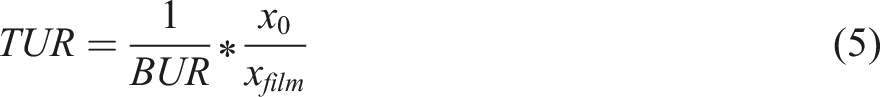
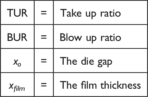
The thickness is a key film characteristic and is usually determined by the film application. It also requires a process that can produce a film with a specific and constant thickness. The film thickness is controlled by adjusting the take-up speed. The ratio of the melt speed at the die outlet and the take-up speed above the frost line is known as the take-up ratio (TUR). This is adjusted to maintain thickness and is always greater than one. Thin films are produced at high TURs. The TUR influences the film stretching in the longitudinal axis. 2 In foam films, the foam cells are also stretched in the longitudinal direction, which results in larger cells. 6 On the one hand, this stretching results in a lower cell density, as there are fewer cell walls on the same surface area. On the other hand, the combination with the film width causes a change in the cell aspect ratio, which influences the mechanical properties. 17 In general, smaller cells achieve higher mechanical properties. 18
The thickness has a significant influence on the mechanical properties of the film. Thin and therefore highly stretched films have a significantly higher strength compared to thick films, as they cool down more quickly at the die outlet due to the lower amount of heat they contain and the above-mentioned orientations freeze. 19 This is clearly shown by a high longitudinal shrinkage. Thick films, on the other hand, exhibit a higher degree of crystallisation, as the slower freezing enables the formation of larger crystallites. This leads to harder, but also more brittle films. 12
Film width
The film width is another property that is usually determined by the product specifications. The film width is controlled by the volume of supporting air in the film tube. The ratio of the die outlet diameter to the film bubble diameter above the frost line is known as the blow-up rate (BUR). The BUR has a decisive influence on the film stretching transverse to the extrusion direction. 2 In foam film extrusion, the foam cells are also stretched transversely to the extrusion direction, achieving the same effects as with the film thickness, but in a different orientation. 6
At high blow-up ratios, the macromolecules orientate themselves transverse to the extrusion direction. Biaxial stretching occurs together with the TUR. This affects the film mechanical properties perpendicular to the extrusion direction and is associated with high transverse shrinkage. The strength therefore increases significantly transversely to the extrusion direction at high BURs and decreases slightly in the longitudinal direction.2,12
Blower output
The blower output determines the air flow speed of the external convective film cooling. Therefore, the dissipated heat output also depends on the blower output. The the blower output cools the film tube quickly in order to enable a high mass throughput of the extrusion process and high orientations. 1
Cooling the film down to crystallisation temperature and reaching the frost line stabilises the foam. Slow cooling results in a long growth phase and forming larger cells with low film density. Significantly larger aspect ratios are also obtained if the cells are allowed to cool slowly because the cells had more time to deform during stretching. 16
Mass throughput ratio
The mass throughput ratio relates the extruder mass throughput for the individual layers of a multilayer film to each other. For three-layer films, the throughput ratio is specified as a multiple of the lowest extruder mass throughput for each extruder. For example, an ABA-film with a 1:2:1 mass ratio, the throughput for the A layers is 5 kg/h and 10 kg/h for the B layer if the total throughput is 20 kg/h. For compact films, the mass throughput ratio corresponds approximately to the layer thickness ratio. With foamed film, the layer thickness ratio depends on the degree of foaming. The layer characteristics determine which layer properties predominate in the final product. The middle layer mass throughput therefore has a considerable influence on the foam structure, particularly for foamed films. By increasing the foam proportion in the overall film structure, compact, force-absorbing and force-conducting material is reduced, which causes a reduction in the resistance forces and reduces the mechanical properties. The mass throughput itself also influences the film properties. On the one hand, with increased mass throughput, the TUR must be adjusted to achieve a constant film thickness, which leads to increased orientation. With foam extrusion, the mass throughput has an effect on the resulting die pressure and the flow rate. At high throughput, a high-pressure gradient is generated, which enables a fine-cell foam structure.
Aim and Scope of the study
This work’s main objective is to determine the correlations between the process conditions and the foamed film mechanical properties. The interactions between blown film extrusion and foam extrusion in terms of their parameters and phenomena have not yet been scientifically investigated. This study pursues three research objectives, which are formulated as research questions: 1. With the help of statistical experimental designs, can significant parameters that influence the mechanical properties be determined? 2. Are the mechanical properties mainly determined by the orientations introduced in the blown film extrusion process or mainly by the foam structure? Or do both processes contribute? 3. Which specific process parameters can be optimized to enhance product sustainability while ensuring adequate mechanical performance for its intended application?
In order to answer these questions, with the aid of a Design of Experiments (DoE), a test plan is developed in which the process conditions are varied in several stages. In practical tests, film samples are produced according to this test plan and the mechanical parameters are determined using standardized test methods. The effects and interactions of the process conditions on the mechanical parameters are evaluated by statistically analysing the test results. The result is to identify the effects that have a relevant influence on the mechanical film properties and provides information about the unknown correlations in this combined foamed blown film process.
Material and method
Extrusion line
A KFB 45/600 blown film line from Kuhne Anlagenbau GmbH, St Augustin, Germany, is used. The line enables three-layer film extrusion. The middle layer extruder is a 35 mm extruder with L/D = 20. The two outer layers use two 45 mm extruders with L/D = 24. All extruders are equipped with three temperature control zones with a water-cooled grooved bush in the feed as well as mixing and shearing elements at the end of the screw. Furthermore, all extruders have gravimetric throughput controls from PlastControl GmbH, Remscheid, Germany. The outer layer extruders each deliver a 5 kg/h mass throughput of. The middle layer mass throughput is adjusted in 5 kg/h multiples based on the test plan. The three extrudates are each formed into a annular melt tube in the radial spiral mandrel die. The die outlet outer diameter is 80 mm. The die gap width used is 0.5 mm. The die also has a 45° angle inlet and a 3.4 mm long parallel zone. In preliminary tests, this die was characterised by its high-pressure gradient, low cell stretching and a stable process. 20 A combined pressure and temperature sensor DTA250 from Gneuss, Bad Oeynhausen, Germany, is installed 60 mm upstream of the die outlet to record the die pressure difference and the melt temperature.
The convective heat extraction from the film tube is achieved by a tempered cooling air flow. The air flow is tempered with a cooling unit from LAUDA Dr R. Wobser GmbH & Co KG, Lauda-Königshofen, Germany. The air temperature control is set to 18°C before entering the cooling ring. The cooling air temperature also has a major influence on the relaxation of the orientation and the foaming process. In this test series, however, only the air flow rate is varied. The fan power and thus the air flow rate is set according to the test plan. As the air flow rate on the extrusion line is set as a percentage of the maximum fan power, the air flow rate was measured, and a calibration curve was then created. The fit is made with: air flow rate (m3/s) = 0.0021∗fan power (%) +0.006. The film width is measured inline in the film take-off with a capacitive width measuring device from Hch. Kündig & Cie AG, Rüti, Switzerland.
Materials used
In all three layers low-density polyethylene (PE-LD) 2102N0W 21 from SABIC, Riyadh, Saudi Arabia is used. PE-LD is well suited for blown film and foaming. This plastic is a general-purpose class and contains the standard additives provided by the supplier. 21 The 2102NOW is not a special foam plastic but has shown good foamability in preliminary tests. 22 The melt flow rate of the material is 2.5 g/10 min (190°C and 2.16 kg) and the density is 0.921 g/cm3.
A mass proportion of a chemical blowing agent specified in the test plan is added to the middle layer as a masterbatch. The weight percentage refers exclusively to the middle layer. If the throughput ratios are adjusted, the blowing agent proportion in relation to the total film composite changes. Hydrocerol CF 40 E from Avient, Avon Lake, Ohio, USA is used for this purpose. Hydrocerol is an endothermic chemical blowing agent that is particularly suitable for producing fine-cell foams. 23 It also serves as a nucleating agent due to the resulting residues, which have a nucleating effect. 24 In order to guarantee that the blowing agent completely thermally decomposes, the middle layer temperature profile is selected to be higher than the outer layers. According to the manufacturer, a maximum gas yield is achieved from 220°C mass temperature. 23 The temperature control in extruder B is kept constant across all test points and is set at 220°C in the feeding zone and 230°C in the transition and the metering zone and also the melt pipe to the blown film die.
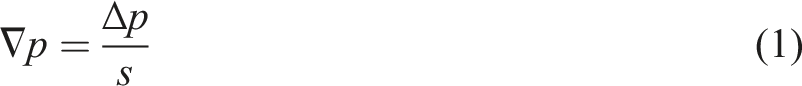
Determination of the die pressure gradient
Determining the density
Tensile test
To quantify the mechanical load capacity, tensile test according to DIN EN ISO 527-3 are performed using a Zwick Z10 universal testing machine from ZwickRoell GmbH & Co KG, Ulm, Germany. 25 Five specimens per test point are tested in machine direction (MD) and five specimens in transverse direction (TD). Type 2 rectangular specimens with a width of 15 mm are tested. 25 The tensile stress and the Young’s modulus are determined as characteristic values.
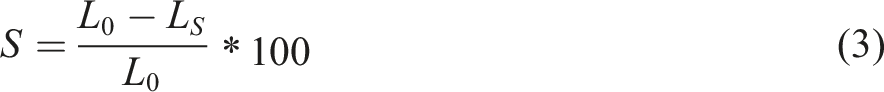
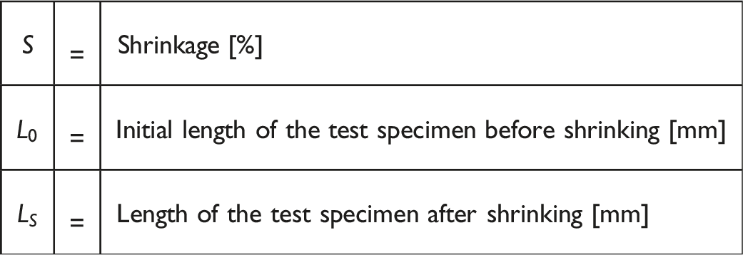
Shrinkage test
Evaluation
After carrying out these measurement procedures, each test point can be assigned six key performance indicators. The test series is analysed using the Minitab statistics programme from Minitab Inc, State College, Pennsylvania, USA. The significance of the test data is determined and then the effects and interactions of the parameters on the target variables are analysed. In order to present all main effects clearly in one diagram, the abscissa in the main effect diagrams is shown without units. Only the step variation from “−1” to “0” to “1” is shown. These represent the factorial point heights of the individual factors. For example, the step height “0” for the blown film die temperature factor describes the mean value of the experimental design at 185°C, while the step height “1” represents the temperature of the upper factorial level, namely 194°C. The upper star point is at 2.82843 times the factor levels or 230°C.
The test series is used to analyze the influence and correlations between the process conditions and the various key performance indicators (KPI) (density reduction, Young’s modulus, tensile strength, shrinkage). The influence of foam formation and the orientations introduced can be analyzed using available software.
Experimental design
The experimental program choses is a central composite design (CCD) design. It combines the corner points of a full factorial experimental design with an outside star. In addition, the star also contains a central point at which all factors are averaged. The star points are located at the distance of the corner points
Independent factors with coded and actual levels.
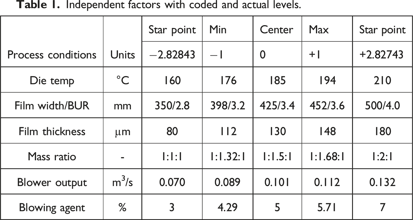
The test plan results in 12 star points, 64 corner points and one central point, which is run twice for validation. The test plan therefore provides for 78 treatment combinations: The entire test plan with all settings of the process conditions can be found in the table in the Supplemental Material. The blown film die temperature and thus also the temperature of the outer layer extruders are regulated via the system control in all zones with the characteristics specified in the test plan. The film thickness is adjusted by varying the TUR at a constant mass throughput. When varying the mass throughput ratio, the throughputs of the two outer layers of the three-layer film are kept constant. Only the throughput of the centre layer is adjusted according to the ratio.
Results
The main focus for using foam extrusion in the blown film process is on saving material by reducing the density. Therefore, in addition to the mechanical properties, the influence of the process conditions on various KPIs (Density reduction, Young’s modulus, Tensile strength, Shrinkage was analysed: The measured values of the KPIs of all test points with allocation can be found in the table in the supplementary material. In the process, the significant parameters should be determined and the effects should be correlated with the orientations introduced or the foam formation.
Effect of the process conditions on the density
Using density as an example, the procedure for analysing the significance and residuals of the regression model is presented. This procedure was carried out for each effect calculation and only the significant process conditions are presented below when analysing the effects.
Using the Minitab statistical software, a calculation model was generated using the input data consisting of parameter size and the resulting density by means of multiple regression. This model represents the mathematical relationship between factor and target variable as accurately as possible. The model should only contain factors that make a significant contribution to the accuracy of the model (Significance level: 99.5%). 28
In order to exclude these statistically insignificant variables from the model, the backward elimination method can be used. The procedure first creates a model of all possible variables. In iteration loops, the statistically least significant factor is removed and a new model is created without it until only statistically significant variables are included in the regression.
29
The regression model generated for the density using backward elimination provides the Pareto diagram shown in Figure 1. This clearly shows that only the factor blowing agent content, the interaction mass ratio∗blowing agent content and the quadratic interaction of the film thickness with itself are statistically significant, as their standardised effect has exceeded the significance threshold of 1.993 which depends on the effect level, the confidence interval of α = 0.05 and the number of parameters and is calculated by Minitab. Due to the influence of the factors mass ratio and film thickness in the interactions, they are integrated into the model even though there is no statistical significance. In order to assess the model, a detailed examination of the residual diagrams must then be carried out. Pareto diagram for the significance of the process conditions on the density (significance threshold of 1.993 at a significance level of 99.5%).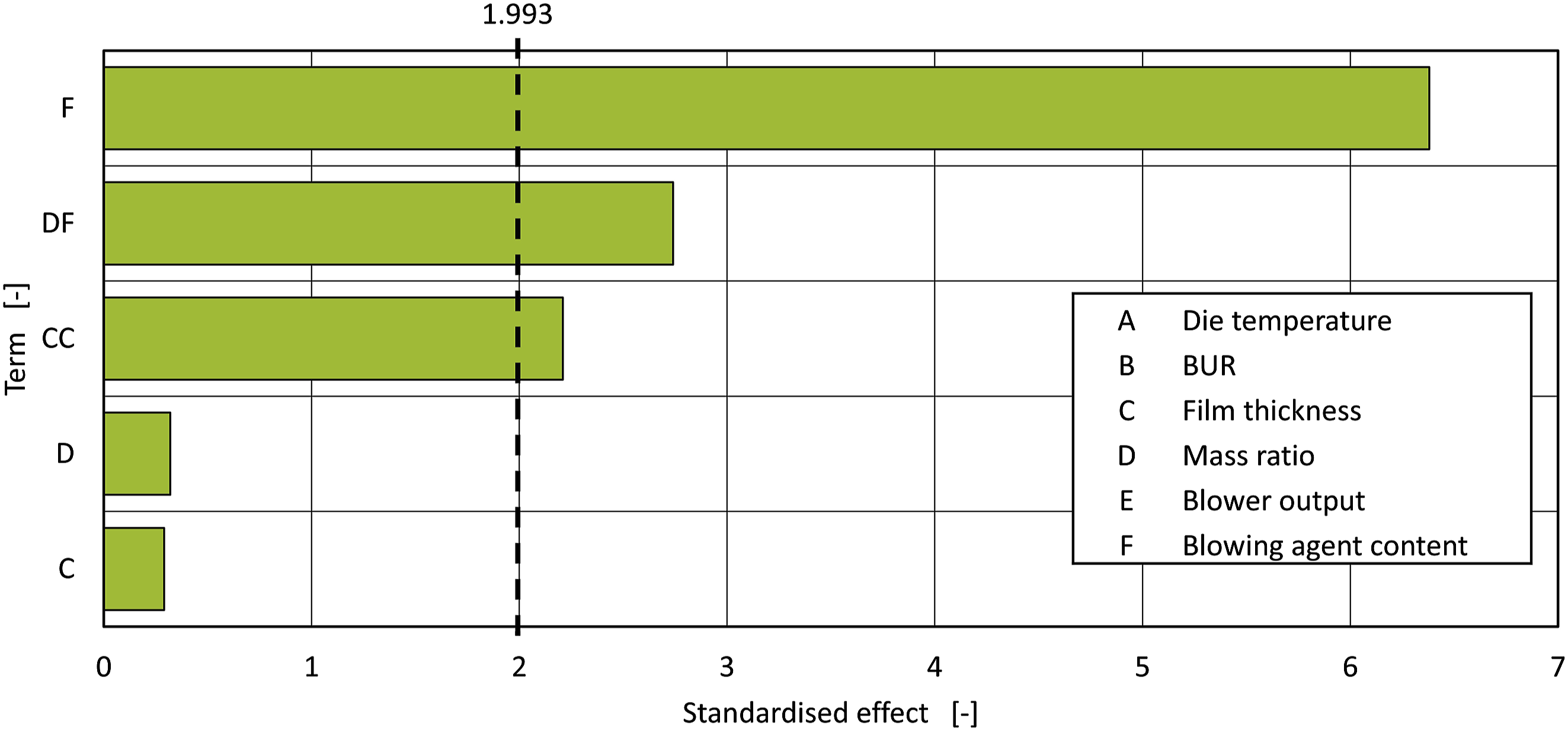
The probability network (Figure 2(a)), the residuals histogram (Figure 2(b)), the homoscedasticity (Figure 2(c)), and the autocorrelation of the residuals (Figure 2(d)) have been analysed and are fulfilled or rejected, so that the results are normally distributed, linearly deviated and not autocorrelated. The outliers (blue bordered) are two test points for which no anomalies can be detected in the parameter management of the tests. One reason for the large deviation of these test points from the model is due to process inaccuracies in the independent control of the extruder and the take-up. As a result, the film thickness varies within a test point in the control process. In addition, one test point has a very low frost line height of 60 mm, while the other test point has a very high frost line height of 320 mm above the die outlet. It can therefore be assumed that heat dissipation is sub-optimal due to the geometrically non-adapted flow of cooling air to the film. Minitab automatically corrects for these outliers when building the model. (a, b, c and d) Residual diagrams for the statistical model for the density.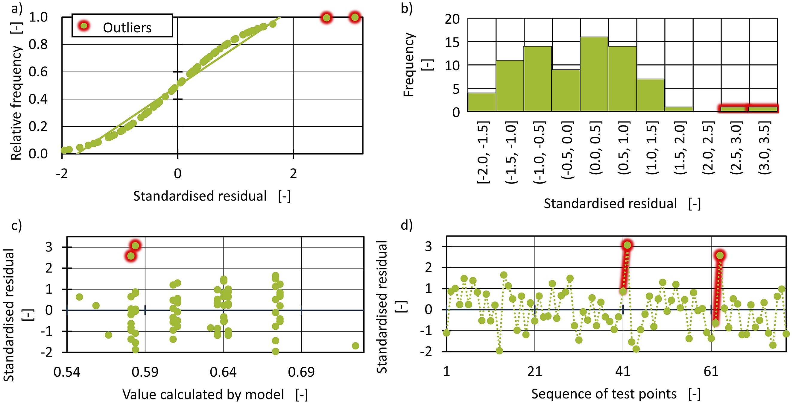
Figure 3 shows the three main effects of the factors on the density of the foamed film. Factors that are only used to calculate interactions and quadratic effects and are in themselves not statistically significant are shown as a dashed line in all factor diagrams. The expected effect of the blowing agent content is the most dominant. If there is a higher blowing agent content in the melt, more solid plastic is replaced by gas, which in turn reduces the density. Therefore, the average density decreases linearly in the factor diagram as the blowing agent increases. With a 7% blowing agent content, a 0.54 g/cm3 density can be achieved. With a 3% mass proportion, only 0.73 g/cm3 can be obtained. This effect is known for foaming and was also determined with the same type of blowing agent (hydrocerol) in a polypropylene by Behravesh et al.
30
Main effect diagram of density.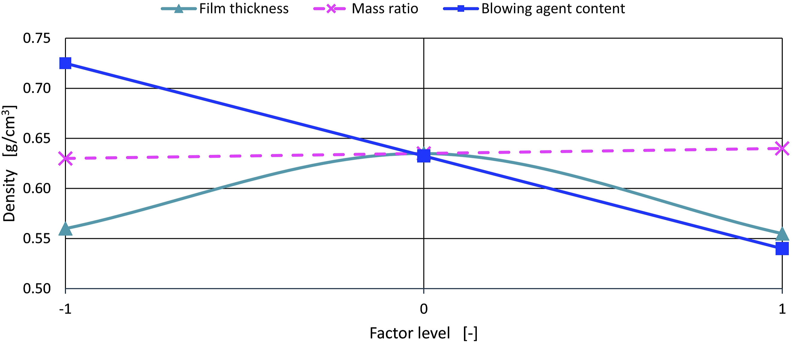
The film thickness shows a quadratic interaction (parabolic course) on the density with itself. A maximum density can therefore be recognised at 130 µm film thickness and a 0.64 g/cm3 density. The minimum density at 0.56 g/cm3 at low and very high film thicknesses, can be explained by the foaming and cooling process. Very thin films are produced at high TUR and are therefore stretched more and cool faster than thick films. Although the diffusive cell growth is stopped early by the rapid cooling, a mechanical enlargement of the cells still takes place due to the strong stretching of the cells in TD. The cells are then oval, but the foam structure is no longer fine-celled. The stretching of cells and their influence on the density and film properties was investigated in blown film extrusion by Hamdi et al.16,17 for piezoelectric films. Despite the higher density of fine-cell and unstretched cells, the required properties of the films are considerably better.16,17
Thick films in turn cool down slowly. The diffusive cell growth period is significantly longer. The result is a fully formed foam structure with large foam cells that have absorbed all the gas dissolved in the melt. The cell size is inversely proportional to density.; as already mentioned in the presentation of the parameters, this is due to the small number of cell walls in the same surface element. The density therefore reaches a minimum for large cells. 11 In order to optimally utilise this effect, average film thicknesses of around 130 µm should be avoided. This means that better mechanical properties can be achieved with both thinner and thicker films due to finer cells.
In the density analysis, an effect of changing the mass ratio was expected. As presented in the material and method section, increasing the mass ratio increases the center layer throughput. This also results in a higher proportion of blowing agent, but no density change. This is presumably due to a counteracting effect. With a higher mass throughput, the pressure gradient also increases at the same time, which ensures the formation of many fine-cellular cells and is thus accompanied by an increase in density, as previously presented. 6
The interaction diagram in Figure 4 shows the relationship between the density and the mass ratio in dependence of the blowing agent content. It shows that the mass ratio has no influence on the density with a 5% blowing agent content. However, higher and lower blowing agent contents only have a strong influence on the density at high mass ratios. If a high mass ratio is selected, the effect of the blowing agent content, which is already known from the main effect diagram, becomes even more significant. This interaction is illustrated by the effect described above. As the mass ratio increases, the mass throughput of the blowing agent-loaded layer also increases in addition to the increase in the blowing agent content. With a high blowing agent content and a high mass ratio, the effect of amplification occurs. The density decreases significantly, traceable to more blowing agent and the cells stretch more at a higher TUR. With low blowing agent content and high mass ratios, the theory of the increased pressure gradient is dominant, which leads to fine-cell foam cells with a higher density. Interaction diagram of density.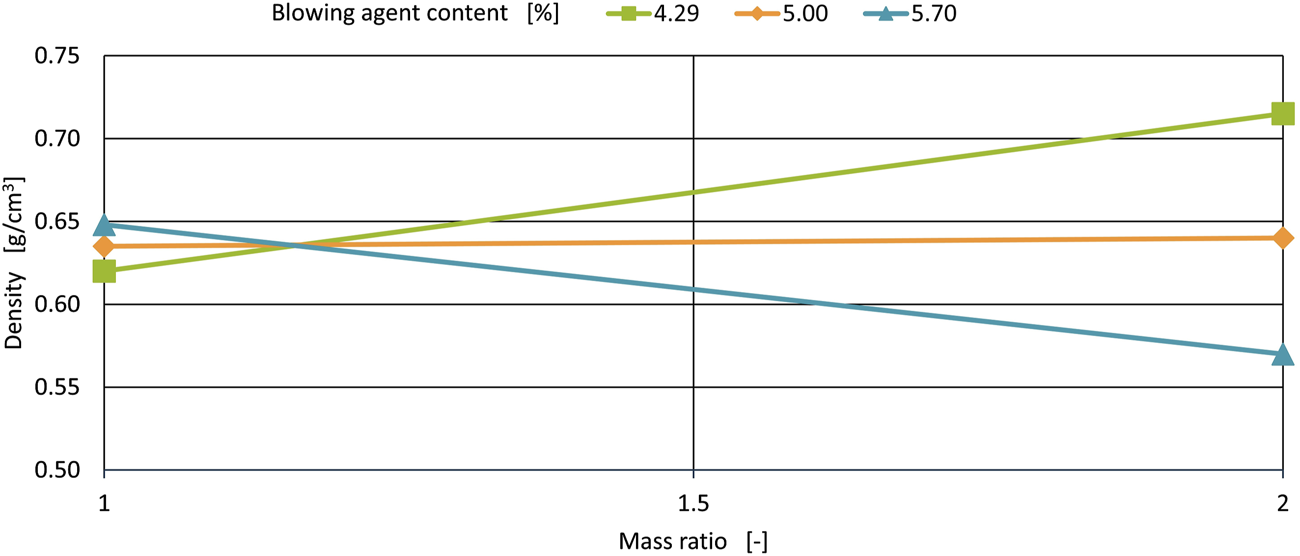
Another possible explanation for the effect of the mass ratio was analysed in more detail in the studies by Behravesh et al. 30 Here, the extruder screw speed was varied instead of the mass ratio. However, this is identical, as the throughput or the extrusion speed of the foamed layer was adjusted when the mass ratio was changed. In the studies by Behravesh et al., 30 Hydrocerol was also used as a blowing agent and its behaviour in providing gas and the resulting degree of foaming was investigated. The results show that, on the one hand, an increased screw speed introduces more shear into the material, which leads to lower melt viscosities and with this lower flow resistance there is an increased blowing agent content being released. On the other hand, an increased screw speed also reduces the probability of gas escaping through the hopper of the extrusion system due to the reduced residence time.
With regard to the interaction between mass ratio and blowing agent, these two findings can explain the effect that the mass ratio and screw speed achieve a higher degree of foaming and the associated lower density, especially with higher blowing agent content.
Mechanical properties
The film mechanical properties are among the most important key performance indicators and appear in every requirement profile and technical data sheet. The investigation of the applied orientations under various conditions is still part of the research.31,32 The Youngs-modulus represents the film stiffness and its resistance to stretching, which ensures dimensional stability during roll-to-roll processes such as printing and laminating. Additionally, it influences the bending stiffness crucial for end-use packaging. Tensile strength evaluates the film’s robustness and its capacity to withstand operational loads. Shrinkage indicates the degree of material orientation introduced during manufacturing, providing insight into other mechanical properties. The six mechanical properties can be classified according to the test direction (MD, TD).
Effects of the process conditions on the Young’s modulus of the tensile test
In the main effect diagram in Figure 5, the Young’s modulus shows the same effect behaviour for the test in both the machine and transverse direction. The elastic deformation resistance decreases with a larger film width and a higher blowing agent load, with the blowing agent content having a significantly stronger effect. With the added 7% Hydrocerol, only a 77 MPa Young’s modulus can be achieved in MD, while 106 MPa is still possible with 3% blowing agent content. The reduction in TD is from 107 MPa to 66 MPa. By adding a higher blowing agent content, the film density is reduced more. More plastic is replaced by gas. The gas has no mechanical strength or elasticity and can therefore neither absorb and conduct forces nor offer elastic resistance. Therefore, the Young’s modulus as a parameter of elastic deformation resistance decreases with higher blowing agent content. The dependence of the mechanical properties on the applied foam structure and the degree of foaming has been extensively investigated by scientists in physical foaming.33,34 (a and b) Main effect diagram of Young’s modulus.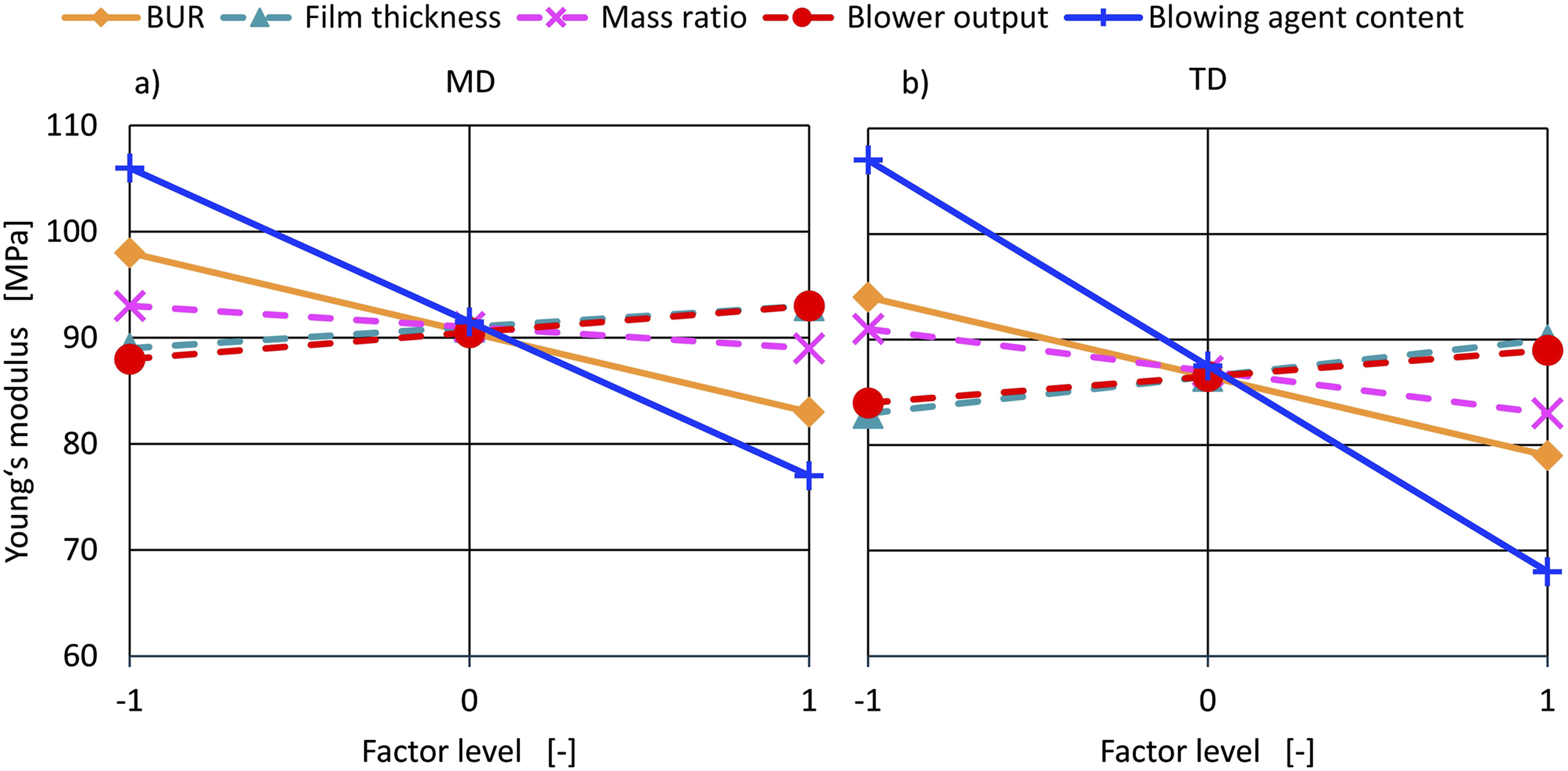
A change in the TUR or BUR is always followed by a change in the other stretching parameter.
As a result, foamed films with a larger film width have lower Young’s moduli. Compared to the TD Young’s modulus of 190 MPa, which is specified in the used LDPE data sheet, a significant reduction can be observed in the foamed film. 21
Figures 6 and 7 show the interactions effects on Young’s modulus. (a, b, c, d and e) Interaction diagram of Young’s modulus in MD. (a, b and c) Interaction diagram of Young’s modulus in TD.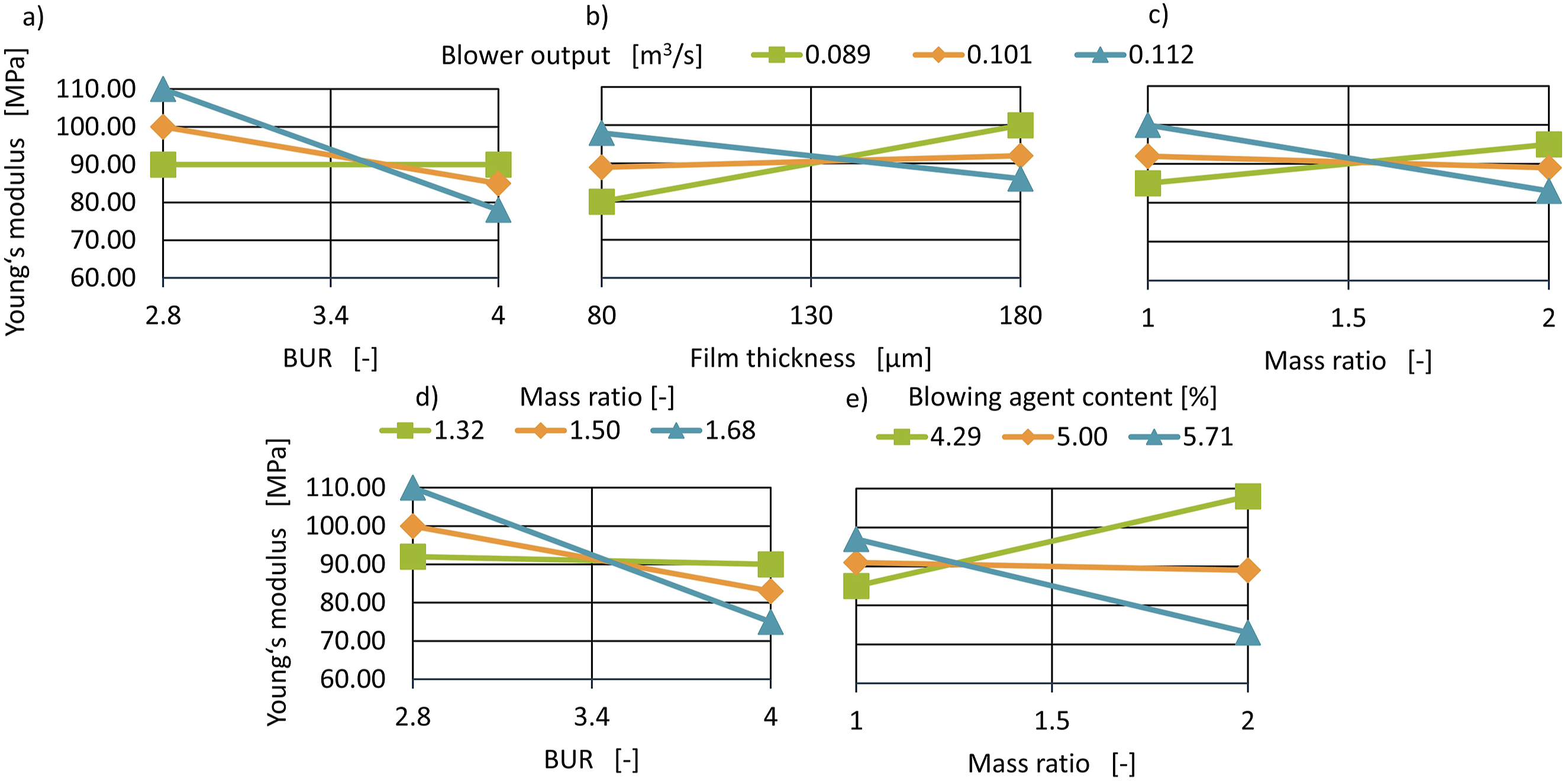
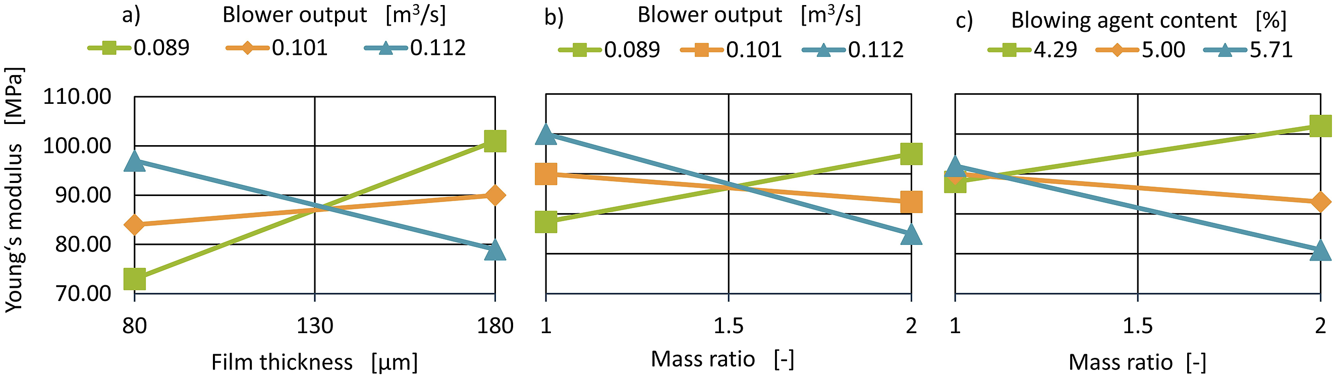
According to Figures 6(b) and (c) as well as 7(a) and (b), the Young’s modulus in both directions at an average blower output of 0.101 m3/s is hardly dependent on the film thickness and mass ratio. For large film thicknesses and mass ratios the Young’s modulus decreases at high blower output while it increases for low blower output. When the mass ratio and the film thickness are increased, the properties of the foam structure outweigh the macromolecular orientation. If this foam structure is cooled quickly by a high blower output and cell growth is thus interrupted, a resistant fine-celled foam structure does not form.
Furthermore, the blowing agent content and the mass ratio also influence both Young’s moduli (See Figure 6(e) and 7(c)). At low mass ratios, the blowing agent content has only a minor effect on the Young’s modulus, as the compact outer layers offer mechanical resistance. At higher mass ratios, the middle foam layer predominates and a high blowing agent content leads to a reduction in the Young’s modulus. For the low blowing agent content, the Young’s modulus increases. If the mass ratio is increased, the take-up must be increased to maintain a constant film thickness. This introduces orientations into the film which increase the mechanical properties. 19 In this context, the drop in Young’s modulus is even more significant with a high mass ratio and high blowing agent content.
In addition, there are two interactions with the film width and the dependant response, the MD Young’s modulus. These are dependent on the blower output and the mass ratio. According to Figure 6(a) and 6(d), both graphs show a similar curve. At a low blower output of 0.089 m3/s or a low mass ratio of 1.32, the Young’s modulus hardly changes with an increase in film width. Below a critical film width of 450 mm, the Young’s modulus increases with higher blower outputs or mass ratios. Above the critical width, the Young’s modulus decreases with a higher blower output or a higher mass ratio.
The film width/blower output interaction shows the opposite effect to the film thickness/blower output interaction. Due to the greater stretching transverse to the extrusion direction, the film is stretched less in the extrusion direction. The macromolecules are less strongly stretched in MD, and the foam structure properties, which cannot be fully formed at high blower outputs, again predominate.
The film width/mass ratio interaction is also explained by the stronger foam structure stretching. The cell wall’s macromolecules are TD orientated, which is why the MD orientation and thus the mechanical resistance decreases. This effect is more pronounced with a high mass ratio.
Effects of the process conditions on the maximum tensile stress
The maximum MD tensile strength decreased on all factors except for the blower output (see Figure 8(a)). The blown film die temperature, film width, film thickness, mass ratio and blowing agent content reduce the maximum stress absorbed from over 10 MPa to less than 9 MPa. In contrast, only the blower output increases the tension from 8.6 MPa to 10.1 MPa. According to Figure 8(b), only the blowing agent content has a statistically significant effect across the extrusion direction and reduces the maximum stress from 8.1 MPa to 5.1 MPa. It can be seen here that the stress in the extrusion direction is higher on average than in the transvers direction due to the greater film stretching. This is a well-known phenomenon in blown film and has been extensively studied by Zhang et al.,
35
Ajii et al.
36
and Chai.
37
They analysed correlations between the amorphous PS and semi-crystalline PE orientation and found that the orientations are decisive for the resulting mechanical properties.35–37 This shows that the material or the introduced foam structure has less influence and in contrast to the Young’s modulus, the film orientation outweighs the foam properties. (a and b) Main effect diagram of the maximum stress of tensile test.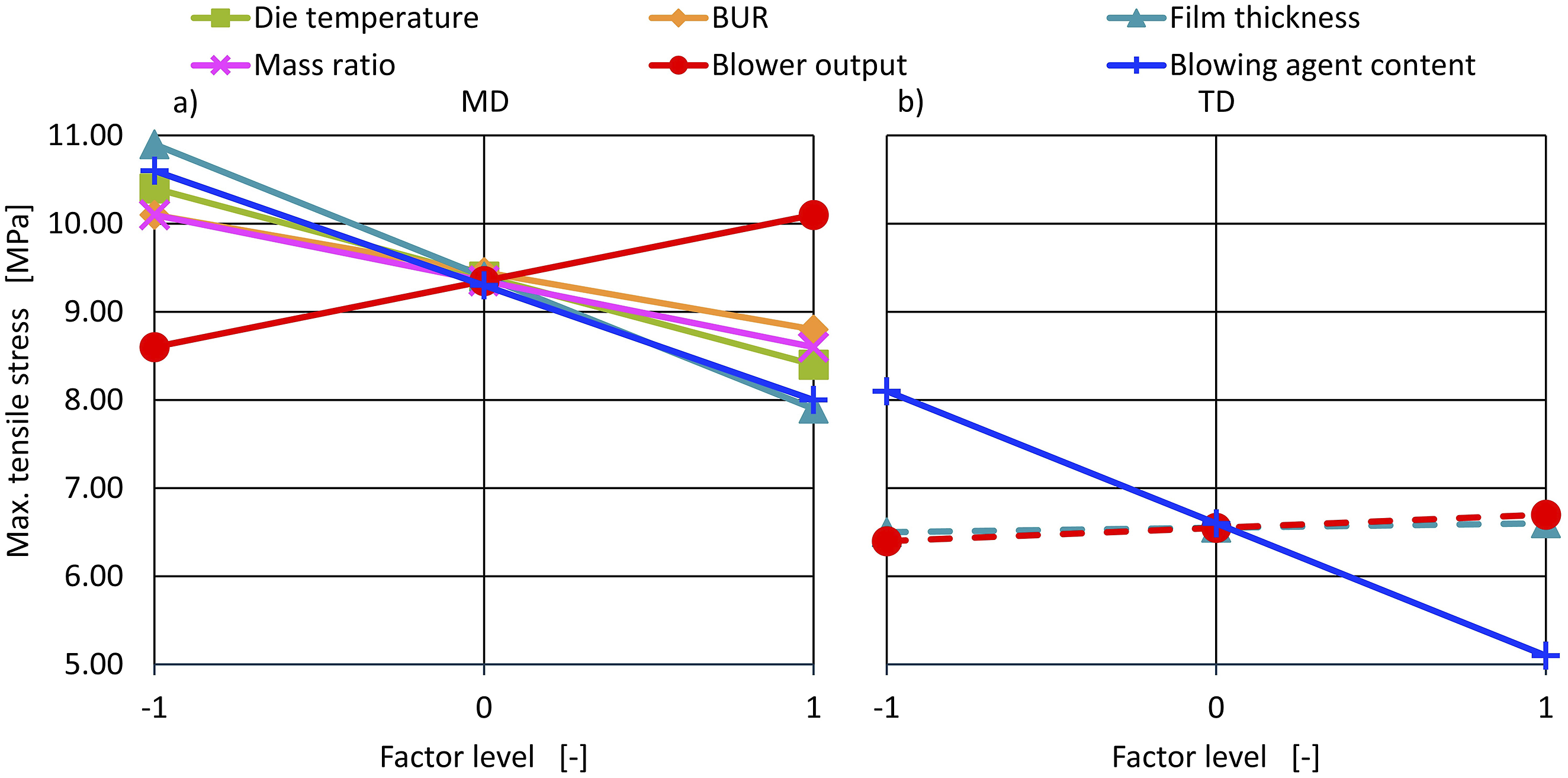
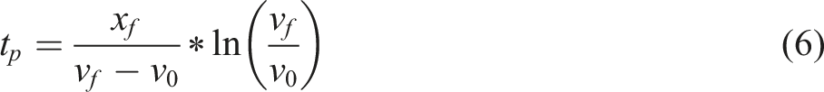
It was found that increasing the head temperature (process time from 0.1042 s to 0.3285 s) and increasing the blower power (process time from 0.2343 s to 0.0294 s) had the greatest influence, confirming the results shown. When increasing the film thickness, the change (process time from 0.1791 s to 0.1596 s) is not as significant. This is due to the increased take-up speed with thin films and the frost line moving upwards.
Take-up induced orientation can relax again before freezing. 39 The film orientation decreases and so does the tension (see shrinkage results). This can be counteracted by a higher blower output. Furthermore, the higher amount of heat contained gives the foam cells more time to grow, resulting in large cells. These also have a negative effect on the tensile strength and correlate with the density change. Here, a high film thickness resulted in a lower density, which is associated with larger cells. With a greater film thickness, the TUR is also significantly lower, which means that less orientation is introduced, leading to a lower tensile strength. 40
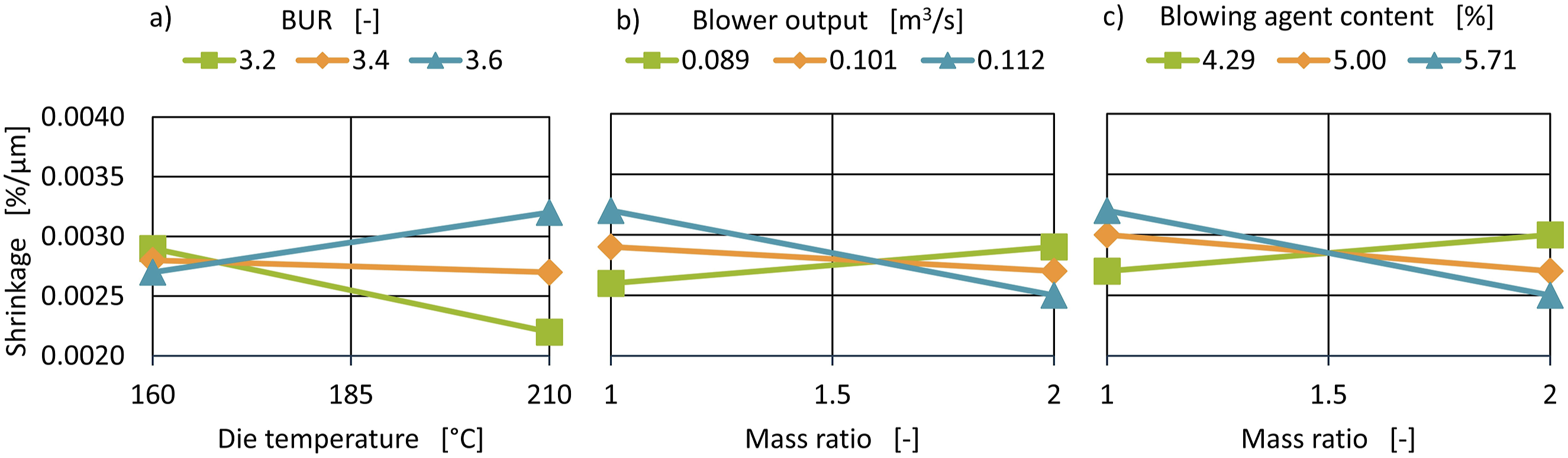
Another effect occurs when the blown film die temperature is increased. The pressure gradient determined during the extrusion tests must be taken into account. According to Hendriks et al. 41 and Park et al, 42 a high-pressure gradient, i.e. a rapid pressure reduction over time, enables a fine-cell foam structure and thus a mechanically stable foam structure. The pressure gradient depends on several factors. These include the melt viscosity, which is dependent on the melt temperature. A high melt viscosity, i.e. a low extrusion temperature, results in a high die pressure, which in turn causes a high-pressure gradient. The pressure gradient at 160°C blown film die temperature is 0.62 bar/mm and drops to 0.3 bar/mm when the temperature increases by 50 K to 210°C, thus halving. As a result, significantly fewer nucleation nuclei form, which means that a fine-cell foam structure cannot be achieved, and the mechanical properties are reduced.
Only the maximum stress in TD exhibits a single statistically significant interaction, which is shown in Figure 9. Here it can be seen that the maximum stress in TD decreases when a thick film is cooled more quickly. This effect corresponds to the main effect of the decrease in tension in the extrusion direction for thick films. However, due to the high cooling capacity, a strong orientation in the take-up direction can also be integrate in thick films. As the orientation is now in the MD, the orientation in TD decreases (see equation (5)). Interaction diagram of maximum stress of tensile test in TD.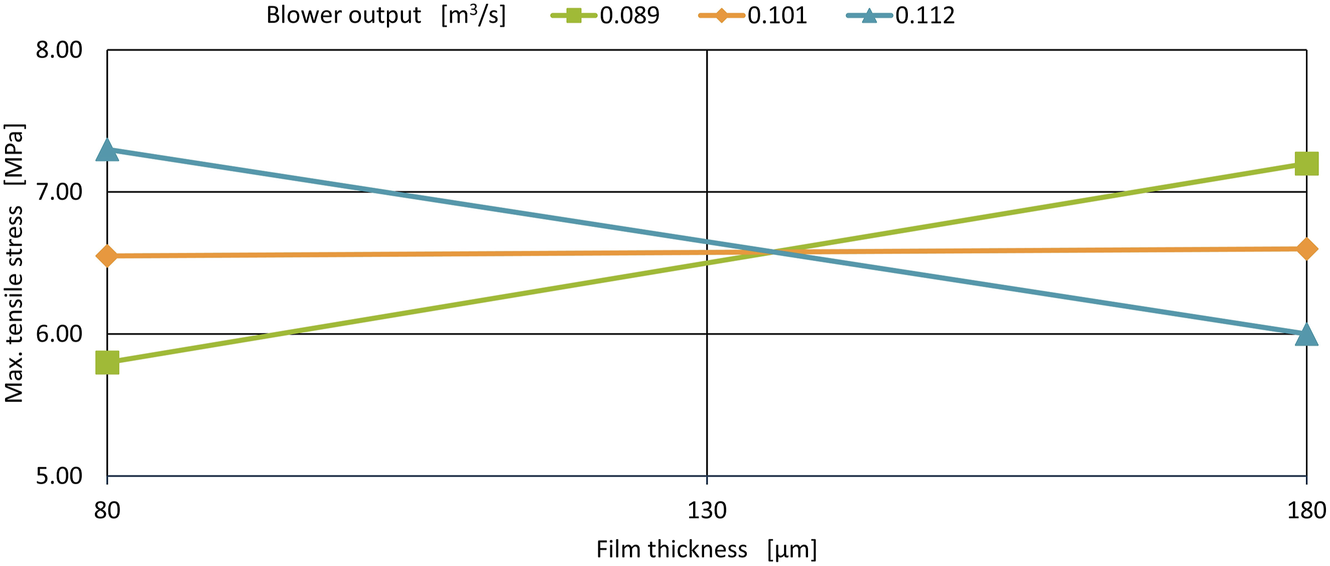
Effects of process conditions on shrinkage
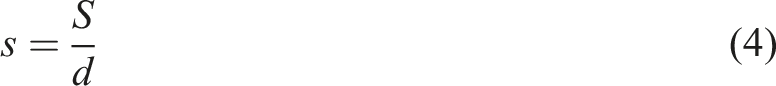
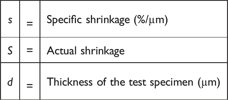
The film MD shrinkage is greater than in the TD. For example, the average specific MD shrinkage is 0.005%/µm according to Figure 10(a), while it is 0.0028%/µm in TD according to Figure 10(b). Because the shrinkage test mainly determines the degree of orientation, it can therefore be assumed that there is greater MD stretching and orientation. This confirms the correlation between mechanical strength and resistance and orientation. (a and b) Main effect diagram of shrinkage.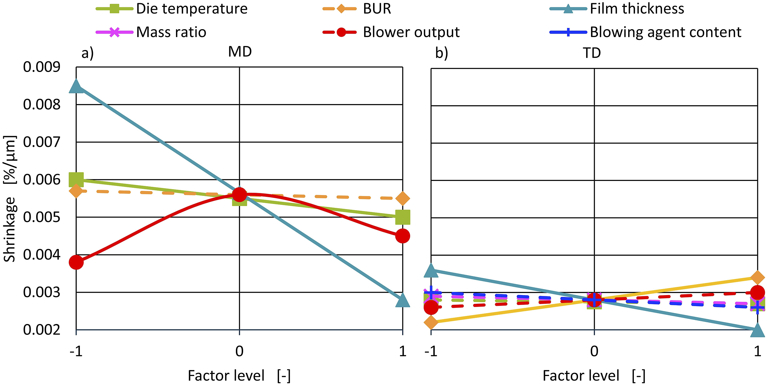
It is important to note that the blowing agent content does not have a statistically significant main effect on the shrinkage properties. The film’s orientation is independent of the foam structure. The mass ratio and the blowing agent content are only significant in the interactive effects of TD shrinkage. This effect is not expected and shows that only the introduced orientations affect shrinkage.
The film thickness and thus the take-up ratio have the largest effect on shrinkage in both directions. When the film thickness is increased from 80 µm to 180 µm, the shrinkage in MD decreases from 0.009%/µm to 0.003%/µm, and in TD from 0.0036%/µm to 0.002%/µm. In the MD, the blown film die temperature also has a negative effect on shrinkage. However, this only decreases minimally from 0.006%/µm to 0.005 %/µm. The reason for this is again the MD and TD orientation relaxation for thicker or warmer extruded films due to their longer cooling process and the lower stretching to achieve the greater film thickness. This is due to the longer process time (calculated in section Tensile strength - equation (6)).
The blower output also influences the MD shrinkage. This effect exhibits a quadratic and linear behaviour. At 0.089 m3/s, a 0.0038%/µm shrinkage occurs, while at 0.112 m3/s a 0.0045%/µm shrinkage occurs. In between is a maximum at 0.101 m3/s with a 0.0057%/µm shrinkage. The linear shrinkage increase with increasing blower output can be explained by the faster cooling, resulting in stronger, film cold stretching and orientation. This behaviour continues up to the medium blower output. Above this blower output, the shrinkage decreases again. The shrinkage should actually continue to increase. The recorded frost line height and also the calculated process time (see section Tensile strength equation (6)) confirm this behaviour. The frost line height decreases as the blower output is increased. A 270 mm frost line is present at 0.089 m3/s blower output and is reduced to 210 mm at 0.101 m3/s. With ideal air cooling at 0.112 m3/s blower output, only a 30 mm frost line is recorded. This means that the elongation takes place in less time, which leads to a higher elongation rate and should proportionally increase the shrinkage. As there are other influencing variables in the combined foamed blown film extrusion process due to the foam introduced, this behaviour may be attributable to the foam. The extremely fast cooling with a 0.0294 s process time could be due to a strongly interrupted foam formation and have a negative influence on the shrinkage. This causal relationship should be investigated in more detail.
In addition, the film width also influences the TD shrinkage. As the BUR increases, the shrinkage also increases from 0.0022 %/µm to 0.0034 %/µm. This can be explained by the stronger TD orientation at high film widths. This again leads to the properties already presented in the tensile strength chapter, which are largely determined by the applied orientation.35–37 This dependency can also be seen in the shrinkage, as it relates to the orientation. The foam structure has no major influence, as can be seen from the fact that the blowing agent content has no influence.
The two factors film width and blown film die temperature also interact with shrinkage in both directions. In the MD, Figure 11 shows only a small effect of the die temperature on the shrinkage for a 3.6 BUR. This wide film is stretched more across TD. However, a higher blown film die temperature is necessary to achieve MD orientation. The longer cooling process allows the transverse orientations to relax, and the film can be MD stretched. However, if the BUR is 2.8, its shrinkage is high at a low blown film die temperature and decreases as the temperature increases. At low BURs, the TD relaxation is no longer significant. With the higher die temperature, only the MD orientation relaxes and the shrinkage decreases. Figure 12(a) shows this effect runs in the opposite direction transverse to the extrusion direction. Interaction diagram of MD shrinkage. (a, b and c) Interaction diagram for TD shrinkage.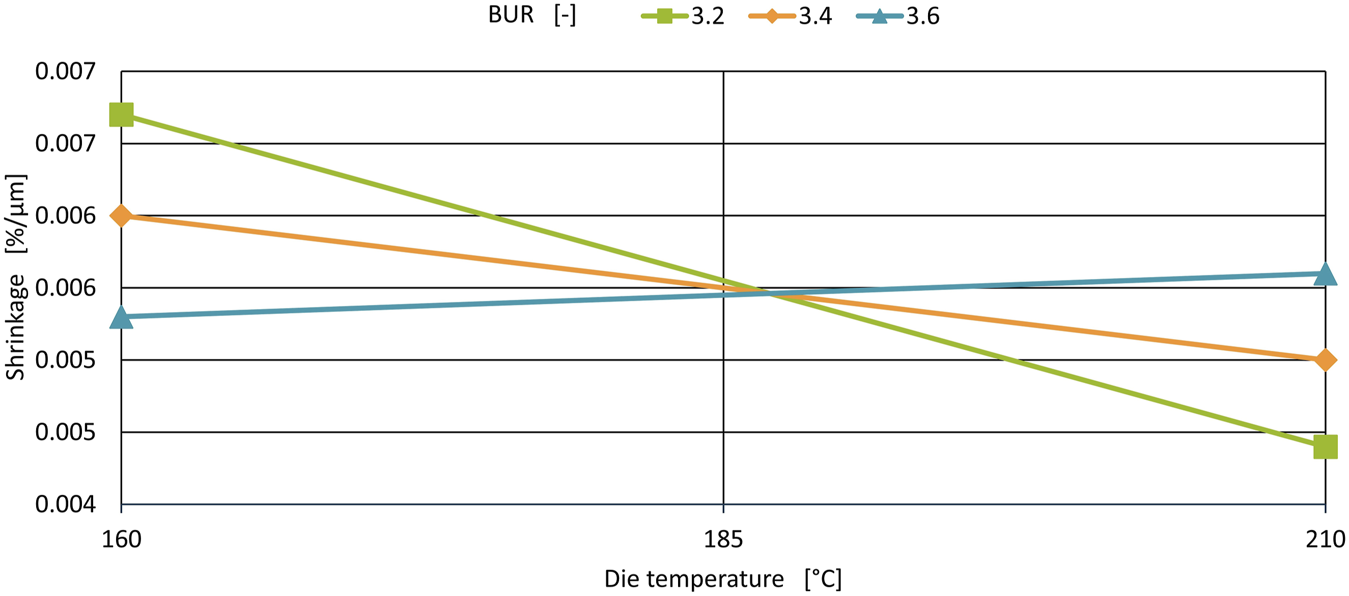
Two further interactions influence the TD shrinkage. The mass ratio (Figure 12(b) and (c)) interacts with the blower output and the blowing agent content. The blowing agent content and mass ratio interaction in Figure 12(c) again clearly shows that the foam structure has only a minor effect on shrinkage. From a 5% blowing agent content, the TD shrinkage decreases with a higher mass ratio. For less than 5% blowing agent content, the shrinkage increases slightly. The mass ratio and blower output interaction is equally slight in Figure 12(b). With a high mass ratio, a low blower output causes a higher TD shrinkage.
To summarise, the various KPIs (Density reduction, Young’s modulus, Tensile strength, Shrinkage) effects can be assessed very well. And most effects can also be traced back to the orientations introduced or the foam formation. The blowing agent content has the highest effect on the KPIs. Figure 13 shows the density and the mechanical properties in machine direction in more detail. Here it becomes clear that in the combined foamed blown film process, a trade-off must be made between density savings and mechanical properties. Figure 13 shows how much changing from 3% to 7% blowing agent makes a difference. The density drops from 0.725 g/cm3 (3%) to 0.548 g/cm3 (7%). This saves 21% or 40% compared to the raw material density. The tensile mechanical properties decrease significantly (see Figure 13). Only the shrinkage is almost independent. Summarised MD effects for 3 to 5% blowing agent content.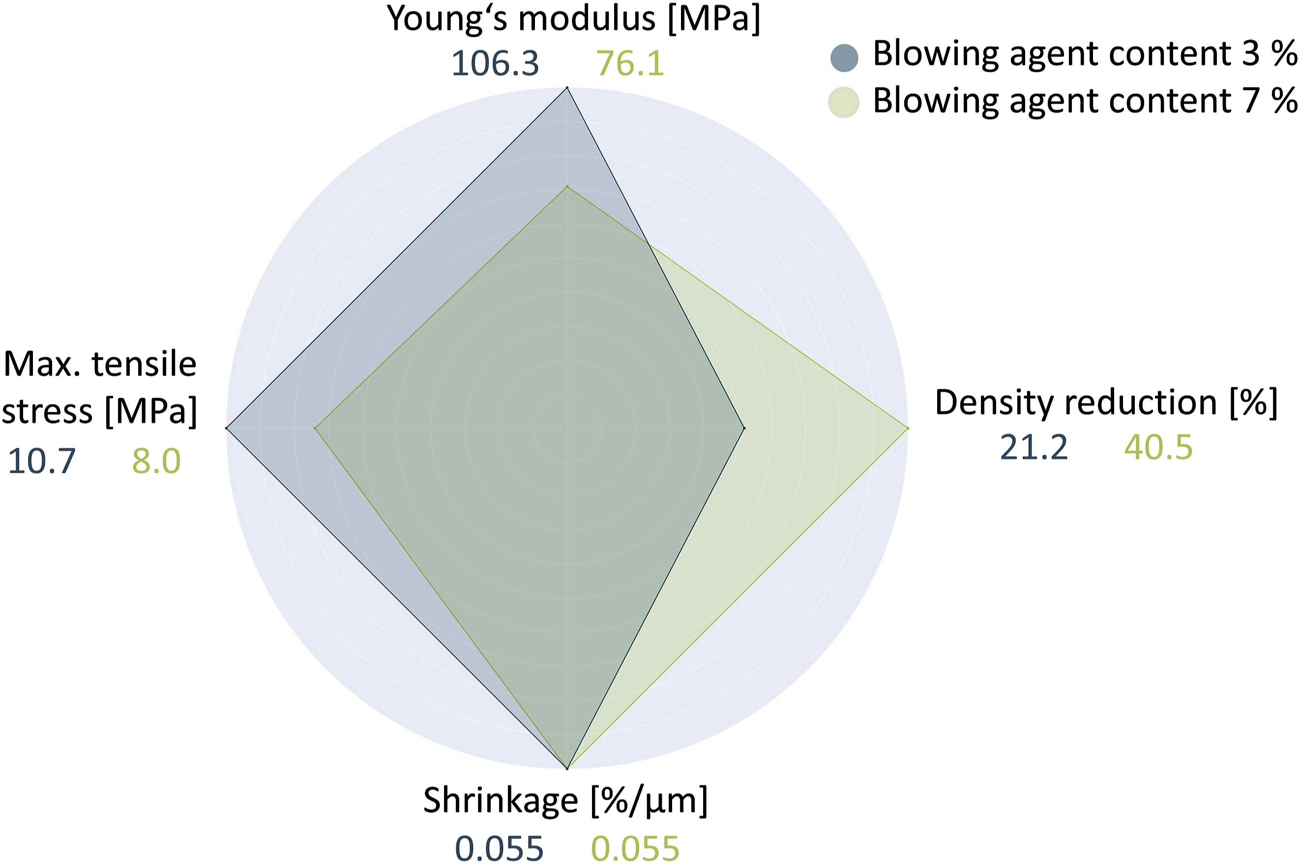
In addition to the blowing agent content, the foam cell stretching significantly determines the density and mechanical properties. This is caused by the film thickness or take-up ratio, the film width or blow-up ratio and the temperature control through blown head die temperature or blower output. This is particularly evident in the Young’s modulus.
On the other hand, orientation in the blown film process significantly improves the mechanical properties. Introducing the orientation through high TURs and BURs and the earlier freezing o through low blown film die temperatures and high blower output has a significant influence here. This process dominates the tensile strength and shrinkage achieved.
Thus, a high density saving can be achieved and a reduction in mechanical properties counteracted by targeted adjustment of the process conditions of both processes.
Conclusion and outlook
By combining blown film extrusion with foam extrusion, a high-throughput manufacturing process in the plastics industry is made more sustainable by saving raw materials. The evaluation of blown film foams aims to provide a comprehensive understanding of the process conditions that influence their mechanical properties. This includes identifying statistically significant parameters (Aim 1), analysing the interplay between orientation and foam structure (Aim 2), and optimising process parameters to achieve a sustainable production process in line with environmental and economic considerations (Aim 3).
A statistical design of experiments approach identified process parameters that significantly influence the foamed blown film mechanical properties. The blowing agent concentration determines the foam structure with a significant effect on density and mechanical properties. Film thickness (TUR), film width (BUR) and cooling rate play a key role in molecular orientation and significantly affect modulus and tensile strength. The results highlight the need to fine-tune these parameters in order to optimise the balance between strength and lightweight properties.
A key result is whether the mechanical properties are primarily determined by the molecular orientation during blown film extrusion or by the foam structure incorporated into the films. The experimental results indicate a synergistic relationship between these factors in some areas. Films with higher molecular orientation show improved tensile strength, shrinkage and Young’s modulus. These properties are mainly influenced by the film geometry (TUR, BUR) and the cooling rate during extrusion, which aligns the polymer chains and increase their load-bearing capacity. The foam structure contributes significantly to properties such as density reduction and an undesirable mechanical property reduction. The cell wall thickness, cell size and distribution play a critical role and are determined by the blowing agent content and the resulting pressure gradient. These effects can be at least partially compensated for by adjusting the other process conditions.
To achieve environmental and economic sustainability in film production, process parameters must be optimized to minimize material consumption while maintaining or improving mechanical performance. For example, the multilayer film density can be significantly reduced by combining foam and blown film extrusion. By adding 7% blowing agent, 40% plastic can be saved. Higher concentrations reduce material consumption but require careful handling to avoid excessive strength loss. Based on this study, the foam blown film extrusion process can be strategically optimized to achieve both performance and sustainability goals.
The results provide important insights into the process conditions for blown film foam extrusion. However, as this process is highly complex and is influenced by many variables, further questions arise. These include how material properties such as shear viscosity, elongation viscosity and molecular weight and its distribution influence foam formation and the general suitability for foaming.
Supplemental Material
Supplemental Material - Correlation between process conditions and mechanical film properties in foamed multilayer blown films
Supplemental Material for Correlation between process conditions and mechanical film properties in foamed multilayer blown films by Marius Stieglitz, Christian Hopmann, Lisa Leuchtenberger-Engel and Henrik Junge in Journal of Plastic Film & Sheeting.
Footnotes
Acknowledgments
The research project (18977 N) of the Forschungsvereinigung Kunststoffverarbeitung is sponsored as part of the “industrielle Gemeinschaftsforschung und -entwicklung (IGF)” by the German Bundesministerium für Wirtschaft und Energie (BMWi) due to an enactment of the German Bundestag through the AiF. We would like to extend our thanks to all organisations mentioned.
Author contributions
Marius Stieglitz, M.Sc. is leader of the working group “Blown Film Extrusion” at the Institute for Plastics Processing (IKV) at RWTH Aachen University. Prof. Dr.-Ing Christian Hopmann holds the Chair for Plastics Processing and is Head of the IKV. Lisa Leuchtenberger-Engel, M.Sc. is Head of the department Extrusion and Rubber Technology at the IKV. Henrik Junge, B.Sc., wrote his bachelor thesis at the IKV in the working group Blown Film Extrusion at the IKV.
Declaration of conflicting interests
The author(s) declared no potential conflicts of interest with respect to the research, authorship, and/or publication of this article.
Funding
The author(s) received no financial support for the research, authorship, and/or publication of this article.
Supplemental Material
Supplemental material for this article is available online.
Biographies
References
Supplementary Material
Please find the following supplemental material available below.
For Open Access articles published under a Creative Commons License, all supplemental material carries the same license as the article it is associated with.
For non-Open Access articles published, all supplemental material carries a non-exclusive license, and permission requests for re-use of supplemental material or any part of supplemental material shall be sent directly to the copyright owner as specified in the copyright notice associated with the article.