
Abstract
Post-tensioned cross-laminated timber (PT-CLT) walls coupled with U-shaped flexural plates (UFPs) have proved to be a low-damage seismic force-resisting system (SFRS) due to their self-centering capability and stable energy dissipation. Global efforts have been made to explore the applicability of PT-CLT walls as primary SFRSs in mass timber buildings. Adoption of the sixth-generation Seismic Hazard Model (SHM6) in the 2020 National Building Code of Canada resulted in a nationwide increase in seismic hazard. Given the increased popularity of mass timber buildings and the elevated seismic hazard, a comprehensive study is required to examine their performance in high seismic regions with complex seismotectonics, such as southwestern British Columbia, Canada. Therefore, this article presents the seismic design and performance evaluation of three-, six-, and nine-story mass timber buildings that use PT-CLT shear walls with coupling UFPs as SFRS for the seismicity of Vancouver, Canada. The prototype buildings were designed using the direct displacement-based design (DDBD) approach considering the SHM6. Two-dimensional fiber-based numerical models were developed in OpenSeesPy and validated with full-scale quasi-static cyclic and shaking table experimental tests. Nonlinear static and response history analyses were carried out to assess the structural responses and validate the DDBD procedure. Incremental dynamic analyses (IDA) were conducted using 80 ground motions selected for each building to develop fragilities and to estimate collapse margin ratios (CMRs). The IDA results demonstrate that all the examined buildings have adequate CMRs compared with acceptable limits in the literature. Overall, this study demonstrated that PT-CLT walls with coupling UFPs are a potential SFRS alternative in Canada’s high seismic-risk regions.
Keywords
Introduction
Mass timber buildings based on cross-laminated timber (CLT) can be constructed using either platform- or balloon-type construction methods (Karacabeyli and Lum, 2022). In both types of construction, energy dissipation in buildings primarily depends on inelastic deformation of metal connections (Chen et al., 2022; Karacabeyli and Lum, 2022; Lepine-Lacroix and Yang, 2023). Under earthquake occurrences, permanent damage to connectors could lead to problems such as permanent tilting of buildings, high repair costs, potential building demolition, and aftershock collapse (Assadi et al., 2023; Bezabeh et al., 2017; Yang et al., 2022). To enhance seismic performance and mitigate residual damage, a post-tensioned rocking wall system incorporating CLT panels (PT-CLT) and replaceable energy dissipation devices (EDDs) can be adopted to produce self-centering and ductile seismic force-resisting systems (SFRSs) (Figure 1a) that are resilient, economical, and easily constructible (Chen et al., 2020; Pei et al., 2019).
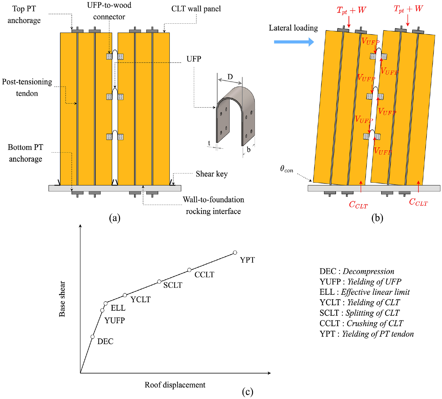
(a) PT-CLT walls coupled with UFPs. (b) System deformation and equilibrium under lateral load. (c) Base shear versus roof displacement relationship of PT-CLT walls with UFPs outlining limit states.
In a PT-CLT wall system, CLT wall panels are allowed to undergo controlled rocking instead of being rigidly fixed to the wall-to-foundation interface, whereas sliding is prevented using shear keys. Post-tensioning (PT) bars help to self-center the system by exerting a restoring moment when elongated under panel rocking. EDDs such as buckling-restrained axial fuses (BRAFs) (Rahmzadeh and Iqbal, 2018; Sarti et al., 2016; Zhu et al., 2024) and U-shaped flexural plates (UFPs) (Baird et al., 2014; Iqbal et al., 2007, 2015; Pei et al., 2019) are often used to supplement energy dissipation. With limited or negligible residual damage, such a system is economically appealing because building downtime can be significantly reduced, and post-earthquake building repairs will mainly focus on replacing the EDDs (Furley et al., 2021) as primary structural components are capacity-protected (Chen et al., 2020).
Extensive experimental testing has been conducted to investigate the structural performance of PT mass timber rocking walls. Early testing in New Zealand primarily focused on post-tensioned laminated-veneer lumber (PT-LVL) walls with EDDs (Iqbal et al., 2007; Palermo et al., 2005; Sarti et al., 2016). Due to the relative popularity and availability of CLT, recent testing in North America was mostly carried out using the PT-CLT walls. These include quasi-static reversed cyclic tests (Chen et al., 2018; Ganey et al., 2017), bi-directional cyclic test of PT-CLT wall-floor diaphragm sub-assemblies (Amer et al., 2024), and full-scale shaking table tests of 2-story (Barbosa et al., 2021; Pei et al., 2019) and 10-story PT-CLT shear wall buildings (Pei et al., 2023). Based on experimental observations from two shaking table tests, Wichman (2023) recommended 1%, 2%, and 3% inter-story drift ratios (ISDRs) corresponding to seismic performance objectives (POs) of immediate occupancy (IO), limited repair (LR), and collapse prevention (CP).
Several studies have assessed the seismic performance of post-tensioned mass timber rocking walls using numerical approaches (e.g. Akbas, 2016; Kovacs and Wiebe, 2019; Sarti et al., 2017; Furley et al., 2021; Ho et al., 2023; Wilson et al., 2020). Akbas (2016) developed 6- and 11-story prototype buildings equipped with PT-CLT walls with coupling UFPs and examined their performance under a design basis earthquake (DBE) (10% in 50 years) and a maximum credible earthquake (MCE) (2% in 50 years). Although the investigation concluded satisfactory performance of the prototype buildings, the exceedance probabilities of POs were not evaluated. Following the FEMA P695 approach (FEMA, 2009), Sarti et al. (2017) determined seismic performance factors for PT-LVL walls. Kovacs and Wiebe (2019) conducted a collapse assessment for three-, six-, and nine-story buildings with PT-CLT walls without EDDs for Montreal, a city of moderate seismicity in Canada, and reported that the probability of collapse under MCE ground motions is less than 10%. Wilson et al. (2020) applied performance-based seismic design for a 5-story office building and a 12-story residential building with PT-CLT wall coupled with UFPs as SFRS. Nonlinear response history analyses (NLRHA) concluded that both buildings met the ISDR limit specified in ASCE 7-16 (ASCE, 2016) and that structural damage was limited to crushing at the CLT wall toe and UFP plastic deformation. Ho et al. (2023) evaluated the seismic performance factors of a three-story post-tensioned mass plywood panels (PT-MPP) rocking wall with coupling UFPs and developed limit-state-dependent fragility functions based on truncated incremental dynamic analysis (IDA) using ground motion set from FEMA P695 (FEMA, 2009). However, the study was limited to a single three-story building.
In Canada, adoption of the sixth-generation Seismic Hazard Model (SHM6) (Kolaj et al., 2020) by NBCC 2020 (National Research Council of Canada (NRCC), 2020) resulted in a nationwide increase in seismic hazard. In addition, Canada has regions with complex seismotectonics, such as Southwestern BC, where three different damaging sources of earthquakes coexist: the shallow crustal, deep in-slab, and interface (Goda, 2019). As a result, seismic design and performance of buildings are anticipated to be greatly impacted (Odikamnoro et al., 2022; Popovski et al., 2021). To further validate the applicability of PT-CLT walls in high seismic-risk zones of Canada, this article assessed the seismic performance of three-, six-, and nine-story PT-CLT shear wall buildings with UFPs, considering diverse earthquake types and increased seismic hazards in southwestern British Columbia (BC), Canada. The performance evaluation considered various POs and used nonlinear static and dynamic analyses.
This article is organized as follows. First, the lateral behavior of PT-CLT walls is illustrated. Second, the design of the prototype buildings is presented, which was based on the direct displacement-based design (DDBD) approach. Next, a fiber-based numerical modeling strategy for PT-CLT walls with UFPs in OpenSeesPy and its validation with full-scale quasi-static cyclic and shaking table experimental tests are presented. Nonlinear static analyses (NLSA) and NLRHA are then carried out to assess the structural responses and validate the DDBD procedure. Finally, to develop the buildings’ fragilities and estimate collapse margin ratios (CMRs), IDA was conducted for each prototype building using 80 ground motion records, which were selected considering the complex seismotectonics in Southwestern BC, following SHM6 and NBCC 2020.
Lateral behavior of PT-CLT walls
The lateral response of PT-CLT walls has been studied extensively in recent years. For the sake of brevity, only a brief description is provided in this section; therefore, for more details, we direct readers to earlier work (Akbas et al., 2017; Chen et al., 2018; Ganey et al., 2017; Pei et al., 2019; Wichman, 2023; Zhu et al., 2024). In PT-CLT walls, the overturning moment due to lateral loading is initially resisted by gravity load and initial PT force until decompression (DEC), before which the wall exhibits exclusively elastic deformation due to flexure and shear. As the DEC is exceeded, rigid body rocking of the panel commences. The base uplift or gap opening at one side of the CLT wall will accumulate compressive stress on the opposite side (Figure 1b). However, the initial geometric and material nonlinearity is limited, and the wall still behaves quasi-elastically until the effective linear limit (ELL). Meanwhile, EDDs could yield and start dissipating energy depending on their relative position to the rocking interface. As the contact length further reduces, CLT yielding (YCLT) can occur at the compressive toe of the wall, followed by the splitting (SCLT), crushing of CLT (CCLT) (Figure 1c). Upon the removal of lateral loading, PT bars exert a restoring moment due to its elongation, thus attaining self-centering.
In coupled PT-CLT walls, UFPs serve as coupling links and offer energy dissipation in the event of relative vertical movement between adjacent wall panels. Bending a piece of mild steel plate of a certain thickness (t) about a certain diameter (D) can produce a UFP with a semicircle and two equal side plates (Figure 1a). The side plates of UFPs can be connected to CLT walls to create coupling. The connection can be either bolted saddle connections for simple post-earthquake replacement of damaged UFPs or metal inert gas welding. Iqbal et al. (2015) conducted component-level testing for three UFPs under reversed cyclic loading. A 5-mm thickness and a 15-mm radius of curvature were chosen for all UFPs, with widths of 50, 65, and 100 mm, respectively. The experiment revealed that UFP hysteresis remained stable without distinct stiffness and strength degradation.
Seismic design of prototype PT-CLT shear wall buildings
Three-, six-, and nine-story prototype buildings, hypothetically located in Vancouver, a metropolitan city in Southwestern BC, Canada, are considered in this study. Currently, PT-CLT walls can be designed only as an alternative solution in Canada due to the absence of system-specific seismic force modification factors (
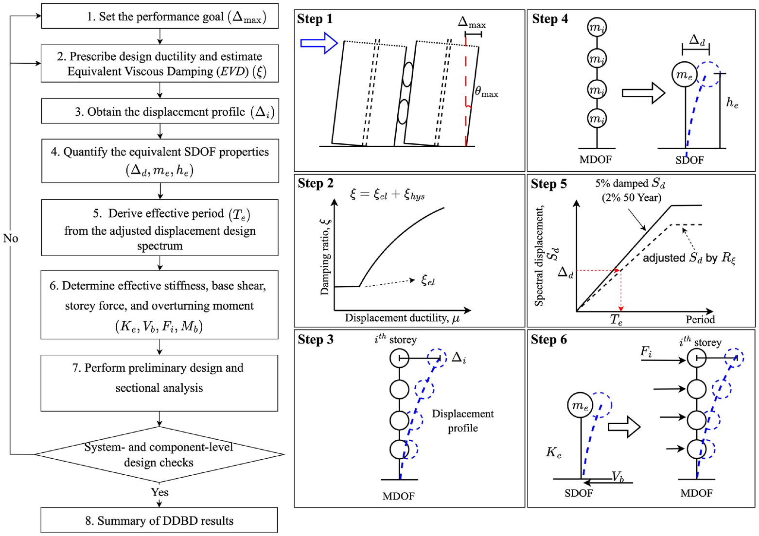
DDBD procedure for PT-CLT walls with UFPs.
In Step 1, the architectural design was first performed. All prototype buildings have a floor area of 616 m2 (Figure 3), with a ground floor height of 4 m and a typical story height of 3 m. The buildings are designated as office buildings and are situated on Site Class C soil. The floors consist of 175 mm (5-ply) CLT panels with 38 mm concrete topping. Each floor bears 3.44 kPa dead load (self-weight included) and 1.9 kPa live load, and the roof supports 1.76 kPa dead load and 1.64 kPa snow load. As shown in Figure 3, each building has four PT-CLT coupled walls in each lateral direction, resulting in eight CLT panels; 5- or 7-ply E1 grade CLT panels with an individual panel width of 3 m were adopted due to typical manufacturing capability and transportation limitations. A roof drift ratio of 2% was prescribed as the performance criterion for PT-CLT shear wall buildings under MCE events (Sarti, 2015). The 2.5% ISDR limit, as required in NBCC 2020, must also be satisfied.
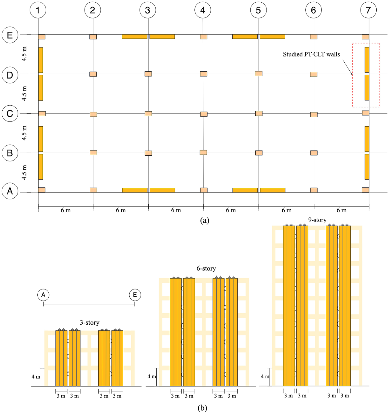
(a) Typical floor plan. (b) Schematics of three-, six-, and nine-story prototype buildings.
In Step 2, system ductility
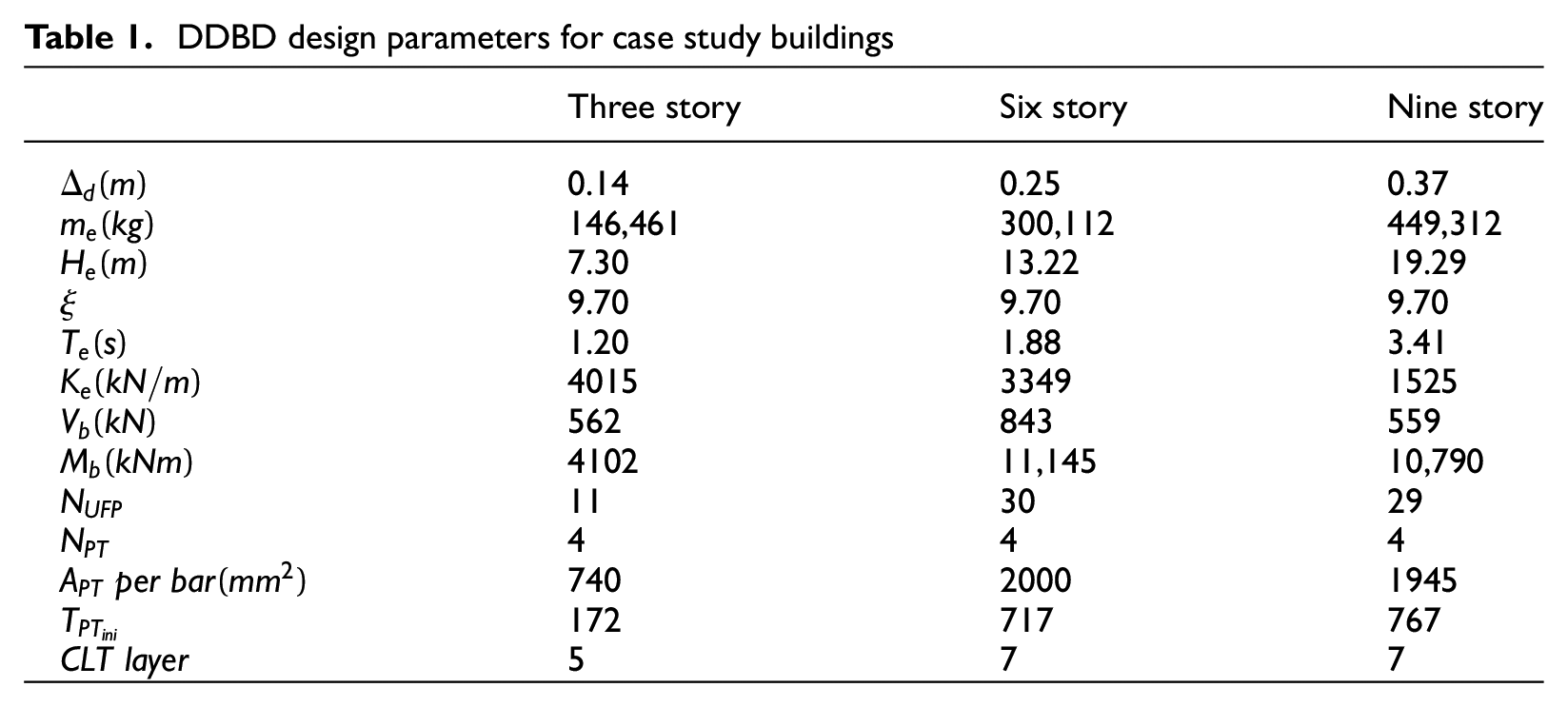
DDBD design parameters for case study buildings
Additional connection design was also performed. The lateral rocking wall can be connected to the mass timber gravity frame using shear keys inserted into a vertically slotted hole as outlined in Pei et al. (2019) to decouple the uplift of the CLT panel and the horizontal translation of the diaphragm. For six- and nine-story buildings, PT-CLT walls require multiple CLT panels, and they can be vertically stacked using embedded epoxy rod splice connections to act as a continuous element (Zimmerman and McDonnell, 2018). Such connections were subject to multiple design checks, for instance, those outlined in Wichman (2023). Furthermore, UFP-to-wall connection design was performed according to the EXPAN Design Guide (Pampanin et al., 2013).
Development of fiber-based numerical models for PT-CLT walls
For performance assessment, two-dimensional (2D) numerical models for PT-CLT walls with UFPs were developed in OpenSeesPy (Zhu et al., 2018; Figure 4). The key modeling strategies are illustrated in the following section, including component-level calibration and model validation at system and building levels.
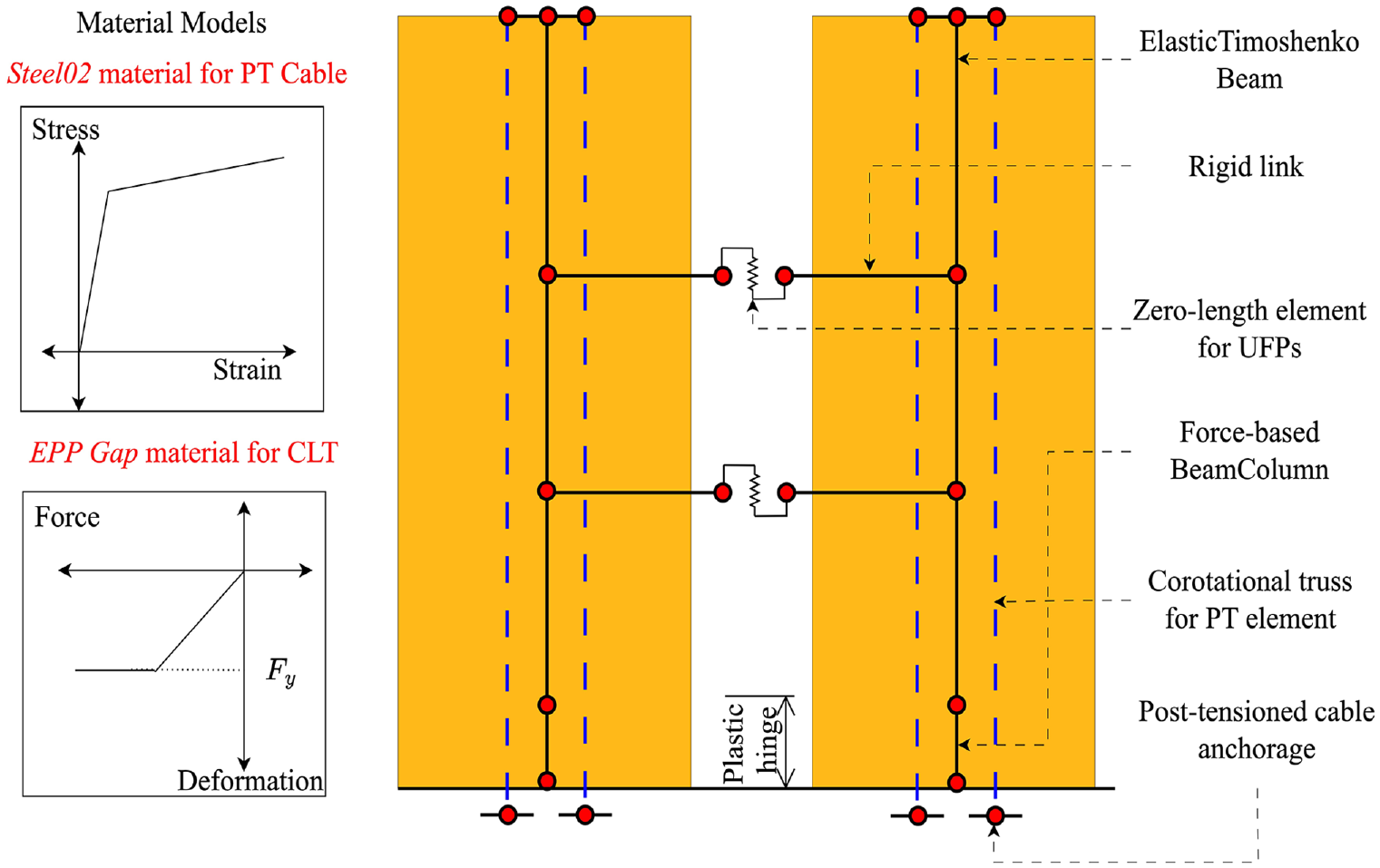
Fiber-based numerical model in OpenSeesPy.
Modeling strategy
Force-based beam-column elements with fiber sections were used to capture the deformation at the plastic zone of the CLT panel, in which the plastic hinge length is twice the wall panel thickness (Akbas et al., 2017; Figure 4). Each section was discretized to vertically oriented fibers across the length of the wall. Elastic Perfectly Plastic Gap (EPPGap) material with no tensile strength was assigned to fibers to idealize the stress and strain relationship of the CLT based on experimental observation (Chen et al., 2018) and to simulate the base uplift. The portion above the plastic hinge zone was assumed to be linearly elastic and modeled by the ElasticTimoshenko beam. The PT elements were modeled by corotational trusses assigned with the Giuffré-Menegotto-Pinto (Steel02) material. The top of the PT tendon was connected to the upper portion of the CLT panel using rigid beam elements. The initial stress function of the material was used and iteratively adjusted to attain the target initial PT force after wall precompression (Kovac and Wiebe, 2019; Slotboom, 2020). It is assumed that CLT walls have negligible compression due to the prestressing of PT elements and that the lateral load between two wall panels was transferred using a rigid link element. Zero-length elements with calibrated uniaxial material properties in the vertical direction were used to model UFPs. At each UFP location, the zero-length elements were rigidly connected to the nodes at CLT walls at the same height to account for the offset between the CLT wall and the UFPs (Akbas, 2016; Sarti, 2015; Wichman et al., 2022).
Component-level calibration for the UFPs
The Steel02 uniaxial material coupled with low-cycle fatigue material was adopted to model the UFPs (Sarti, 2015) and was calibrated using UFP experimental testing reported in Iqbal et al. (2015). The calibrated and experimental hysteresis are depicted in Figure 5, which shows good agreement for the three tested UFPs.
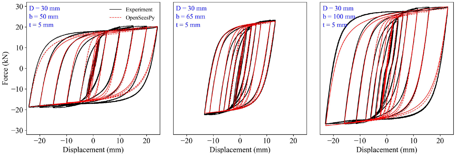
Comparison between UFP cyclic responses of numerical model and experiments.
System-level validation
The fiber-based numerical model was validated with full-scale quasi-static experimental tests conducted at FPInnovations (Chen et al., 2020; Figure 6a). The dimensions of the tested CLT panels were 1 m long, 0.143 m thick, and 3 m tall. The loading was exerted at an actuator height of 2.9 m. A single post-tensioned cable with a diameter of 20 mm was used. The initial PT force was 89 kN. Figure 6b shows the base shear force versus the horizontal displacement at the top of the CLT wall panel from the experiment and numerical simulation. A good agreement was observed between the two curves in terms of initial stiffness, post-yielding stiffness, unloading stiffness, and peak restoring force. The difference in cumulative energy dissipation between the experimental and numerical analyses was less than 0.6%. The peak roof horizontal displacement reached 75 mm without structural failure or strength degradation.
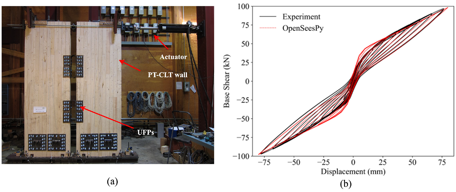
(a) Experimental testing setup (picture courtesy of Zhiyong Chen from FPInnovations). (b) Comparison between the OpenSeesPy model results and the cyclic responses from the experimental test.
Building-level validation based on shaking table tests
Building-level validation was also performed to verify the robustness of the fiber-based numerical model under dynamic loading. The target was the NHERI shaking table test of a two-story mass timber building (Pei et al., 2019), which consisted of two coupledPT-CLT walls with UFPs in the same shaking direction. The tested structure has a first and second story height of 3.66 and 3.05 m, respectively. The estimated seismic weight, excluding the weight of the CLT walls, was 391 kN for the floors and 400 kN for the roof (Wichman et al., 2022). For each coupled walls, five UFPs were employed as dissipative coupling links. Each CLT panel has four post-tensioned tendons symmetric about the centerline, with each initial PT force of 53 kN, nearly 40% of the yield force. The building was tested under 14 ground motions, including 4 ground motions scaled to three hazard intensity levels, namely service level earthquake (SLE) (50% in 30 years), a DBE (10% in 50 years), and an MCE (2% in 50 years). The detailed descriptions of the building, materials, and ground motions can be found elsewhere (Barbosa et al., 2021; Pei et al., 2019; Wichman, 2018; Wichman et al., 2022).
A 2D numerical model (Figure 7) was developed for one of the two walls because the structure is symmetric, and negligible torsion was observed during the experiment (Wichman et al., 2022). It is assumed that each individual panel resists a quarter of the overall seismic force for the rigid diaphragm (Pei et al., 2019), and the corresponding seismic mass was defined at the floor nodes on CLT walls. An additional gravity-leaning column representing the gravity system was defined in OpenSeesPy to capture potentialP-Delta effects. The leaning column was modeled with elastic beam–column elements and was pinned at the foundation (Figure 7). Each floor node on the leaning column was rigidly connected to the floor node on the CLT wall. Zero-length elements with negligible rotational stiffness were defined at the junction of the floor node and its adjacent elastic columns to simulate moment release. To represent the diaphragm-to-wall connection, zero-length elements with material property assigned in the horizontal translational degree of freedom only were adopted. The material is based on the shear key dimensions and properties reported in Wichman et al. (2022). The PT-CLT wall panels were positioned on a steel foundation beam to achieve a rigid foundation. However, significant flexible foundation effects were observed during the shaking table test, impacting the overall structural dynamics (Wichman et al., 2022). Therefore, while adopting the same fiber-based modeling strategy, additional considerations proposed by Slotboom (2020) were followed to account for the foundation’s flexibility. This includes the definition of extra nodes (W1 and W2) below the bottom node at the CLT wall panels (W3). A rigid link element connecting W1 and W2 was employed to physically model the foundation beam, and a zero-length section element was used to connect W2 and W3 to capture the flexible deformation of the beam (Figure 7).
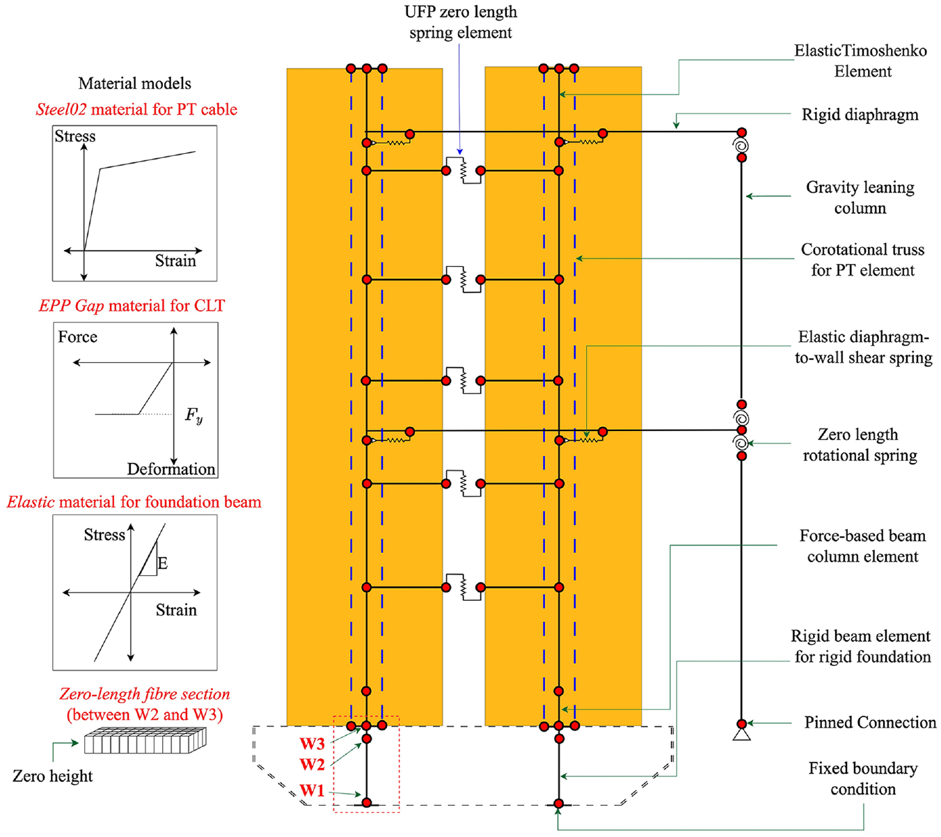
Fiber-based numerical model with flexible foundation.
Eigen-analysis was first performed to obtain the period of the system. The fundamental period of the OpenSeesPy numerical model is 0.84 s and is considered acceptable compared with the actual period range (0.73–0.98 s) based on in-situ white noise analysis (Wichman, 2018). The free vibration analysis yielded an average damping coefficient of 1.92%. Hence, 2% mass and tangent stiffness-proportional Rayleigh damping was applied in subsequent analysis, similar to the setting considered in Slotboom (2020). NLRHA was conducted for all 14 ground motions non-sequentially, and the results were compared with the raw time histories of structural responses from the shaking table test. Time histories of the roof drift ratio from three ground motions were presented and compared with the shaking table test, as shown in Figure 8. Figure 8 indicates that the model predicted displacement demands in terms of pattern and peak values with accuracy, especially under SLE events. Slight underpredictions for both responses at DBE and MCE levels are observed, similar to those observed in Wichman et al. (2022). The error in predicting the peak response is 3.6% for the DBE event and 18.4% for the MCE event, respectively. Given that the system endured all ground motions during the shaking table test, it is possible that cumulative damage in the CLT walls and PT occurred but was overlooked by the numerical model, potentially resulting in the observed underestimation.
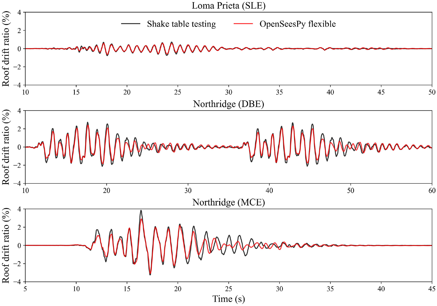
Comparison of the time history of roof drift between OpenSeesPy flexible foundation model and the shaking table test.
Seismic performance assessment
This section presents a seismic performance evaluation of the prototype buildings designed in the preceding sections by employing validated numerical models. Eigen-analysis was first conducted to quantify the prototype buildings’ fundamental periods, which are 0.35, 0.78, and 1.31 s for the three-, six-, and nine-story buildings, respectively. Sarti et al. (2017) reported that the period for PT-LVL walls can be well predicted using the empirical equation for moment-resisting concrete frames up to 1.5 s. However, for structures with longer periods, the equation tends to result in underestimations. Using the corresponding equation from NBCC 2020, the predicted periods are 0.42, 0.68, and 0.91 s. Although slight period differences were observed for three- and six-story buildings, the expected underestimation for taller PT-CLT walls was noted. Given that the empirical equation in the NBCC 2020 was specifically calibrated for concrete structures, the observed discrepancy may also stem from the inherently lower lateral stiffness and lightweight characteristics of mass timber buildings, which become increasingly significant as the height of the structure increases.
Nonlinear static analysis
NLSA was performed for each of the prototype buildings with story forces determined from the DDBD procedure. Sarti et al. (2017) concluded a 5% roof drift ratio as the maximum drift capacity of mass timber gravity frames. Pei et al. (2019) also reported that gravity connection details can withstand an ISDR of up to 5% without compromising stability or causing damages. Hence, each building was monotonically pushed using a displacement–control integrator until a 5% of the roof drift ratio (a non-simulated collapse mechanism). To consider the impact of CLT crushing and the large tensile strain of PT, simulated collapse mechanisms were included through material strain limits for both CLT and PT elements. Using the MinMax material model in OpenSeesPy, it was possible to incorporate material strain limits. When these limits are exceeded, zero tangent and stiffness are returned, accelerating building collapse. Similar practices can be found in Sarti et al. (2017), in which 1% ultimate compressive strain for LVL was assumed and implemented using the MinMax material. Kovac and Wiebe (2019) used a multi-spring modeling approach and removed the individual CLT spring element when twice the yield strain was reached, and Ho et al. (2023) incorporated MinMax material into their numerical model to consider the limit states of MPP walls. Inherent conservatism should be recognized since residual strength for CLT and PT elements remains even when the considered limit has been reached (Chen et al., 2018; Ganey et al., 2017). It is expected that CCLT precedes YPT, in which the system’s strength degradation is governed by the CCLT.
Two pushover curves are presented in Figure 9 for each prototype building. These curves correspond to models with material strain limits for CLT and PT (broken line) and without such limits (solid line). With the inclusion of the MinMax material, strength degradation was observed upon reaching the CLT crushing strain at the extreme fiber under compression and NLSA was terminated due to numerical instability. The pushover curves without MinMax material show a typical bilinear characteristic of PT-CLT walls (i.e. before and after ELL). These curves attested that the system maintains sufficient strength even after reaching the material strain limits compared with the conservatism when including the MinMax material. The figures also incorporated a series of component limit states. The stress–strain relationship of each CLT fiber was monitored, and the first onsets of CLT yielding, splitting, and crushing were identified. The CLT yielding strain was based on the value reported by Chen et al. (2018), and the splitting and crushing strains were taken as 0.02 and 0.05, respectively (Akbas et al., 2017). Figure 9 indicates that CCLT occurred at 3% roof drift for three- and six-story and 2.4% for nine-story buildings. Since the DDBD approach considered 2% roof drift as the design target under the MCE event, satisfactory structural performance of the prototype building can be demonstrated as damages due to CLT crushing can be effectively limited.
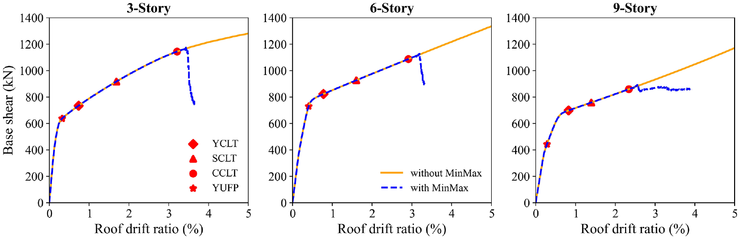
Nonlinear static analysis results for the three analyzed buildings.
Nonlinear response history analysis under MCE
To validate the DDBD procedure and evaluate the seismic performance of the prototype buildings, NLRHA was conducted. For this purpose, suites of site-specific ground motions consisting of 11 records for each earthquake type scaled to Vancouver’s UHS as defined in (NRCC, 2020) were used (Zhu et al., 2024). To perform NLRHA, a transient analysis solver was configured in OpenSeesPy. The solver included a tangent stiffness-proportional Rayleigh damping with 3% critical damping ratio. Such critical damping level was consistent with observations from past studies of post-tensioned rocking timber systems (Marriott, 2009; Pino et al. 2010; Sarti, 2015; Smith, 2014; Smith et al., 2012). Structural responses (i.e. story displacement normalized by building height and the story shear force) were extracted from each individual NLRHA. The design story shear forces from DDBD were amplified to a linear shear force envelope to account for higher mode effects (Priestley et al., 2007; Sarti, 2015; Zhu et al., 2024). Figure 10 presents the ISDR response for all prototype buildings. The performance is satisfactory because both the mean and 84% quantile responses for all buildings are lower than the 2.5% ISDR limit prescribed in NBCC 2020, with only one out of 33 ground motions causing exceedance of this limit for each of the six- and nine-story buildings. Figure 11 shows that the design shear envelope bounded the individual and median shear force responses well at each story. Overall, the adopted DDBD procedure is considered adequate to ensure acceptable seismic performance of PT-CLT shear wall buildings subjected to MCE-level ground motions.
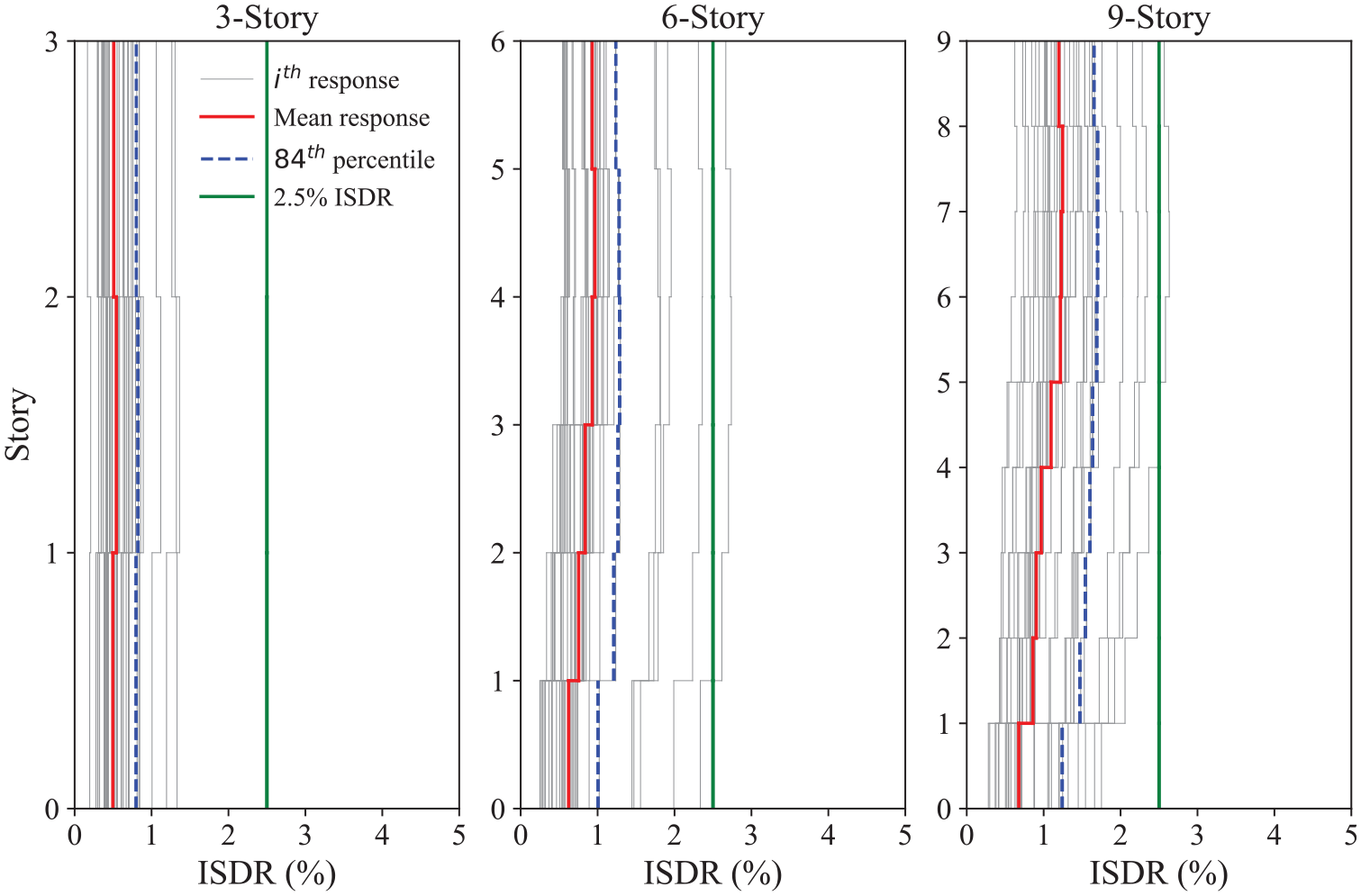
Comparison of story drift responses with design target drift.
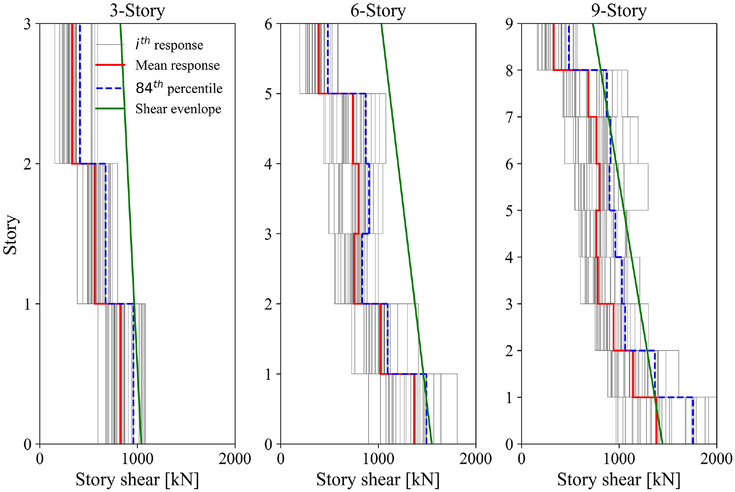
Comparison of story shear responses with target shear envelope.
Ground motion selection and scaling for IDA
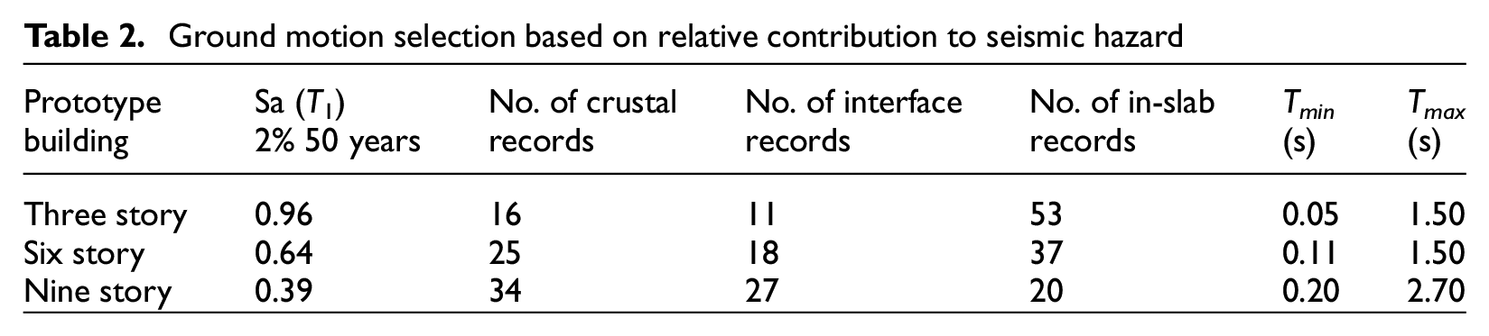
To conduct IDA, hazard-specific ensembles of ground motions were selected to best capture the tectonic characteristics of southwestern BC. They covered three contributing regimes: active shallow crust, subduction interface, and deep in-slab (Goda, 2019; Tesfamariam et al., 2023). For ground motion selection, structural- and site-specific conditional spectra (CS) were used as targets (Baker, 2011; Baker and Lee, 2018). Probabilistic seismic hazard analyses (PSHA) were first carried out using the OpenQuake Engine (Pagani et al., 2014) and the command files for SHM6 prepared by Natural Resources Canada (NRCan) (Kolaj et al., 2020). After the location of interest, soil condition, annual probability of exceedance, and the desired intensity measurement were specified in the command file, PSHA produced the seismic hazard curve, the UHS, and the disaggregation. A ground motion selection and scaling tool developed in the study by Tesfamariam et al. (2023), which is based on SHM6 and NBCC 2020, was utilized. The input for this tool includes the return period, the required number of ground motions, an anchoring period (
Ground motion selection based on relative contribution to seismic hazard
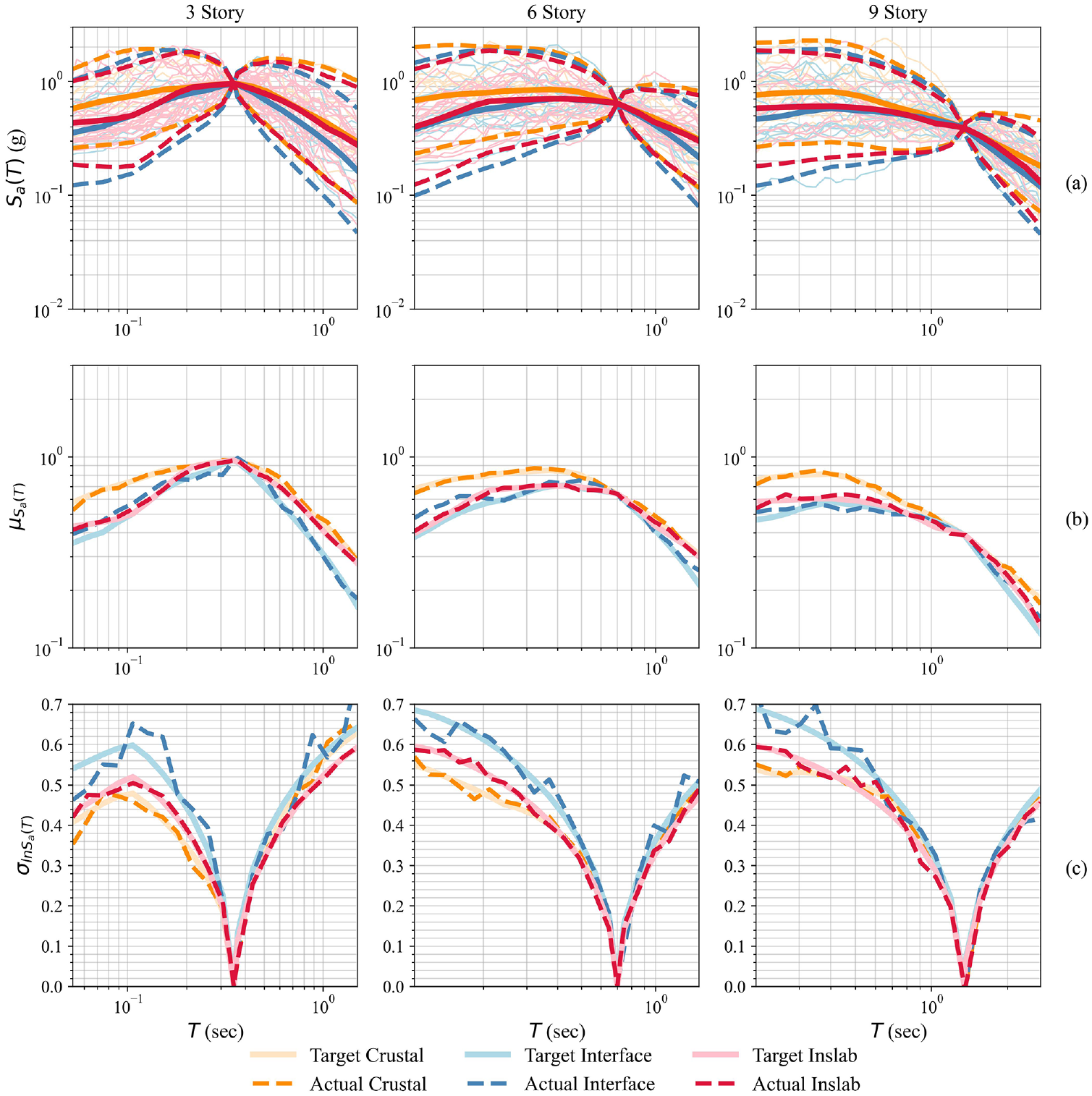
Scaled records for each prototype building: (a) pseudo-response spectra of individual records; (b) target and achieved conditional means; and (c) target and achieved covariances for the conditional spectra.
IDA and collapse fragility assessment
IDA was performed to assess the building’s fragility by scaling up each ground motion record until any one of the considered simulated and non-simulated collapse criteria was triggered (i.e. the occurrence of building collapse) (Vamvatsikos and Cornell, 2002). To enhance computational efficiency, the hunt and fill algorithm was used. Figure 13 presents the IDA results with 16%, 50%, and 84% statistics.
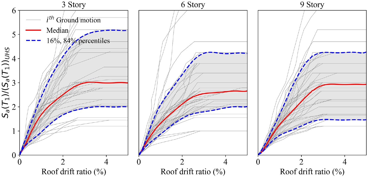
Incremental dynamic analysis results for the three analyzed buildings.
Fragility assessment was carried out based on the IDA results by fitting the building collapse at each intensity measurement level to a lognormal distribution (Figure 14). The CMR, which is the ratio of spectral acceleration resulting in 50% collapse of a building and the spectral acceleration at the MCE level, was quantified based on IDA results. For three-, six-, and nine-story prototype buildings, the CMR values are 3.4, 3.12, and 2.71. Note that FEMA P695 (FEMA, 2009) further suggests applying the spectral shape factor (SSF) to obtain the adjusted CMR (ACMR), which accounts for the bias introduced by the spectral shape of the ground motion suite. However, the SSF for the ground motion suite in this study was not available and applying the SSF would have lowered the collapse probability (Kovacs and Wiebe, 2019). Therefore, the ACMR for each building prototype was assumed to be conservatively the same as the CMR.
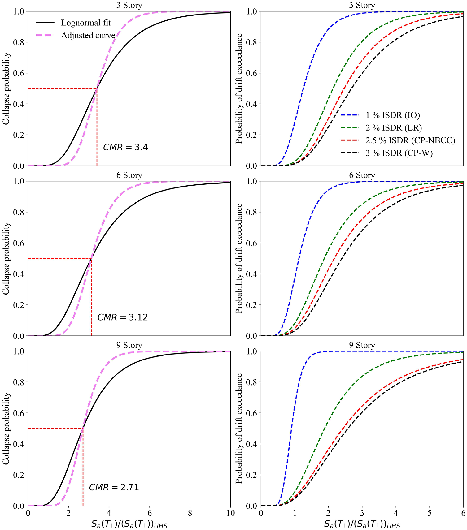
Collapse fragilities (left) and fragilities for drift of exceedance (right).
To check the CMR again for acceptable values, the total system collapse uncertainty,
Summary and conclusion
This study designed and examined the seismic performance of three-, six-, and nine-story mass timber buildings with PT-CLT shear walls coupled with UFPs. The DDBD approach was applied to design the prototype buildings for the seismicity of Vancouver (metropolitan city in Southwestern British Columbia, Canada), where three tectonic regimes coexist and increased seismic hazard resulted from the adoption of SHM6 in NBCC 2020. 2D fiber-based numerical models were developed in OpenSeesPy and validated to perform NLSA, NLRHA, and IDA. To perform collapse fragility assessment, IDA was conducted using 80 ground motions that were selected for each building and scaled to each seismotectonic regime’s CS. The following conclusions can be drawn from this study:
The 2D fiber-based numerical models were proven to be robust. Validations using full-scale quasi-static and shaking table experimental tests revealed their capability in capturing the response of PT-CLT walls with UFPs.
NLSA indicated the satisfactory structural performance of the prototype buildings. According to NLSA results, for three- and six-story buildings, the incipient crushing of CLT occurred at 3% roof drift and for nine-story buildings, at 2.4%. Since the DDBD approach considered 2% roof drift as the design target under the MCE event, satisfactory structural performance of the prototype building can be demonstrated as damages due to CLT crushing can be effectively limited.
The NLRHA results indicate that the DDBD method resulted in designs that met the design target (2% roof drift) at the MCE level. Moreover, none of the ground motions resulted in an ISDR surpassing the 2.5% limit from NBCC 2020 for the three-story building. For the six-story and nine-story buildings, only one instance out of 33 led to exceeding this limit.
From IDA, the CMRs for the three-, six-, and nine-story buildings were 3.4, 3.12, and 2.71, respectively. All values are considered satisfactory compared with the suggested threshold specified in FEMA P695. Based on fragility analysis, the collapse probabilities for all buildings were significantly lower than 10% under MCE. The probabilities of exceeding the CP-NBCC for the three-, six-, and nine-story buildings were 1.6%, 4.6%, and 5%, respectively, and were 1.2%, 2%, and 4.5% for CP-W. Overall, the studiedPT-CLT shear wall buildings exhibited good seismic performance and have the potential for application in Canada’s high seismic-risk zones as a primary SFRS.
Footnotes
Declaration of conflicting interests
The author(s) declared no potential conflicts of interest with respect to the research, authorship, and/or publication of this article.
Funding
The author(s) disclosed receipt of the following financial support for the research, authorship, and/or publication of this article: The Natural Sciences and Engineering Research Council of Canada (NSERC) Discovery Grant Awards (grant no. RGPIN-2023-03560) and the McGill MUESMA scholarship supported this research.
Data and resources
The authors would like to thank FPInnovations for sharing their experimental data that were used for OpenSeesPy model calibration and validation. The experimental data from FPInnovations are presented and available in the article by Chen et al. (2020). In addition, the NHERI two-story shaking table test data used for building-level model validation is available in DesignSafe data repository at https://doi.org//10.17603/ds2-zcb9-ry11, Ref. No. PRJ-1717. The open access and data transparency is hereby greatly appreciated. Crustal and in-slab ground motions selected for IDA were obtained from PEER NGA-West2 at https://ngawest2.berkeley.edu/site [last accessed January 2024]. For subduction event, ground motion records were selected from KiK-net at ![]() / [last accessed January 2024]. The authors acknowledge Solomon Tesfamariam for generously sharing ground motion selection and scaling tools used for IDA.
/ [last accessed January 2024]. The authors acknowledge Solomon Tesfamariam for generously sharing ground motion selection and scaling tools used for IDA.