
Abstract
The cross-laminated timber coupled wall (CLT-CW) system, a recently proposed timber-based structural system, has limited understanding of its seismic performance. The existing research in probabilistic seismic fragility assessment (PSFA) of CLT buildings reveals gap, particularly regarding comprehensive evaluation of CLT-CW systems and the impact of its various design parameters. To fully describe the state of the post-earthquake performance of structures, state-of-the-art studies recommend using multi-variate fragility analysis. Accordingly, this article presents a bi-variate PSFA of CLT-CW systems using two engineering demand parameters: the maximum and residual inter-story drift ratios. For the seismicity of Vancouver, British Columbia, Canada, 11 prototype buildings are evaluated considering different design parameters: coupling ratio, coupling beam shear force profile, CLT wall configuration, building story height, and ductility-related seismic force modification factor. Bi-dimensional numerical models of the systems are developed in OpenSees, and incremental dynamic analyses are performed using 30 ground motion records. Three limit state capacities and three limit state function combinations are utilized to develop probabilistic seismic fragility curves. The fragility curves under the different limit state function combinations are compared, and the effect of the different design parameters is investigated. This study contributes to a deeper understanding of the seismic performance of CLT-CW systems, assisting engineers and researchers in assessing seismic risk and developing seismic-resilient structures.
Keywords
Introduction
Over the past few years, timber-based constructions have experienced a resurgence in popularity due to the continuing urban densification, the need for sustainable construction materials, and the rapid development of high-performance engineered wood products (Milaj et al., 2017). Cross-laminated timber (CLT), a panel-type engineered wood product made of orthogonally stacked layers of dry lumber boards, has been effectively utilized as a floor and wall structural elements in multi-story timber buildings (Izzi et al., 2018; Tannert et al., 2018). Two primary construction methods, platform and balloon framing, are employed for CLT wall systems (Karacabeyli and Gagnon, 2019). In platform construction, the CLT floor panel at each story acts as a platform for erecting structural members at the upper story (Karacabeyli and Gagnon, 2019). While this approach is widely used for low-to-medium rise buildings (Sandoli et al., 2021), it has limitations when applied to taller structures (Chen and Popovski, 2020). In contrast, balloon framing incorporates continuous CLT wall panels that span multiple stories, with CLT floor panels attached to the sides of wall panels at each level (Karacabeyli and Gagnon, 2019). This technique effectively reduce the compression buildup on floor panels and minimize the distribution of connections and fasteners (Shahnewaz et al., 2021; Wang et al., 2023). The CLT coupled wall (CLT-CW) system (Tesfamariam et al., 2021a; Teweldebrhan et al., 2022; Teweldebrhan and Tesfamariam, 2022) is a noteworthy addition to the state-of-the-art knowledge in balloon-type CLT construction. The seismic performance of individual CLT panels and platform-framed CLT shear walls has been widely explored in literature (e.g. Shahnewaz et al., 2020; van de Lindt et al., 2019); however, the seismic research on balloon-framed CLT systems remains incomplete and there remain research topics worthy of investigation (Shahnewaz et al., 2021; Tesfamariam and Teweldebrhan, 2023). Given CLT-CW systems are a relatively new structural solution, with unique structural characteristics and energy dissipation mechanism (Teweldebrhan and Tesfamariam, 2022), their performance under seismic loading, including responses to varying seismic hazard levels and the impact of different design parameters, has not yet been thoroughly investigated. This study aims to address this knowledge gap and provide insights into the seismic performance of CLT-CW systems.
The most common approach to evaluate the seismic performance of a system is through probabilistic seismic fragility assessment (PSFA) (Cornell et al., 2002). Integral to performance-based earthquake engineering methodology, PSFA enables the computation of fragility curves (FCs) that provide the probability of a structure or its components reaching a specific damage state (i.e. exceeding a given limit state) under a given intensity of ground motion (GM). The observed structural damage can be defined in terms of strength, displacement, damage, or energy (Feng et al., 2023). In literature, the maximum inter-story drift ratio (MaxISDR), residual inter-story drift ratio (ResISDR), and peak floor acceleration are of the most common engineering demand parameters (EDPs) employed to develop the seismic fragility of the structural and nonstructural components of structural systems (Hu and Wang, 2021; Tesfamariam and Goda, 2015; Yakhchalian et al., 2021). The traditional PSFA, which typically considers a single EDP, often fails to fully capture the post-earthquake performance of structures (Ataei and Padgett, 2013; Uma et al., 2010). In practice, multiple structural components may contribute to the global structural performance (Mangalathu et al., 2018). Moreover, structural and nonstructural components are vulnerable to different EDPs (De Risi et al., 2019). Besides, when comparing structural or design alternatives, an alternative can exhibit lower MaxISDR but higher ResISDR, indicating good performance during the earthquake but poor post-earthquake functionality and vice versa (Feng et al., 2023). To overcome these limitations, recent studies (e.g. Cimellaro and Reinhorn, 2011; De Risi et al., 2019; Feng et al., 2023; Mangalathu et al., 2018) have proposed PSFA based on multiple EDPs (mEDPs). With mEDPs-based FCs, a comprehensive description of system performance can be obtained to make more informed and direct decisions (Feng et al., 2023).
Applying these principles, this study utilizes two EDPs (MaxISDR and ResISDR) to develop non-collapse FCs and investigate the PSFA of CLT-CW systems. The selection of these specific EDPs is driven by several factors. First, their ability to represent two significant aspects of seismic structural performance of the system: deformation and repairability (Feng et al., 2023). Post-earthquake damage investigations have revealed that large deformations are the primary cause of damage in both structural and nonstructural components (FEMA P-58-1, 2018). On the other hand, with the growing attention on resilience of structures, ResISDR has emerged as a vital index that serves as a measure of the repairability or functionality of the structural system after an earthquake event (FEMA P-58-1, 2018). Second, both the EDPs are easily compute-able damage indicators with well-established performance limit state thresholds. To this effect, several researchers have utilized these EDPs for PSFA, particularly in the context of timber-based structural systems (e.g. Luo et al., 2022; Sun et al., 2019). However, in those studies, both EDPs were employed independently, which makes decision indirect, and lacks sufficient consideration of the correlations among different EDPs (Du and Padgett, 2020). In the PSFA of CLT- CW system, both MaxISDR and ResISDR hold importance. A recent study by You et al. (2023) indicates that although MaxISDR is the primary damage indicator for CLT-CW system, ResISDR also plays a significant role from a resilience-focused perspective. Remarkably, nearly 80% of total repair costs of damaged structural components are attributed to the damage of coupling beams due to residual deformation. As a result, the design choices of different design parameters (presented as cases in this study) can be influenced by ResISDR, which can only be captured using mEDP-based PSFA.
The PSFA of the CLT-CW system is assessed for 11 prototype buildings, categorized into six cases to study the effects of different design parameters. The baseline case features a 15-story symmetrical CW system with uniform coupling beam strength, a 30% coupling ratio
Building details
The current study is based on the outcomes of a recently completed research project, funded by the British Columbia Forestry Innovation Investment Ltd., in terms of building information, design details, modeling, and selected GM records (Tesfamariam et al., 2021a; Teweldebrhan et al., 2022; Teweldebrhan and Tesfamariam, 2022). The structural system comprises CLT balloon shear-walls, CLT floor panels, glulam beams and columns, steel coupling beams with replaceable shear-links, and buckling-restrained brace (BRB) hold-downs (Figure 1). In this system, the glulam beams and columns were designed to support the vertical gravity load of the system, and the balloon CLT shear walls, coupling beams, and hold-downs were designed to resist the seismic force. The building was assumed to be located in Vancouver, and the associated snow and seismic loads were determined based on the provisions of the National Building Code of Canada (NBC, 2020), considering a class C soil condition. Analyses were performed using the ETABS program, and all the timber elements were designed following the CSA 086-19 standard (2019). The complete design procedure, along with a numerical example, can be found in Tesfamariam et al. (2021a), Teweldebrhan et al. (2022) and Teweldebrhan and Tesfamariam (2022).
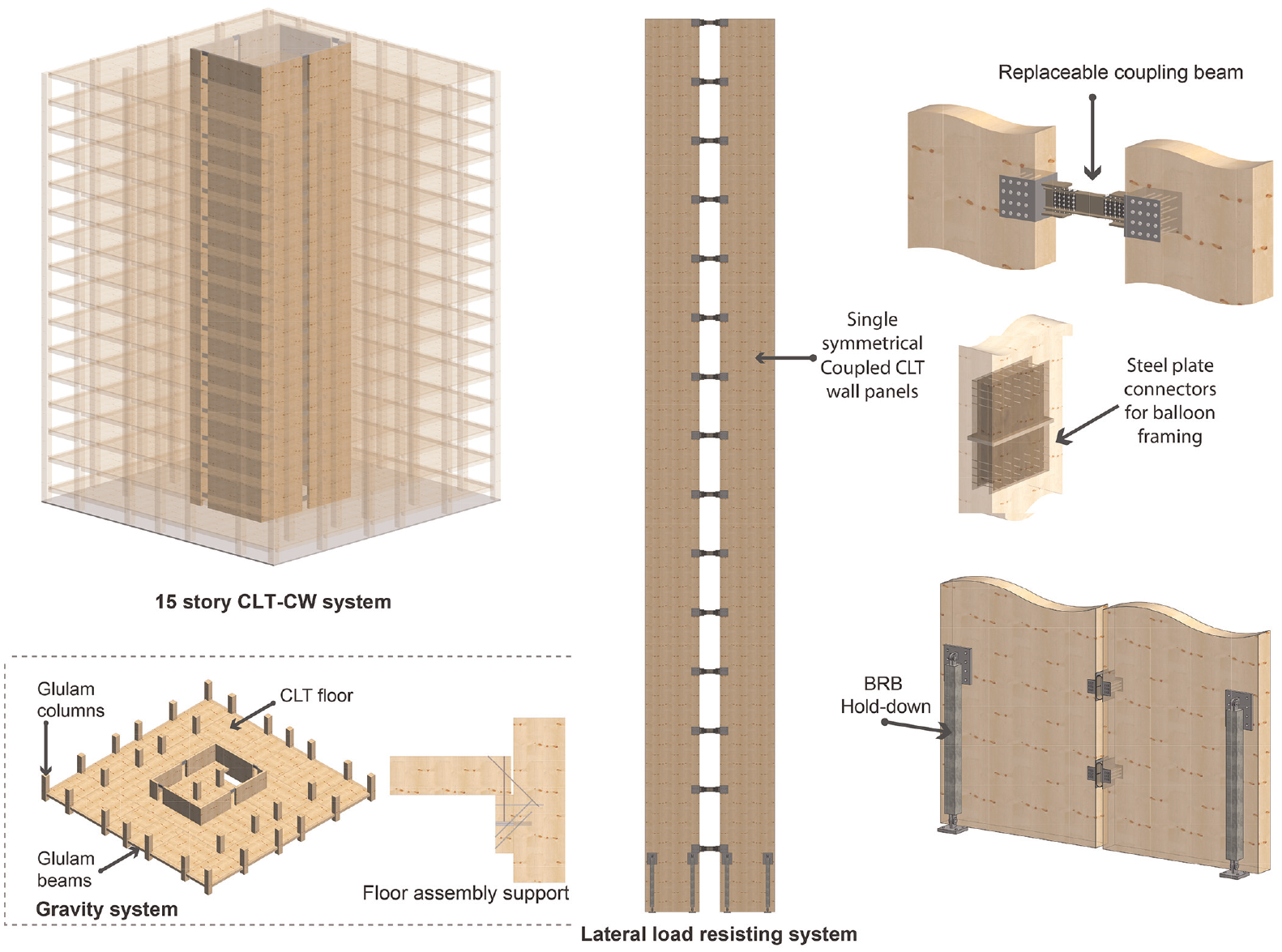
CLT-CW system components.
A total of 11 different CLT-CW systems are developed to study the effect of five design parameters (

where
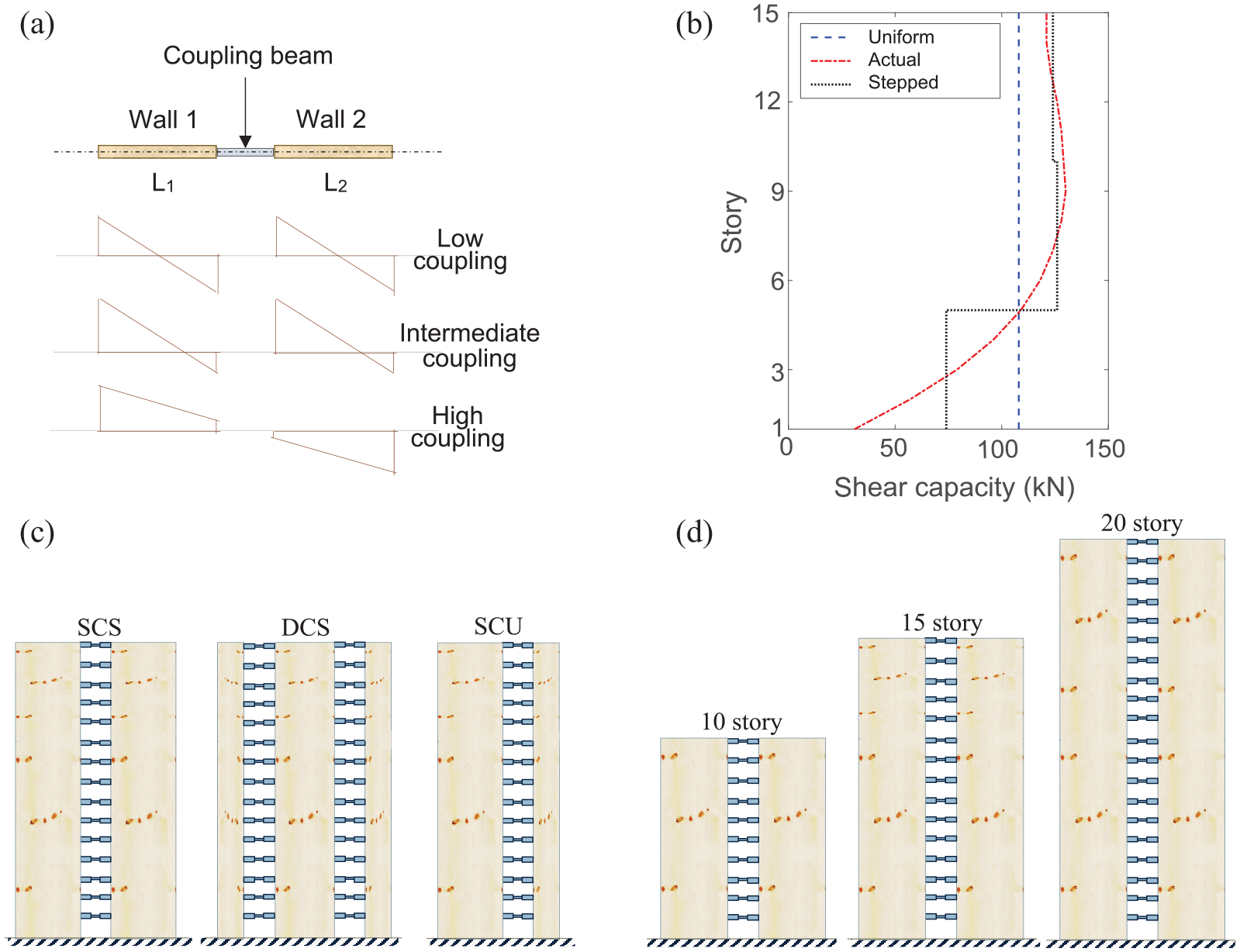
CLT-CW systems with different: (a) CR values and strain diagrams, (b) coupling beam shear force profiles, (c) CLT wall configurations, and (d) story heights.
Base shear modification factors (termed
Case study description
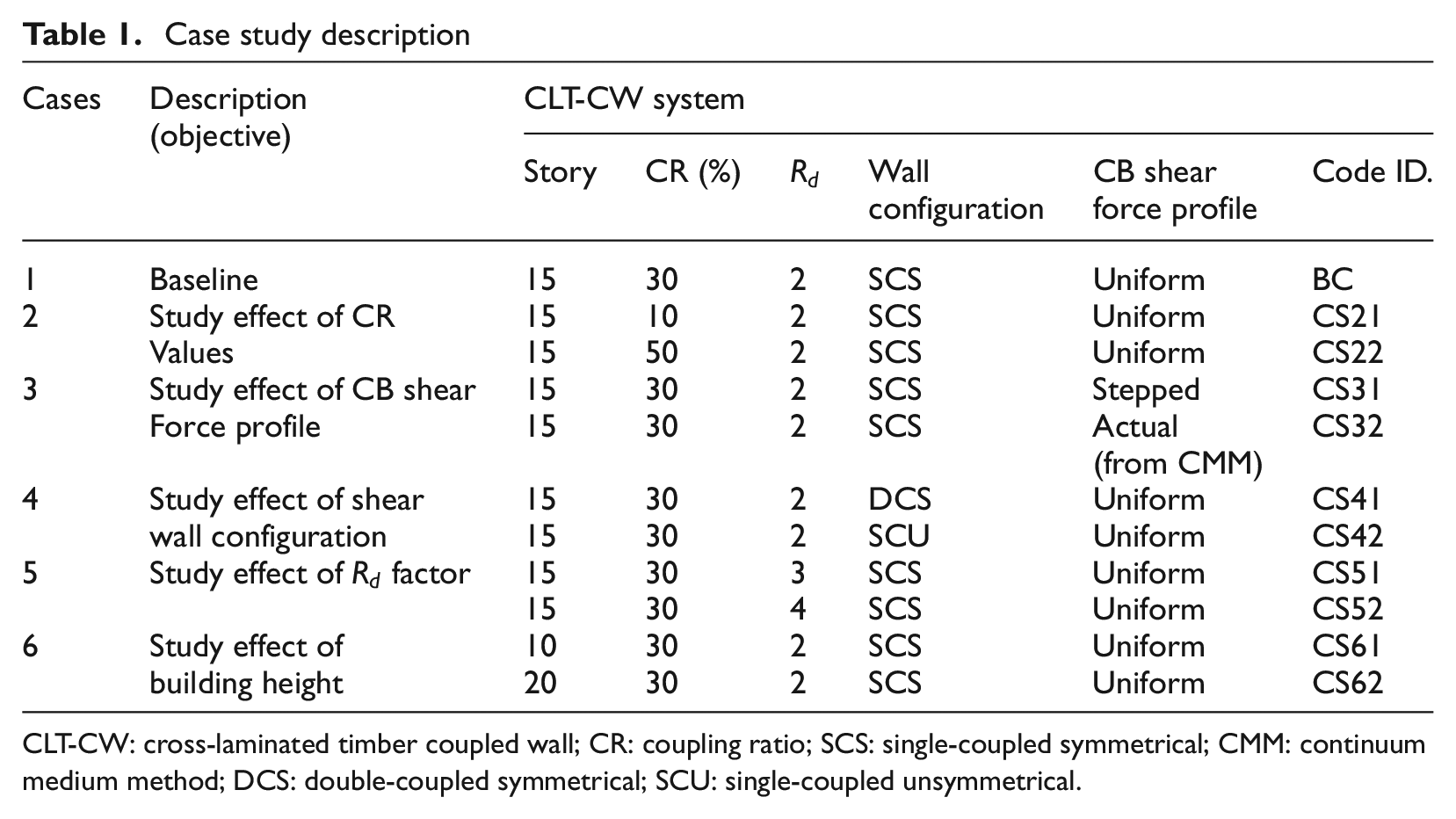
CLT-CW: cross-laminated timber coupled wall; CR: coupling ratio; SCS: single-coupled symmetrical; CMM: continuum medium method; DCS: double-coupled symmetrical; SCU: single-coupled unsymmetrical.
Seismic hazard and GM selection
Three seismic sources—crustal, in-slab, and interface—significantly contribute to seismic hazards in Vancouver, British Columbia (Halchuk et al., 2014). This study uses a multiple conditional mean spectra (CMS) record selection method to represent the distinct response spectral features of these earthquake sources and their overall seismic hazard contributions (Goda, 2019). The initial inputs of this method include the return period
In this study, the first fundamental period of the prototype buildings ranges from 0.7 s to 2.0 s (Table 3). Accordingly, three sets of 30 GM records (bi-directional)—that possess the key features (e.g. magnitude, frequency content, and duration) of the considered seismic sources are selected at
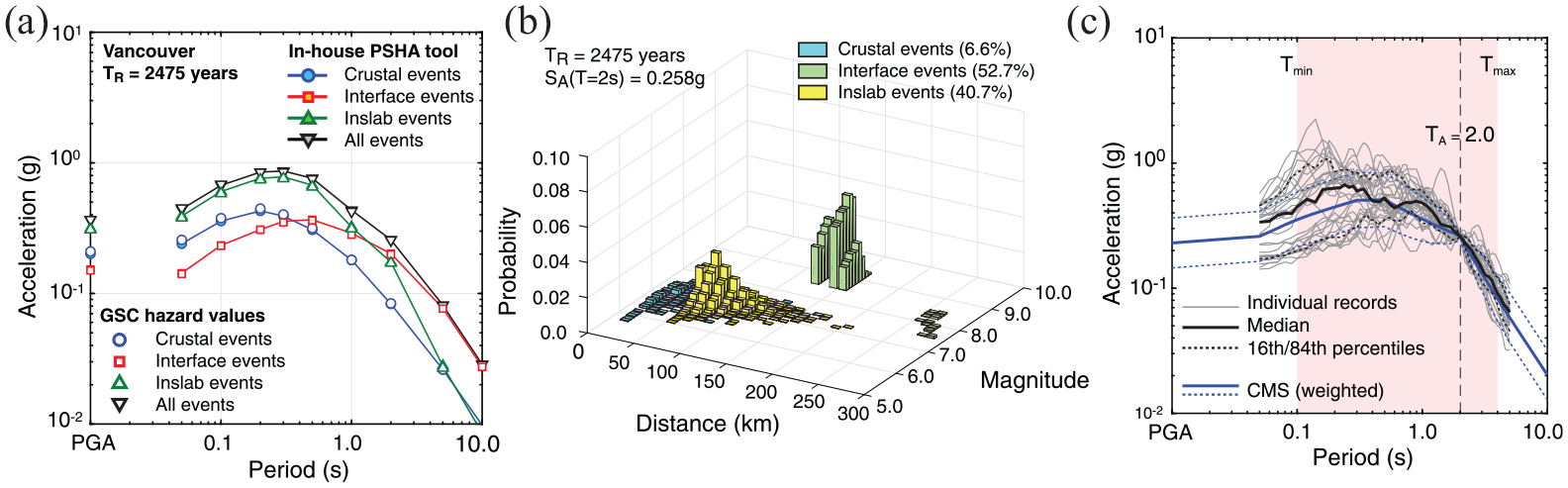
Vancouver’s seismic: (a) hazard curve, (b) disaggregation for spectral acceleration at 2.0 s, and (c) response spectra of the selected records at
Multi-variate fragility analysis
Demand parameters
As mentioned earlier, two EDPs (MaxISDR and ResISDR) are used to assess the performance of the CLT-CW system. MaxISDR is a direct measure of building’s performance, and it denotes the maximum (absolute) difference in lateral displacement between two consecutive floors divided by the story height. ResISDR, on the other hand, represents the maximum story drift ratio recorded at the end of the GM time history. For decision-making and a proper understanding of the system performance, the relationship between structural demand and capacity should be explored (Powell, 2010). Accordingly, in this study, the demand-to-capacity ratio
Limit state capacities for MaxISDR and ResISDR (DeVall, 2003; FEMA P-58-1, 2018)
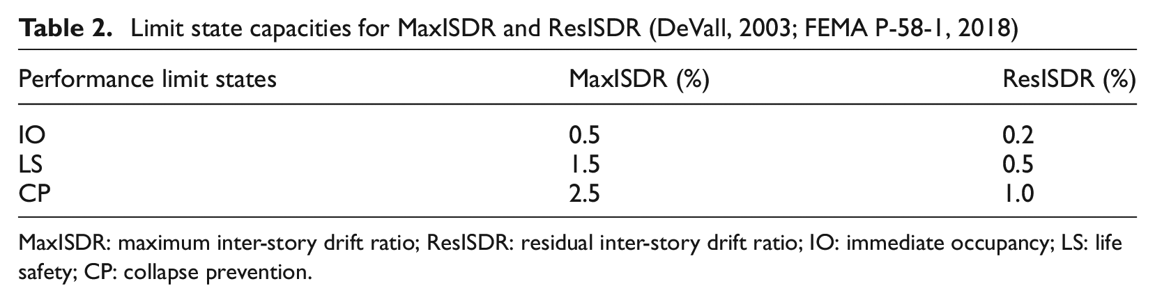
MaxISDR: maximum inter-story drift ratio; ResISDR: residual inter-story drift ratio; IO: immediate occupancy; LS: life safety; CP: collapse prevention.
Demand parameter combinations
Due to the uncertainty of LSSs, different damage measure combinations are proposed in literature (e.g. Cimellaro and Reinhorn, 2011; De Risi et al., 2019; Feng et al., 2023). Those LSSs are selected to represent a broad spectrum of possible functions and reasonably quantify the post-earthquake performance of a system. The bi-variate combination proposed by Feng et al. (2023) is expressed as the weighted average of the individual EDPs. Whereas the LSSs proposed by Cimellaro and Reinhorn (2011) and De Risi et al. (2019) consider linear, non-linear, dependent, and independent combinations of the individual EDPs. The result of the weighted average method underestimates the probability of exceedance (PE) of a system under a given performance limit state. The latter formulations, on the other hand, result in a greater PE. Accordingly, in this study, three multi-variate LSSs (MvLSSs) proposed by De Risi et al. (2019) are utilized: linear, circular, and square, and their expression is given by (Equations 2–4), respectively. Figure 4 depicts the 3D and 2D views of the LSS for two generic EDPs


where
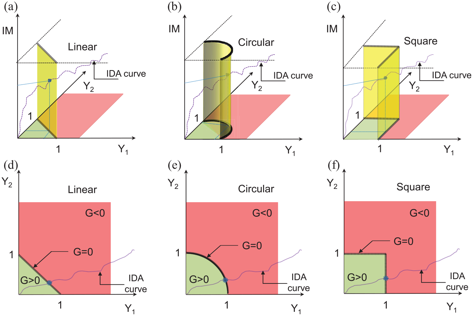
Limit state surfaces for two EDPs, adapted from De Risi et al. (2019): (a) and (d): linear, (b) and (e): circular, (c) and (f): square.
Fragility curves
The literature proposes different parametric and non-parametric fitting models to develop seismic FCs. Considering its simplicity, good representation, and convenient characteristics, the lognormal cumulative distribution function (CDF) has often been used (Cornell et al. 2002). Accordingly, the lognormal CDF is used, and the method of moments is applied to obtain the parameters of the distribution function at the damage threshold of interest (e.g. IO). These parameters (the mean and standard deviation) are then used to develop the FCs at the specific limit state condition. Analytically, for a single scalar damage measuring index, the resulting FC is described by the following equation (De Risi et al., 2019):
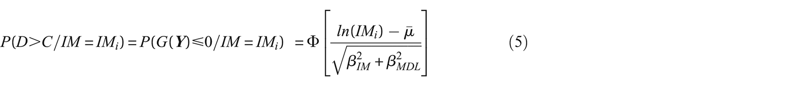
where


However, this study applies the fragility methodology based on the bi-variate damage indices. For the case of an MvLSS, the calculation of IM values corresponding to the onset of a specific limit state is not straightforward. It is necessary to obtain the performance point
Numerical model
A finite element (FE) model for a 2D system was developed using Open System for Earthquake Engineering Simulation (McKenna et al., 2000). In this FE, framework the model is formed by assembling the structural components: CLT shear-wall elements, hold-downs, and coupling beams (Figure 5). The CLT wall panels are modeled using ElasticIsotropic material and quad elements (Demirci et al., 2018). To model the continuity of the CLT wall panels (for balloon systems), ZeroLength vertical and horizontal spring elements are utilized using uniaxialMaterial elastic materials (Teweldebrhan et al., 2022). The two ends and central “fuse” of the coupling beams are modeled using OpenSees elasticBeamColumn elements as rigid offsets and Steel01 UniaxialMaterial ZeroLength non-linear vertical springs, respectively (Ji and Molina Hutt, 2020; Zona et al., 2018). To satisfy the high axial demand, BRB hold-downs are utilized, and OpenSees Steel01 uniaxialMaterial with ZeroLength element is used (Tesfamariam et al., 2021b). The contact between the CLT wall and the base is modeled using OpenSees uniaxial elastic notension (ENT) material. A large elastic stiffness value is assigned to the ENT spring under compression. Besides, a leaning column is introduced and modeled as an elasticBeamColumn element to account for the P-delta effect. Elastic UniaxialMaterial and truss elements are used to link the CLT shear walls and leaning column and transfer the P-delta effect. The reader can refer to Tesfamariam et al. (2021a) for the detailed modeling and parameters of the CLT-CW system. Using the developed OpenSees numerical model, modal analyses are performed, and the first three fundamental periods of the CLT-CW systems are obtained (Table 3). Note that, in all the prototype CLT-CW buildings, large difference is exhibited between mode 1 and mode 2. This is attributed to the fact that the lateral displacement of the CLT-CW system is dominated by rocking, which is consistent with the deformation objective of the CSA standard (Teweldebrhan and Tesfamariam, 2022).
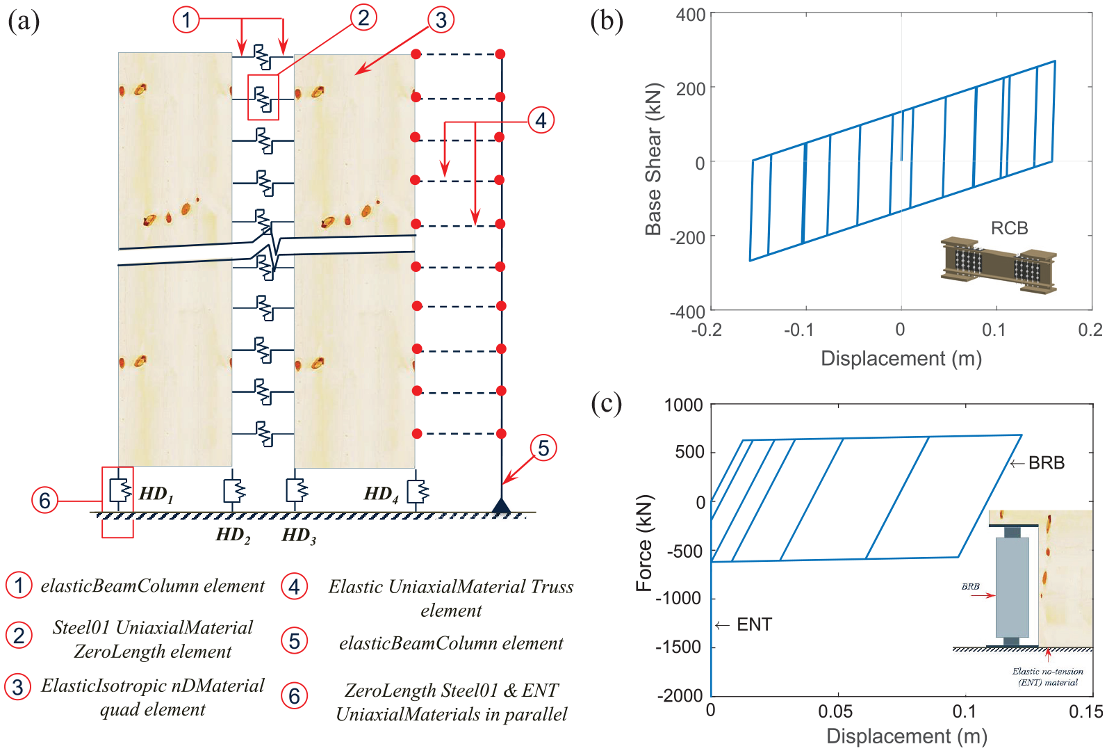
Numerical model: (a) CLT-CW system, (b) hysteric response of coupling beam, and (c) hysteric response of BRB hold-down.
Fundamental periods of the prototype buildings and GM selection parameters
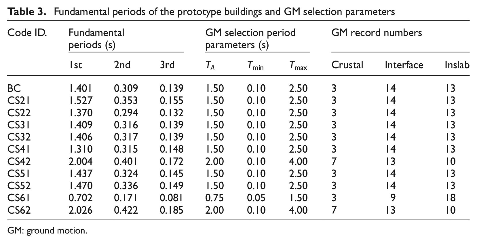
GM: ground motion.
Result and discussion
Incremental dynamic analysis
IDA is a series of dynamic analyses performed by repeatedly scaling a GM record until a specific damage on the structure is attained (Vamvatsikos and Cornell, 2002). The resulting curve relates the scaled IM values with one or more structural EDPs or, alternatively, damage measures. Due to the dominance of the first mode, in this study, the 5%-damped spectral acceleration at the fundamental period of the system
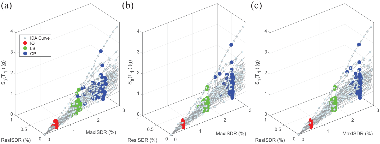
3D IDA curves for the baseline system considering: (a) linear, (b) circular, and (c) square LSSs.
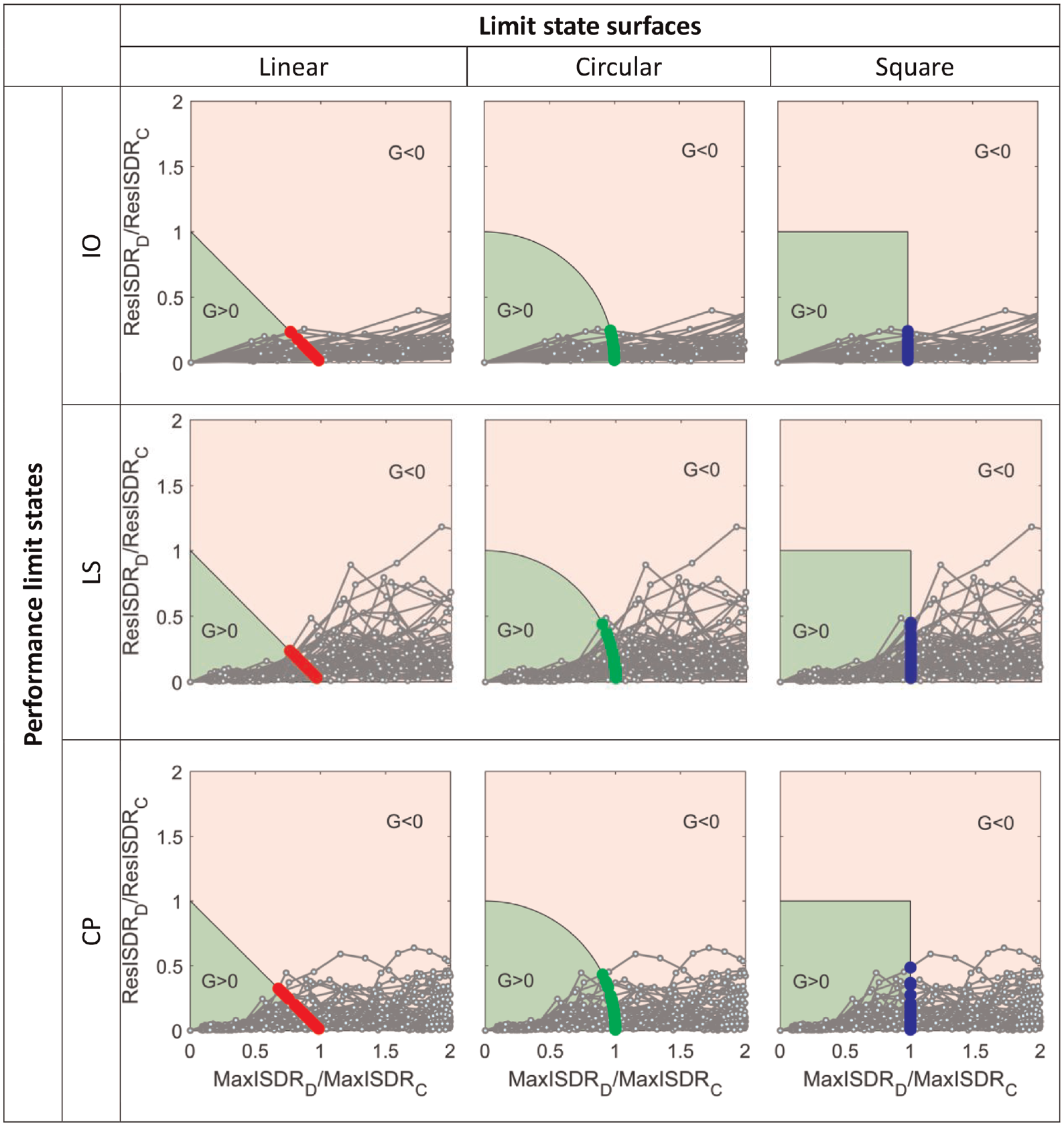
The 2D representation of the same IDAs, in terms of Ys, is shown in Figure 7. The vertical and horizontal axes of the figure represent the normalized ratio between the demand and capacity of MaxISDR and ResISDR, respectively. Three important notes can be made from Figure 7. First, for the case of the square LSSs, the proposed procedure coincident with the classic procedure adopted for the case of sEDP-based fragility analysis (based on the MaxISDR EDP only). Second, when the
Two-dimensional IDA curves for the baseline.
Bi-variate EDP-based FCs
As discussed in the previous sections, the seismic fragility of the designed CLT-CW systems is examined under IO, LS, and CP limit states. The performance points are first estimated considering the three limit state functions. Once the
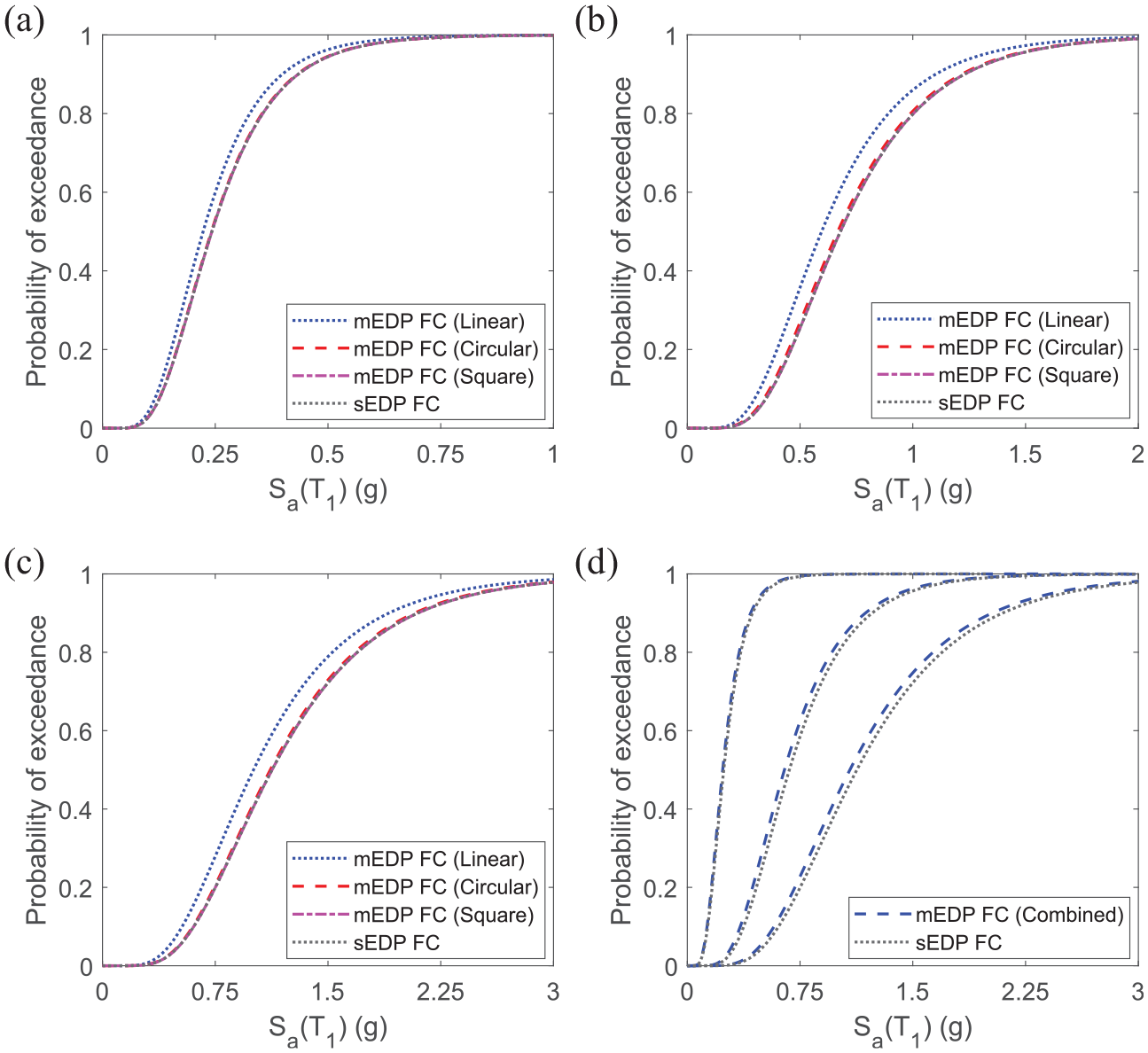
Non-collapse baseline fragility curves: (a) IO, (b) LS, (c) CP, and (d) combined equivalent FCs.
From the mEDP FCs shown in Figure 8a to c, two extreme cases are noted. The circular and square LSSs almost yield the same FCs as the sEDP FC, whereas the linear LSS tends to capture the effect of ResISDR at the highest level. However, these LSSs are uncertain (Cimellaro and Reinhorn, 2011; De Risi et al., 2019). Thus, a further FC is developed by combining the effect of these three LSSs. Each mEDP FC was constructed by the cumulative lognormal distribution of the 60 (= the number of GMs) performance points. Accordingly, 180 performance points from the three the LSSs are combined, and their cumulative lognormal distribution is obtained. The same procedure is repeated for each of the performance limit states to yield Figure 8d. These FCs represent the combined effect of the considered LSSs and hence, named as equivalent FC (De Risi et al., 2019). Three points can be noted from the figure. First, the combined mEDP FC aggregates the effect of the original LSSs and gives an intermediate result or FCs. Second, the combined mEDP FC results in higher PE and considers the impact of both the EDPs (MaxISDR and ResISDR) to provide a complete picture of the system performance with respect to the chosen EDPs. Third, the difference between the combined mEDP FCs and the sEDP FCs increases as the system goes from the linear (IO) to the non-linear (CP) zone. Moreover, the dispersion increases from IO to CP. Generally, the equivalent mEDP FCs limit the uncertainty of each of the defined LSSs and provide a combined result. Thus, the discussion on the result of the rest of the case studies will be based on the combined mEDP FCs and sEDP FCs. Quantitatively, the PE and the observed differences are summarized in Table 4.
PE (%) and the change in PE (%) of the mEDP FCs (with respect to the sEDP FC) of the baseline study at different performance limit states
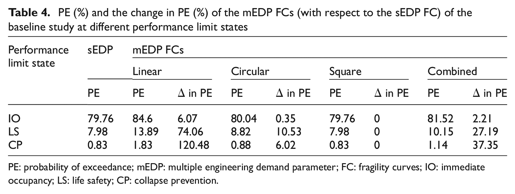
PE: probability of exceedance; mEDP: multiple engineering demand parameter; FC: fragility curves; IO: immediate occupancy; LS: life safety; CP: collapse prevention.
Effect of coupling ratio
This section discusses explicitly the effect of
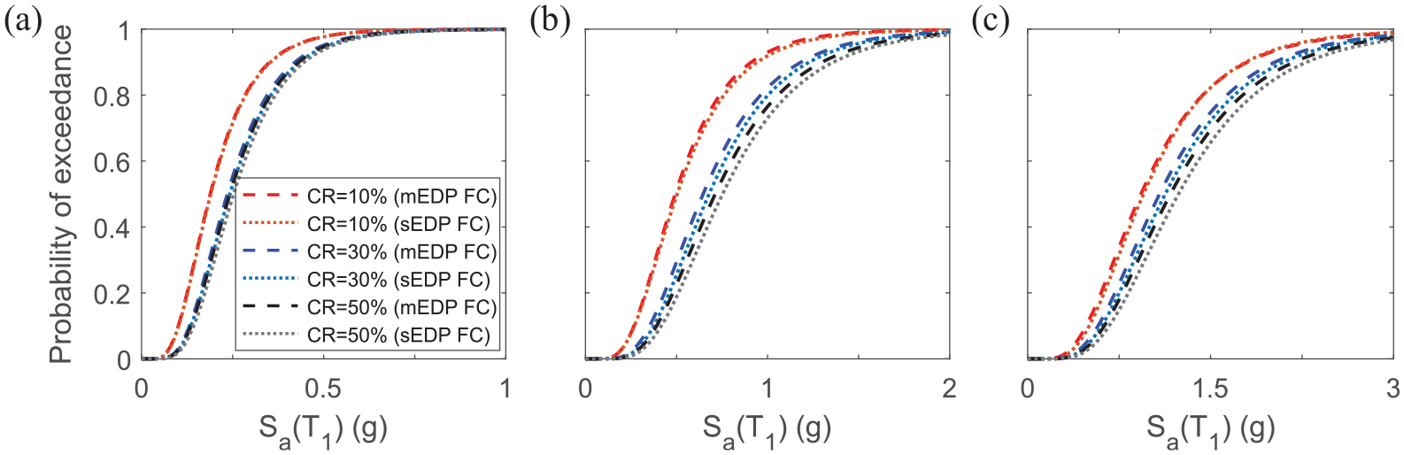
Effect of coupling ratio on the non-collapse fragility curves at: (a) IO, (b) LS, and (c) CP.
Effect of coupling beam shear profiles
For the same
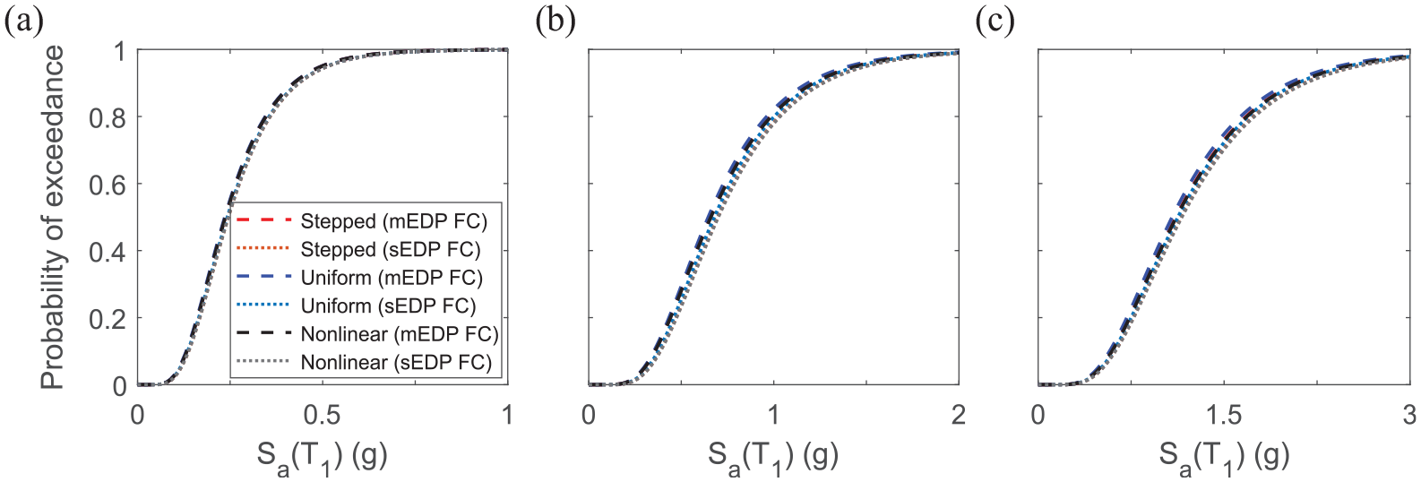
Effect of shear force profile on the non-collapse fragility curves at: (a) IO, (b) LS, and (c) CP.
Effect of wall configuration
Three CW configurations (Figure 2c)—SCS, DCS, and SCU are considered to examine the effect of different wall configurations on the fragility of the CLT-CW system. Detailed design and model information of those systems can be found in Teweldebrhan et al. (2022). Figure 11 illustrates the effect of these wall configurations on the FCs of the system. As can be seen from the figure, CLT-CW systems with the SCU wall system are vulnerable to intense earthquake excitations. SCS and DCS have better performances at all the performance limit state levels. Moreover, it is interesting to note that at the IO level (Figure 11a), DCS has a higher performance than SCS (PE = 78.94%); however, the system exhibits a lower performance at the LS and CP limit states (PE = 11.78% and 1.23% at LS and CP, respectively). This is attributed to the fact that at a relatively lower GM intensity, the coupling beams in SCS (system with single coupling, four hold-downs, and higher wall flexural stiffnesses) yield earlier than those at DCS (system with double coupling, six hold-downs, and relatively lower wall flexural stiffnesses) and thus exhibits a lower performance. However, as the GM level increases, the coupling beam at DCS yields, their coupling action degrades, and the contribution of flexural walls activates to improve the performance of the SCS wall system. In summary, it is observed that system with SCU exhibits higher fragility or PE (97.37%, 27.75%, and 3.37% at IO, LS, and CP, respectively). In an ideal condition where a designer chooses wall configurations, SCU and DCS are recommended. The performance of the different wall configurations under different
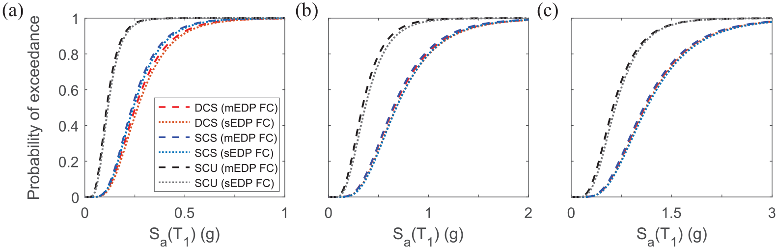
Effect of wall configurations on the non-collapse fragility curves at: (a) IO, (b) LS, and (c) CP.
Effect of ductility-related seismic modification factor
The CLT-CW system is a recently proposed tall timber building. For those new systems to be introduced in the building codes, their seismic performance must be evaluated considering different seismic force modification
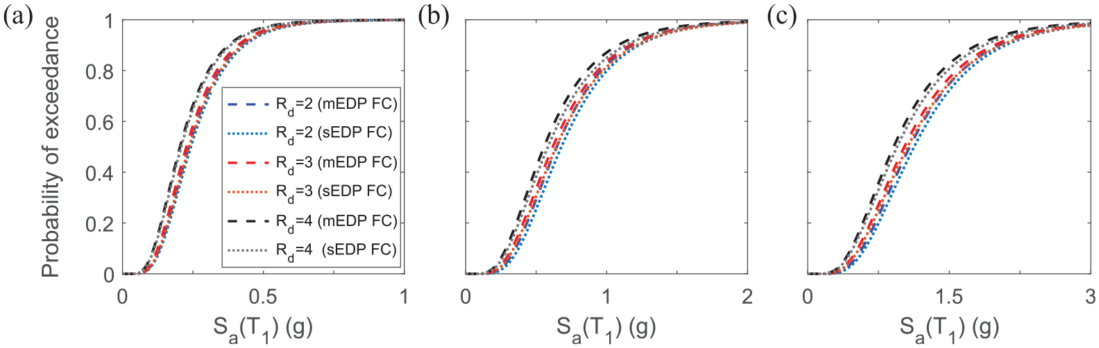
Effect of ductility-related factors on the non-collapse fragility curves at: (a) IO, (b) LS, and (c) CP.
Effect of building height
With the prevailing building height restriction in high-rise timber buildings, it is important to study the effect of story height on the fragility of the proposed system. Accordingly, two additional systems (10 and 20 stories) are designed with the same design details as the baseline. Figure 13 illustrates the effect of the different story heights on the performance of the system. As the CLT-CW systems are built taller and more slender, their seismic performances become lower. That is, the system with a lower story (e.g. 10) exhibits better seismic performance than the one with a higher level (e.g. 20). Relatively, the seismic performances of the 15 and 20-story systems are closer compared to the 10-story system (Table 5). The performance of the 10-story, by far better than the higher buildings. It is also noted that, relatively, there is a larger difference between the mEDP FCs and sEDP FCs in the 10-story than in the other story levels.
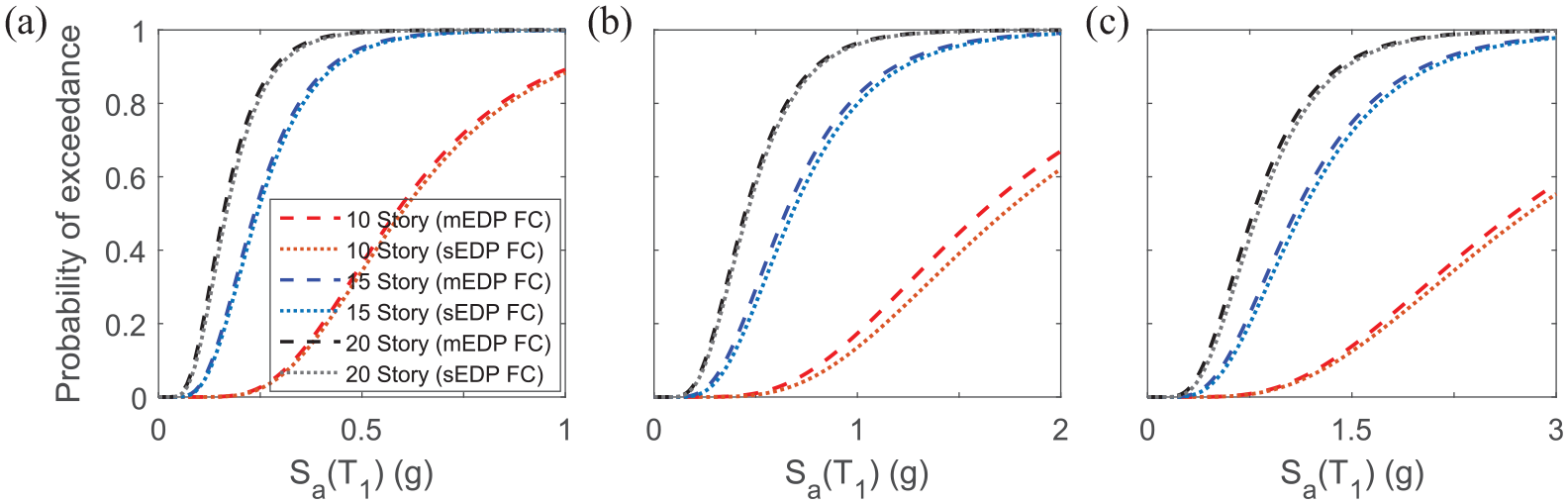
Effect of building height on the non-collapse fragility curves at: (a) IO, (b) LS, and (c) CP.
PE (%) and the change in PE (%) of the mEDP FCs (with respect to the sEDP FC) of the baseline study at different performance limit states
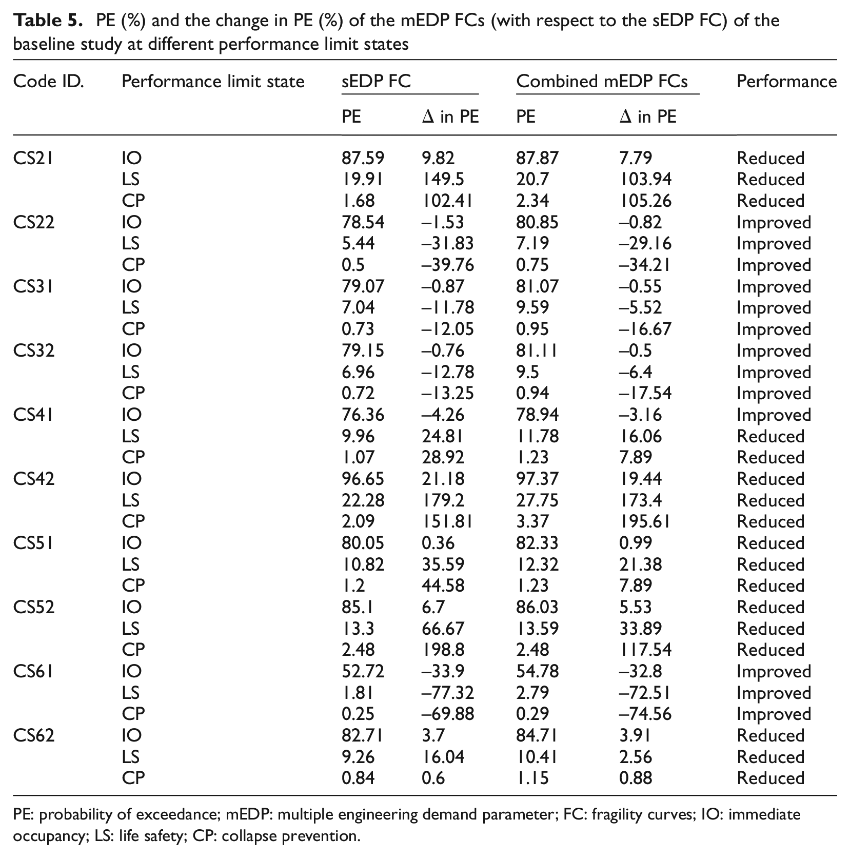
PE: probability of exceedance; mEDP: multiple engineering demand parameter; FC: fragility curves; IO: immediate occupancy; LS: life safety; CP: collapse prevention.
Summary
In the preceding section, the effect of the different design parameters on the fragility of the CLT-CW system is discussed. The parameters that enhance or worsen the performance of the system are identified. Table 5 provides the change in the PE of the different cases with respect to the PE of the baseline. The values in the table are both in terms of the sEDP and mEDP FCs. The value of PE for sEDP and mEDP are different and hence, the percentage change in the performance of the system. The values based on mEDP FCs consider the effect of both the EDPs and the different LSSs. Design parameters:
Conclusion
Timber-based constructions have experienced a resurgence in popularity over the past few years. One novel contribution to the state-of-the-art knowledge in CLT construction is the recently proposed CLT-CW system. When new structural systems are proposed, it is vital to study their seismic fragility. Seismic fragility assessment of structural systems requires the selection of appropriate EDPs. To capture the entire state of the post-earthquake performance of structures, state-of-the-art studies recommend the use of multi-variate probabilistic seismic fragility analysis. In this article, two EDPs—MaxISDR and ResISDR—are chosen, and multi-EDP-based FCs (mEDP FCs) are developed for 11 prototype buildings. The 2D numerical model of the systems is developed in OpenSees, and 3D IDA is performed using 30 (bi-directional) GM records that represent the seismicity of Vancouver, Canada. Three performance limit state levels—IO, LS, and CP—and three different combinations of LSSs, namely linear, circular, and square, are utilized to develop probabilistic seismic FCs. The 11 prototypes were categorized into six cases based on different design parameters. For each case, mEDP FCs and sEDP FCs were developed and the following conclusions were drawn:
For the 15-story baseline CLT-CW system, the resulting mEDP FCs for the circular and square LSSs overlap one over the other and the mEDP FC for the linear yields higher probability of exceedance (PE). This difference increases significantly at CP where the system exhibits non-linearity. Generally, for this system, the MaxISDR is found to govern the mEDP FCs with a marginal impact from ResISDR.
To prevent biases against the employed LLSs, a combined FC is developed, incorporating the effect of all three LSSs. The resulting equivalent mEDP FCs represent the combined effect of the considered LSSs and can capture the effect of both EDPs on the non-collapse FCs of the systems.
The system with a higher
The system with a uniform coupling beam shear force profile exhibits a lower performance (even though the difference is small). The actual profile (based on the CMM) leads to better performance. Nevertheless, a steeped profile with the same performance and ease of constructability would be a good design choice under an ideal design conditions.
The system with a SCU wall is shown to be more vulnerable seismically. The performance can be increased by using SCS and DCS CLT-CW systems.
The systems with higher story height and seismic modification factor exhibit lower performances than those with lower story height and seismic modification factors.
In summary, the use of mEDP FC provides more comprehensive descriptions of the fragility of the system, considering the two most important EDPs. Limitations of the sEDP FCs are noted in the results obtained. The effect of the different LSSs and their combined fragility analysis is observed. Moreover, the design parameters that enhance the seismic performance of the proposed systems are identified. This study, however, has some limitations. The only sources of non-linearity are the coupling beams and hold-downs. Degradation is not considered, the CLT to hold-down connections and CLT to coupling beam connections were modeled as rigid connections. Moreover, the CLT shear walls are modeled as single walls. The stated limitation warrants further investigations.
Footnotes
Authors’s Note
Solomon Tesfamariam is now affiliated to Department of Civil and Environmental Engineering, University of Waterloo.
Declaration of conflicting interests
The author(s) declared no potential conflicts of interest with respect to the research, authorship, and/or publication of this article.
Funding
The author(s) disclosed receipt of the following financial support for the research, authorship, and/or publication of this article: This research was funded to the last author by the British Columbia Forestry Innovation Investment’s (FII) Wood First Program and the Natural Science Engineering Research Council of Canada Discovery Grant (grant no. RGPIN-2019-05013).