
Abstract
There is limited research on enhancing the flexural performance of cross-laminated timber (CLT) panels made from fast-growing hardwood species like poplar, particularly using external reinforcements. This study aims to investigate the effect of aluminium (AL) and glass fibre-reinforced polymer (GFRP) sheets on the bending behaviour of 3-ply poplar CLT panels in both longitudinal (L) and transverse (T) directions. Four reinforcement configurations were tested. The results showed that AL reinforcement increased MOR by 53.9% (L) and 208% (T), and MOE by 56.9% (L) and 617% (T) of CLT samples. GFRP led to MOR gains of 37.4% (L) and 61.8% (T), and MOE gains of 38.3% (L) and 223% (T) in CLT samples. The most effective flexural performance in CLT samples was achieved with three layers of reinforcement, particularly with AL. Ductility of CLT samples also improved significantly: AL increased it by 76.6% (L) and 28% (T), while GFRP improved it by 47% (L) and 55% (T). These findings suggest that external reinforcement – especially with AL – can effectively enhance bending performance and ductility of poplar CLT, providing a viable strategy to improve its structural performance for broader application in engineered timber construction.
Introduction
Cross-laminated timber (CLT) is an engineered-wood product (EWP) composed of three or more layers of wood planks bonded orthogonally. This layered structure significantly reduces the impact of defects and uncertainty compared to solid wood products. 1 CLT has gained popularity as a versatile material in tall timber buildings. 2 Its high level of prefabrication and desirable acoustic and thermal properties make it suitable for various industrial applications.3,4 With the growing demand for sustainable construction, CLT could be a viable option due to its strong seismic behaviour, satisfactory fire resistance, dimensional stability, thermal insulation, low noise levels, and rapid prefabrication leading to efficient and speedy installation.5–7
CLTs are subjected to different loading conditions, and it is crucial to investigate their structural performance under varying loading scenarios. When CLT samples are bend out of the plane, they showed deflection caused by both bending and shear deformation. In floor and roof systems, CLT panels require to exhibit proper bending performance. Several studies have been conducted to evaluate the flexural performance of CLT. Kramer et al. 8 conducted a study on the bending strength of CLT panels and indicated that the CLTs exhibited good performance in terms of both shear and flexural strength.
Moreover, the literature has studied the failure mechanisms of CLTs under out-of-plane bending.9,10 L axis of CLT exhibits shear and rolling shear failure modes in the T layer, tensile failure modes in the bottom plank, delamination failure modes of horizontal gluing lines between the T layer and the bottom plank, and compression and tensile failure modes of L grains in face planks. On the other hand, the transverse (T) axis of CLT panels frequently shows rolling shear, manifested as tiny fractures along the wood rays and annual growth rings in the bottom plank, and flexural failure mode in the T plank. Lu et al. 11 observed three common failure mechanisms in short-span CLT samples subjected to out-of-plane bending tests: parallel plank bending failure, shear failure modes, and T layer rolling failure. Mohebby et al. 12 reported that the majority of the CLT samples’ failure modes were rolling shear failure modes in the T layer and flexural failure modes in the panels’ tension section. Anomalies in the wood fibres, such as knots and other defects, resulted in L tensile failure modes. The CLT panels also showed failures in glue lines. The reported failure mechanisms were similar to those observed in earlier research. 13
CLT reinforcement could improve the structural performance of beams and mitigate the negative effects of failure. Currently, CLT is primarily produced from softwoods such as spruce and fir. However, there is ongoing research into the use of hardwood species to expand the range of materials used in CLT construction. Fast-growing species, despite their potential to supply raw materials for CLT production, and due to their short growth period, have low density, resulting in lower mechanical performance. Therefore, it is essential to reinforce CLTs made from these species using various methods.
Several methods have been studied to reinforce wood or EWPs. fibre-reinforced polymer (FRP) has been evaluated for its impact on the properties of timber and EWPs, including CLT. Accordingly, Doudak et al. 14 investigated the application of glass fibre-reinforced polymer (GFRP) and steel strapping as reinforcing approaches to enhance the blast performance of CLT. Their findings indicated that applying GFRP improved the overall behaviour of the CLT panel, resulting in significantly higher peak resistance, ductility, stiffness, and post-peak resistance. Dagher et al. 15 examined the impact of strengthening with FRP on poor-quality eastern hemlock. They found that reinforced samples showed improvements in bending capacity and stiffness. The use of FRP is considered a viable method to repair and strengthen timber beams due to their high strength and stiffness-to-weight ratios, as well as ease of installation. 16 Yang et al. 17 demonstrated that reinforced glulam beams with FRP significantly enhanced the bending capacity, global bending stiffness, and tensile strain at failure. Moreover, studies have shown that adding reinforcing materials (aluminium (AL)) have positive impacts on the bending behaviour of beams made of timber by increasing the flexural strength and stiffness, as well as a shift in failure mode from brittle tension failure in unreinforced wood beams to ductile compression failure modes in reinforced beams. This shift is crucial for safe design.18–21 For example, Li et al. 22 found that in a four-point flexural experiment, the average bending strength of GFRP was 4.3% higher than control group samples.
Various forms of metallic reinforcements, such as sheets, bars, and plates, have been explored as effective ways to strengthen EWPs. Previous research by Saleh and Jasim23,24 highlighted improvements in strength and impact resistance when AL was combined with timber elements. In their study, plywood slabs were joined to hollow AL box beams. The results indicated that reinforcement improved the structural behaviour of the specimens. Likewise, Szumiga et al.25,26 proposed hybrid systems using laminated veneer lumber bonded with AL I-beams, reporting favourable structural behaviour.
In parallel, several investigations have assessed the mechanical characteristics of CLT panels made from poplar, focusing on parameters such as bending strength and behaviour of connectors through experiments, simulations, and analytical models.10,27–32 These studies confirm poplar's potential as a structural material in CLT systems. However, there is still a lack of data concerning the behaviour of poplar-based CLT when externally reinforced with high-performance materials like GFRP and AL sheets.
In this way, the current study experimentally evaluates the bending performance of three-layer CLT samples constructed from poplar and reinforced with AL and GFRP in different configurations. The objective is to assess improvements in bending performance across both (L and T) panel directions. This work supports the broader use of fast-growing hardwoods in mass timber construction and informs reinforcement strategies for enhanced structural applications.
Materials and methods
Poplar (Populus alba L.) logs were cut into wooden planks measuring (green dimension) 2200 mm in length, 100 mm in width, and 25 mm in thickness. The oven-dried density of poplar was 381 kg/m3. Subsequently, the planks were air-dried for 120 days at a temperature of about 20 °C and a relative humidity of ∼55–60% to achieve consistent weight and a moisture content of approximately 12%. The samples were dried until their weight remained consistent for up to 2 weeks. To fabricate the CLT panels, the side surfaces of all timber planks were bonded using a polyurethane adhesive (applied at a rate of 300 g/m2) after being visually inspected for any defects or significant knots. The planks were then stacked in layers and subjected to a pressing process at a pressure of 1 MPa and 80 °C for a duration of 120 min to form three-layer CLT panels. The layers were oriented in a 0–90–0° configuration during assembly. As depicted in Figure. 1, bidirectional woven GFRP or AL sheets were also applied to the 3-ply CLT specimens. The CLT panels were conditioned at 20 °C with a relative humidity of 65% in accordance with ASTM D198 standard 33 to achieve a moisture content of around 12%. Subsequently, the CLTs were cut to final dimensions of 700 × 80 mm (length and width, respectively) along the L and T axes. The thickness of all layers was considered to be 20 mm, while the thickness of the CLT samples varied depending on the reinforcement arrangements.
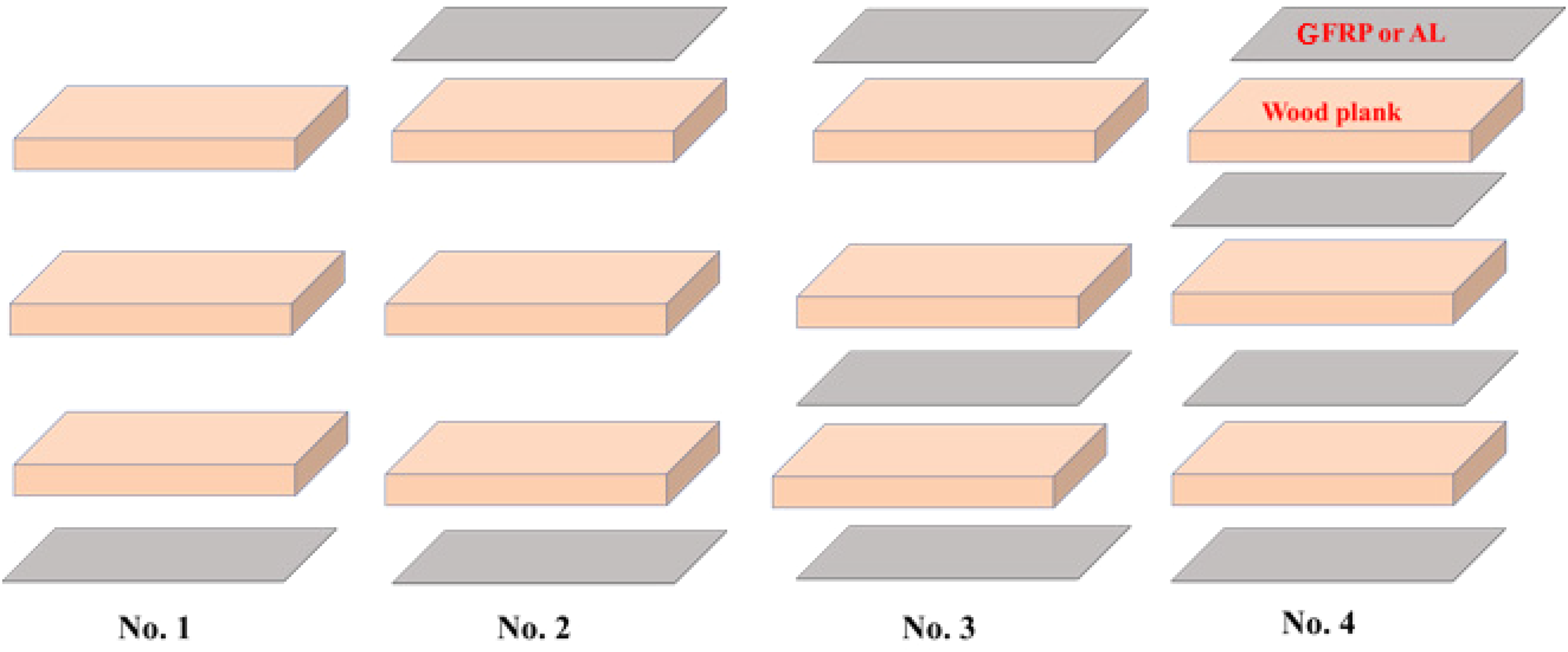
Layer arrangement of reinforcement in CLT samples. CLT: cross-laminated timber.
Bending tests were conducted on CLT samples in accordance with the ASTM D198 standard.
33
A span-to-depth ratio of 10 was considered for all specimens, and the samples were uniformly loaded across their width at the centre. The loading speed was set at 2 mm/min. Visual inspection of the failure modes of the samples was carried out until the point of failure during the bending tests. The MOR and MOE for all CLT samples were calculated using the following equations:
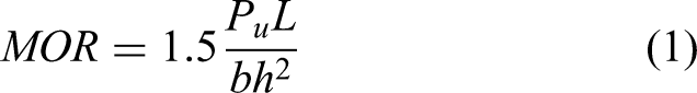
where MOR is the modulus of rupture (MPa), P is the ultimate applied force (N), L is the span of the specimens (mm), b is the width of the specimens (mm), and h is the thickness of the specimens (mm).
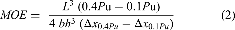
where MOE: modulus of the elasticity (MPa), L: span of the specimens (mm), 0.4Pu: load at 40% of ultimate applied load at failure point (N), 0.1Pu: load at 10% of ultimate applied load at failure point (N), b: width of the specimens (mm), h: the thickness of specimens (mm), ΔX0.4Pu: displacement at 0.4Pu (mm), and ΔX0.1Pu: displacement at 0.1Pu (mm).
Ductility was calculated by the following equation:
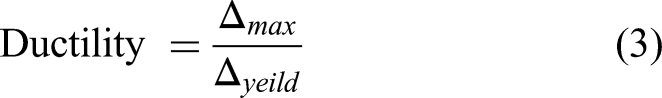
where
The data was statistically analysed using SPSS version 25. The statistical analysis of the experimental data was applied to evaluate the main and interaction effects of the components, as they were all based on a completely randomised full factorial design. This research evaluated two types of reinforcement (AL and GFRP) with four-layer arrangements of reinforcement (one, two, three, and four) as shown in Figure 1 in two panel directions of 0–90–0° (L axis) and 90–0–90° (T axis) (Total treatments = 16). Three replicates for each group were tested and compared with unreinforced control CLTs in two panel strength directions (two treatments). Therefore, 54 CLT specimens for 18 treatments were prepared for this study. Duncan's multiple range test was employed at the 95% confidence level to compare the statistical difference between the groups’ means.
Results and discussion
Statistical analysis
The impact of reinforcing material, panel direction, and layer arrangement of reinforcement on the MOR and MOE is presented in Table 1. The use of GFRP and AL reinforcement had positive effects on the MOR and MOE of CLT samples. MOR and MOE values were higher in the L panel direction of the CLTs compared to the T panel direction. Additionally, CLT samples reinforced with AL exhibited higher MOR and MOE than those reinforced with GFRP. Increasing the number of layers (AL and GFRP) in the reinforcement arrangement led to higher MOR and MOE.
MOR and MOE of reinforced and control CLT specimens.
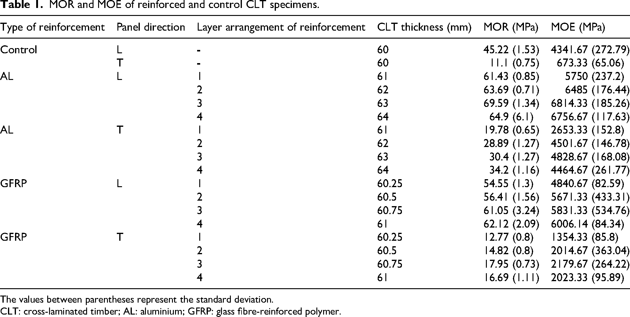
The values between parentheses represent the standard deviation.
CLT: cross-laminated timber; AL: aluminium; GFRP: glass fibre-reinforced polymer.
The higher MOR and MOE values observed in the L direction compared to the T direction are consistent with the configuration and arrangement lumbers and layers of CLT, where bending properties are generally superior along the grain (L direction) than across it (T direction). This highlights the importance of aligning the reinforcement strategy with the primary load path when designing structural CLT elements.
The maximum MOR value was observed for CLT samples reinforced with three layers of AL in the L axis (69.59 MPa), while the minimum was found for unreinforced (control) samples in the T axis (11.1 MPa). Similarly, the maximum MOE value was for CLT samples reinforced with three layers of AL in the L axis (6814.33 MPa), and the minimum was for unreinforced (control) samples in the T axis (673.33 MPa).
The results indicated that compared to the control group, reinforcing CLT samples with AL sheets increased MOR values by 53.9% in the L strength direction and 208% in the T strength direction. The corresponding increases for MOE in the L and T axes were 56.9% and 617%, respectively. Furthermore, when CLT samples were reinforced with GFRP, MOR values increased by 37.4% and 61.8% in the L and T axes, respectively. The corresponding increases for MOE in the L and T axes were 38.3% and 223.7%, respectively.
These results show that CLT samples reinforced with AL more effectively restrict deformation and improve load-carrying capacity in flexural applications.
Table 2 presents the analysis of variance for the main and interaction effects of the factors on the MOR of CLT samples. Except for the interaction effects of type of reinforcement × layer arrangement and panel direction × layer arrangement of reinforcement, all the main and interaction effects were statistically significant (p-value < 0.05). In other words, in terms of the main effects, type of reinforcement (reinforcement with AL and GFRP), panel direction (L and T), and layer arrangement of reinforcement (1, 2, 3, and 4) significantly affect MOR of CLT samples. Also, in terms of interaction (type of reinforcement × panel direction and type of reinforcement × panel direction × layer arrangement) significantly impact the MOR of CLT samples. On the other hand, the interaction of type of reinforcement × layer arrangement and panel direction × layer arrangement had no significant effect on the MOR of CLT samples.
Analysis of variance of the main and interaction effects of the type of reinforcement, panel direction, and layer arrangement of reinforcement on the MOR of the CLT.
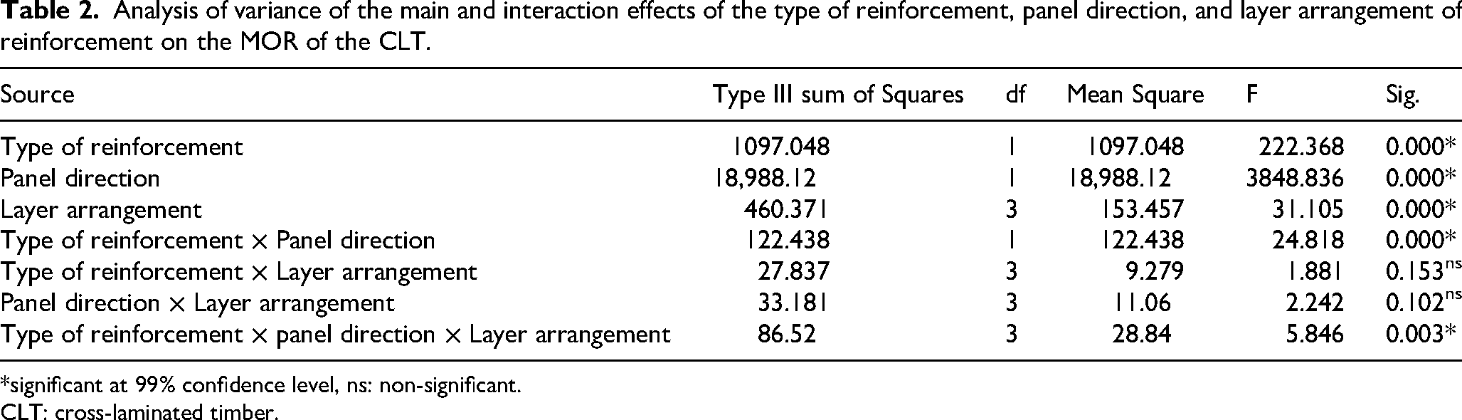
*significant at 99% confidence level, ns: non-significant.
CLT: cross-laminated timber.
The significant main effect of type of reinforcement shows that CLT samples reinforced with GFRP achieve different MOR than those with AL. This is expected since GFRP have different flexural strength compared to AL. Likewise, the significant main effect of panel direction reflects the nature of CLT: MOR of CLT samples is much stronger along the grain (L) than across it (T). Finally, the layer arrangement effect signifies that the number and orientation of layers (1–4) changes MOR in CLT samples. In this way, adding plies and changing the cross-lamination layout can enhance MOR by distributing stresses across fibres and layers. Together, these main effects confirm that material choice in terms of reinforcement, panel direction, and layer arrangement each play a key role in CLT MOR value.
Importantly, Table 2 also reveals significant interaction effects that guide how these factors combine. The type of reinforcement × panel direction interaction is significant, meaning the benefit of a given reinforcement depends on panel direction.
The significant three-way interaction (type of reinforcement × panel direction × layer arrangement) indicates that some layer configurations further modulate this effect. In contrast, the non-significant type of reinforcement × layer arrangement interaction indicates that reinforcement's effect on MOR does not change much across layer counts. Similarly, the non-significant panel direction × layer arrangement term implies that the difference between L- and T-direction MOR remains roughly constant regardless of layering, thus simplifying the design of the panel.
From a design perspective, these results highlight key structural optimisation principles. In engineered CLT systems, multiple parameters (type of reinforcement × panel direction × layer arrangement) must be tuned together to meet performance targets. The significant interactions imply that the significant interaction of the studied parameters should be considered when designing an optimal CLT system.
Similarly, Table 3 presents the analysis of variance for the main and interaction effects of the factors on the MOE of CLT samples. All the main and interaction effects were statistically significant, except for the interaction of panel direction × layer arrangement (p-value < 0.05). In other words, in terms of the main effects, type of reinforcement (reinforcement with AL and GFRP), panel direction (L and T), and layer arrangement of reinforcement (1, 2, 3, and 4) significantly affect MOE of CLT samples. Also, in terms of the interaction of (type of reinforcement × panel direction, type of reinforcement × layer arrangement, and type of reinforcement × panel direction × layer arrangement) significantly affect the MOE of CLT samples. On the other hand, the interaction of panel direction × layer arrangement had no significant effect on the MOE of CLT samples.
Analysis of variance of the main and interaction effect of the type of reinforcement, panel direction, and layer arrangement of reinforcement on the MOE of the CLT.
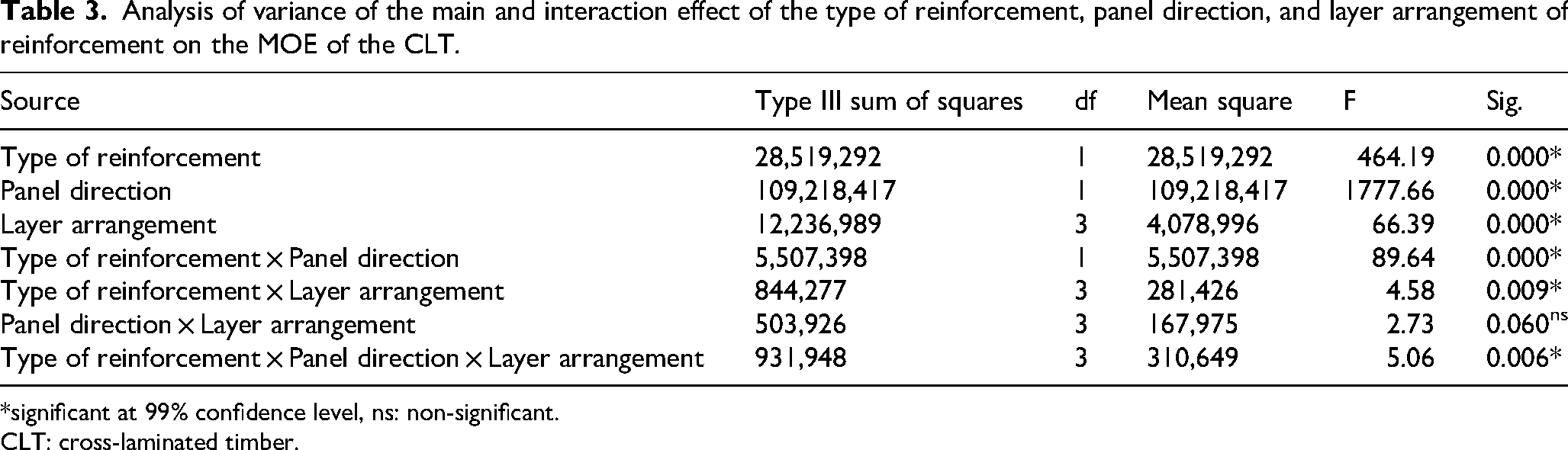
*significant at 99% confidence level, ns: non-significant.
CLT: cross-laminated timber.
The statistically significant main effects of reinforcement type, panel direction, and layer arrangement indicate the important role of each design factor in determining stiffness behaviour in CLT elements. Reinforcement type (AL or GFRP) significantly affects MOE. CLT samples reinforced with AL allowing them to better resist deformation under load. This higher stiffness translates into a more substantial increase in the overall MOE of the reinforced CLT panel, especially when the reinforcement is well-bonded and placed in high-tensile zones.
The significant effect of layer arrangement suggests that increasing the number of reinforcement layers improves the stiffness of CLT samples, likely due to increased load distribution. This finding supports current design practices where additional reinforcement or optimised lamination are used to assure the MOE of CLT systems meets specific structural demands.
The interaction effects reveal how the combined influence of two or more factors might be different from their individual effects. The significance of the type of reinforcement × panel direction interaction indicates that the reinforcement's effectiveness in enhancing MOE can be dependent on the panel direction. This may be due to the way stress is distributed across different directions.
Similarly, the significant interaction between type of reinforcement × layer arrangement indicates different reinforcement materials respond differently to variations in reinforcement quantity or distribution.
The significant three-way interaction (type of reinforcement × panel direction × layer arrangement) highlights the dependency of MOE on all three factors, suggesting that MOE optimisation in CLT cannot rely solely on adjusting a single parameter.
In contrast, the non-significant interaction between panel direction × layer arrangement suggests that variations in reinforcement layering have a similar effect on MOE regardless of panel direction. This simplification is useful in design, as it suggests that stiffness gains from layering are relatively predictable across different directional uses, thus reducing the need for separate optimisation strategies for L and T directions.
The main effects of the type of reinforcement (AL and GFRP), panel direction (L and T), and layer arrangement (1, 2, 3, and 4) on the MOR and MOE of CLT samples are detailed in Table 4. Accordingly, reinforcing with AL improved the MOR of CLT samples by 25.8% compared to those reinforced with GFRP. MOR of CLT samples in the L direction was 181.32% more than those in the T direction. In terms of layer arrangements, reinforcing with three layers significantly improved the MOR of CLT samples by 20.52% compared to those reinforced with one layer. Moreover, reinforcing with AL improved the MOE of CLT samples by 41.22%, compared to those reinforced with GFRP. MOE of CLT samples in the L direction was 100.43% more than those in the T direction. In terms of layer arrangements, reinforcing with three layers significantly improved The MOE of CLT samples by 34.63%, compared to those reinforced with one layer.
Main effects of type of reinforcement, panel direction, and layer arrangement on the MOR and MOE of CLT samples.
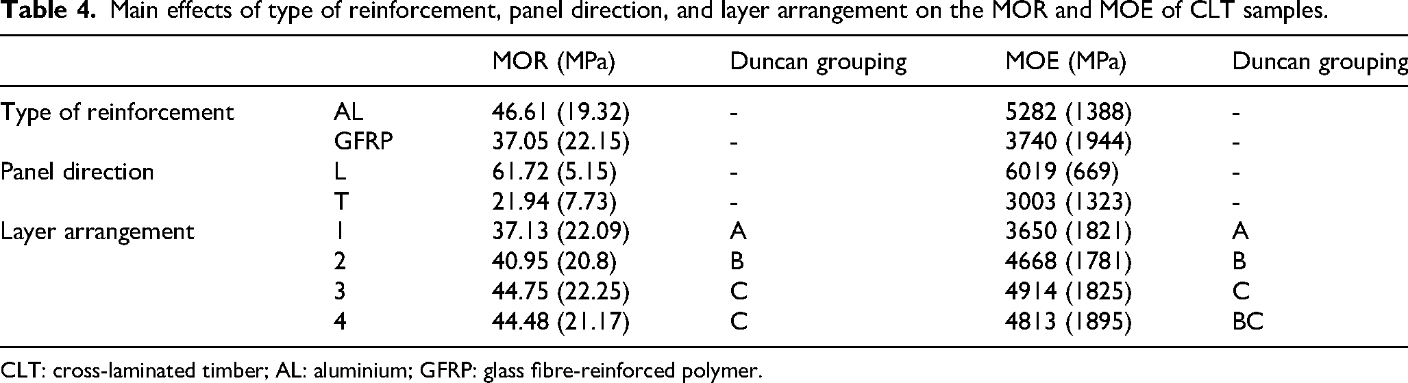
CLT: cross-laminated timber; AL: aluminium; GFRP: glass fibre-reinforced polymer.
These main effects offer valuable design guidance in selecting high-performance reinforcement materials when MOR and MOE are critical (e.g. applications subject to high bending stresses).
The interaction effects of the type of reinforcement × panel direction on the MOR and MOE of CLT samples are shown in Table 5. Accordingly, reinforced CLT samples with AL and GFRP in the L direction significantly enhanced MOR, compared to those in the T direction by 129.16% and 276.15%, respectively. Also, reinforced CLT samples with AL and GFRP in the L direction significantly enhanced MOE, compared to those in the T direction by 56.9% and 195.13%, respectively.
Interaction effects of type of reinforcement × panel direction on the MOR and MOE of CLT samples.
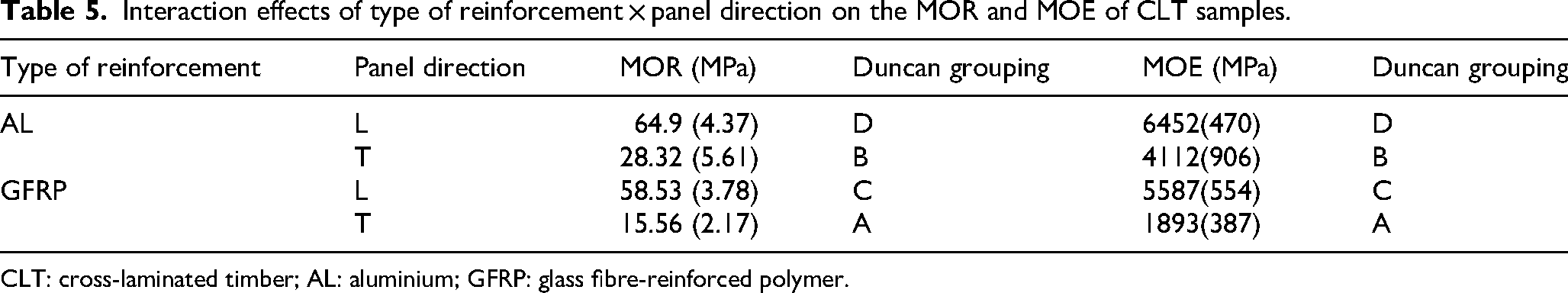
CLT: cross-laminated timber; AL: aluminium; GFRP: glass fibre-reinforced polymer.
These results support the growing body of evidence that interaction effects in hybrid CLT systems are often non-linear and material-dependent, warranting thorough analysis in the design phase. Future work might explore whether hybrid reinforcement strategies—combining AL and GFRP in a directional manner—could yield optimised performance across both MOR and MOE metrics.
The interaction effects of the type of reinforcement × layer arrangement on the MOR and MOE of CLT samples are shown in Table 6. The results indicated that reinforcing with three layers of AL improved the MOR of CLT samples (23.12%) compared to those reinforced with one layer of AL. Moreover, reinforcing with three layers of GFRP improved the MOR of CLT samples (17.34%) compared to those reinforced with one layer of GFRP. No significant difference was observed for the MOR of both types of reinforcement (AL and GFRP) with all layer arrangements (1, 2, 3, and 4). In terms of MOE, the results indicated that reinforcing with three layers of AL improved the MOE of CLT samples (38.55%) compared to those reinforced with one layer of AL. Moreover, reinforcing with four layers of GFRP improved the MOE of CLT samples (29.59%) compared to those reinforced with one layer of GFRP. No significant difference was observed for the MOE of both types of reinforcement (AL and GFRP) with 1, 2, and 3 layer arrangements.
Interaction effects of type of reinforcement × layer arrangement on the MOR and MOE of CLT samples.
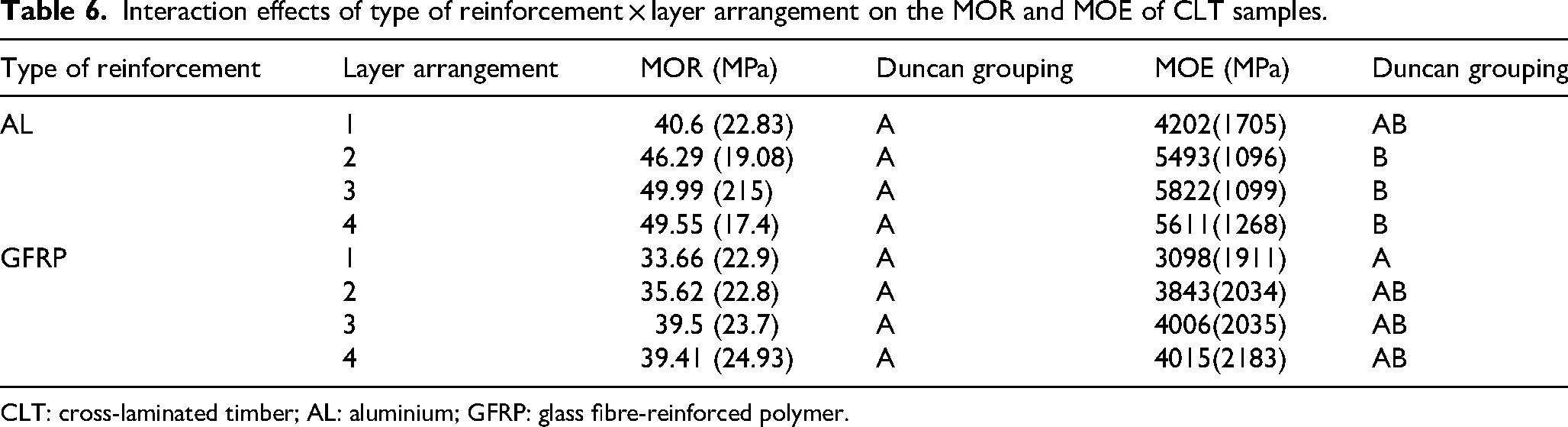
CLT: cross-laminated timber; AL: aluminium; GFRP: glass fibre-reinforced polymer.
The interaction effects between reinforcement type and layer arrangement reinforce the importance of strategic reinforcement planning in CLT design. Material selection should consider both mechanical properties and interaction behaviours, while reinforcement configuration should be optimised for efficiency rather than excess. These findings align with broader trends in engineered timber design, which increasingly prioritise performance-based optimisation over conventional empirical approaches.
The interaction effects of panel direction × layer arrangement on the MOR and MOE of CLT samples are shown in Table 7. The results indicated that in the L direction, reinforcing with three layers improved the MOR of CLT samples (12.64%) compared to those reinforced with one layer. In the T direction, reinforcing with four layers improved the MOR of CLT samples (56.51%) compared to those reinforced with one layer. No significant difference was observed in the MOR value for the CLT samples reinforced with 1, 2, 3, and 4 layer(s) of reinforcement in both L and T directions. In terms of MOE, in the L direction, reinforcing with four layers improved the MOE of CLT samples (20.5%) compared to those reinforced with one layer. However, it was not significant. In the T direction, reinforcing with three layers significantly improved the MOE of CLT samples (74.85%) compared to those reinforced with one layer.
Interaction effects of panel direction × layer arrangement on the MOR and MOE of CLT samples.
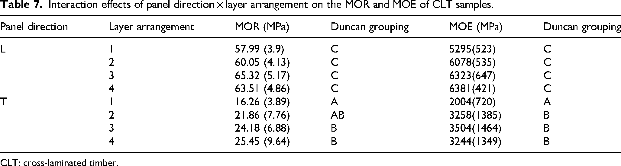
CLT: cross-laminated timber.
Finally, the interaction effects of type of reinforcement × panel direction × layer arrangement on the MOR and MOE of CLT samples are shown in Table 8. The results indicated that in the L direction, reinforcement with three layers of AL showed a significant difference compared to other groups. No significant difference was observed in the MOR value for the CLT samples reinforced with 1, 2, and 4 layer(s) of AL. Also, by increasing the reinforcement layer(s) with AL in the L direction from 1 to 3, the MOR of CLT samples increased by 13.28%. However, the same analysis in the T direction showed that reinforcement with four layers of AL showed significant improvement, compared to other groups. Also, by increasing the reinforcement layer(s) with AL in the T direction from 1 to 4, the MOR of CLT samples increased by 72.9%.
Interaction effects of type of reinforcement × panel direction × layer arrangement on the MOR and MOE of CLT samples.
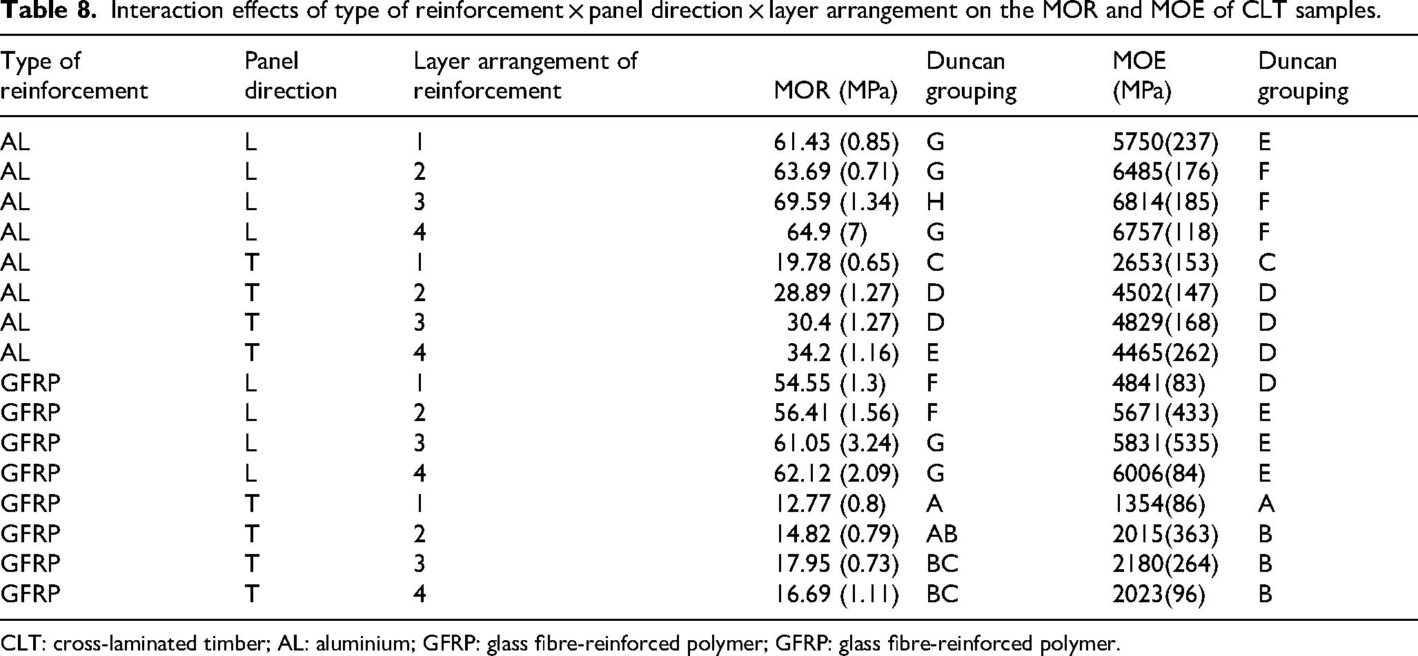
CLT: cross-laminated timber; AL: aluminium; GFRP: glass fibre-reinforced polymer; GFRP: glass fibre-reinforced polymer.
Regarding GFRP, the results indicated that in the L direction, reinforcement with three and four layers showed a significant difference, compared to one and two layer(s). Also, by increasing the reinforcement layer(s) with GFRP in the L direction from 1 to 4, the MOR of CLT samples increased by 13.87%. Also, by increasing the reinforcement GFRP layer(s) in the T direction from 1 to 3, the MOR of CLT samples increased by 40.56%. In terms of MOE, the results indicated that in the L direction, reinforcement with two, three, and four layers of AL showed a significant difference, compared to the reinforcement with one layer of AL. No significant difference was observed in the MOE value with the CLT samples reinforced with two, three, and four layers of AL. Also, by increasing the reinforcement layer(s) with AL in the L direction from 1 to 3, the MOE of CLT samples increased by 18.5%.
Similar analysis in the T direction showed that reinforcement with two, three, and four layers of AL showed a significant difference, compared to the reinforcement with one layer of AL. No significant difference was observed in the MOE value with the CLT samples reinforced with two, three, and four layers of AL. Moreover, by increasing the reinforcement layer(s) with AL in the T direction from 1 to 3, the MOE of CLT samples increased by 82.02%. Regarding GFRP, the results indicated that in the L direction, reinforcement with two, three, and four layers showed a significant difference, compared to one-layer reinforcement. However, no significant difference was observed between the reinforcement of CLT samples with two, three, and four layers of GFRP. By increasing the reinforcement layer(s) with GFRP in the L direction from 1 to 4, the MOE of CLT samples increased by 24.06%. Also, the same analysis in the T direction showed that reinforcement with two, three, and four layers of GFRP showed a significant difference, compared to the reinforcement with one layer of GFRP. However, no significant difference was observed between the reinforcement of CLT samples with two, three, and four layers of GFRP. By increasing the reinforcement layer(s) with GFRP in the T direction from 1 to 3, the MOE of CLT samples increased by 61%. This three-way interaction highlights the synergistic effects of material type, structural orientation, and reinforcement layout in determining CLT performance to achieve highly optimised timber products suitable for demanding structural applications.
Load–displacement curves
The results of the experimental load–displacement curves under the bending load for the CLT samples in the L and T axes are presented in Figures 2–4. As observed, the CLT specimens exhibited a greater load-carrying capability in the L axis compared to the T axis. This difference is attributed to the grain orientation in the outer layers, where the L direction benefits from the inherent strength of the wood fibres, consistent with the findings of Rostampour-Haftkhani and Hematabadi. 28 Reinforced samples demonstrated higher load-carrying capacity and ductility compared to unreinforced ones, as depicted in Figures 2 and 3. Additionally, CLT samples reinforced with AL exhibited greater load-carrying capacity than those reinforced with GFRP. The load–displacement curves reveal a transition from brittle to ductile behaviour with reinforcement. Unlike the sharp, sudden drops observed in unreinforced specimens at peak load (indicative of brittle fracture), the reinforced specimens displayed more gradual reductions in load post-peak. This ductile behaviour is particularly advantageous in structural applications such as flooring and diaphragms in buildings, where energy dissipation and failure warning are critical for safety. The maximum load-carrying capacities were observed for AL-4-L and AL-3-L specimens. Increasing the layer arrangement of reinforcement (AL and GFRP) from 1 to 4 resulted in higher load-carrying capacities of CLT specimens under bending load. The load–displacement curves offer valuable insights into the behaviour of CLT samples under load. Studies on the load–displacement curves revealed that wood behaved as a brittle material when subjected to bending force, failing abruptly at the highest stress level. However, in CLTs, reinforcement resulted in a ductile behaviour, as indicated by gradual failure in the reinforced samples, in contrast to the relatively abrupt failure of the unreinforced samples. This ductile behaviour is advantageous for CLT, particularly for building flooring.10,12

Load–displacement curves of control (unreinforced) CLT samples in the L and T axes. CLT: cross-laminated timber.
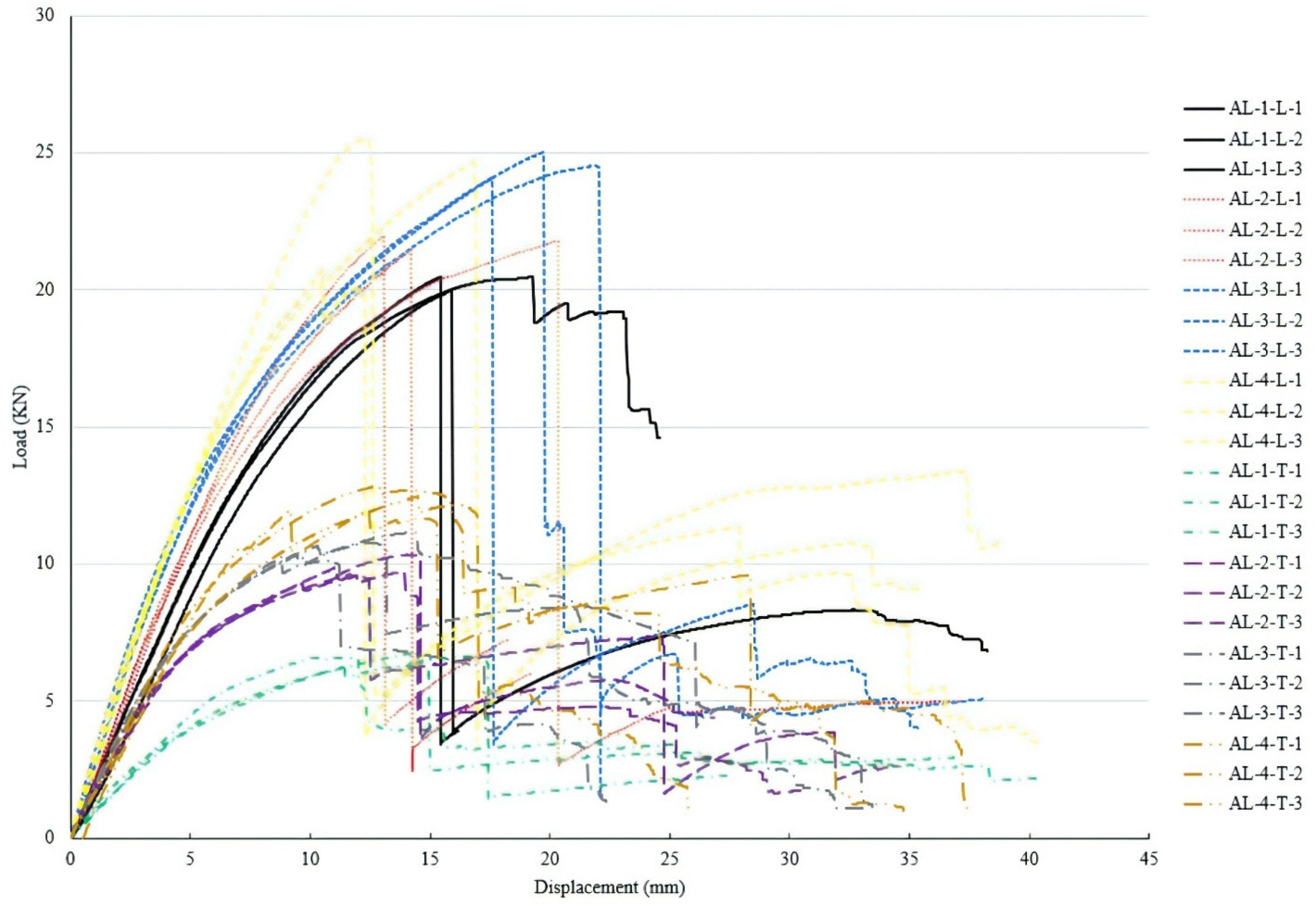
Load–displacement curves of CLT samples reinforced with AL in the L and T axes. CLT: cross-laminated timber; AL: aluminium.
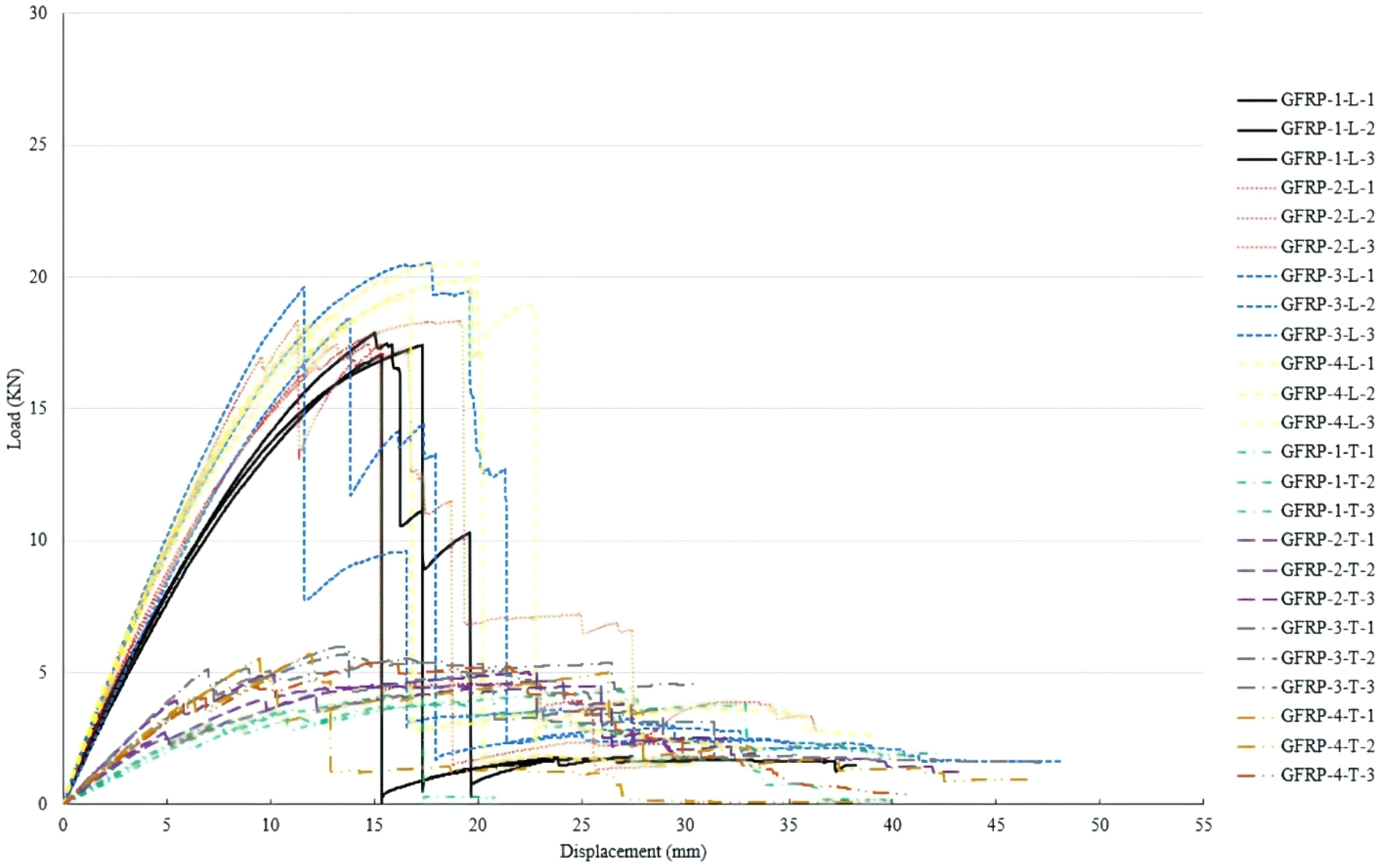
Load–displacement curves of CLT samples reinforced with GFRP in the L and T axes. CLT: cross-laminated timber; GFRP: glass fibre-reinforced polymer.
Ductility
The ductility results, illustrated in Figure 5, indicated that the CLT samples reinforced with AL sheet exhibited the highest ductility in both the L and T axes with the adding of a three-layer arrangement. For CLTs reinforced with GFRP, higher ductility was observed in the L axis with layer arrangement no. 3, and in the T axis with layer arrangement no. 2. Reinforcing with AL sheet increased ductility by 76.6% and 28% in the L and T directions, respectively, compared to the control samples. Similarly, reinforcing CLT with GFRP led to increased ductility values of 47% and 55% in the L and T directions, respectively.
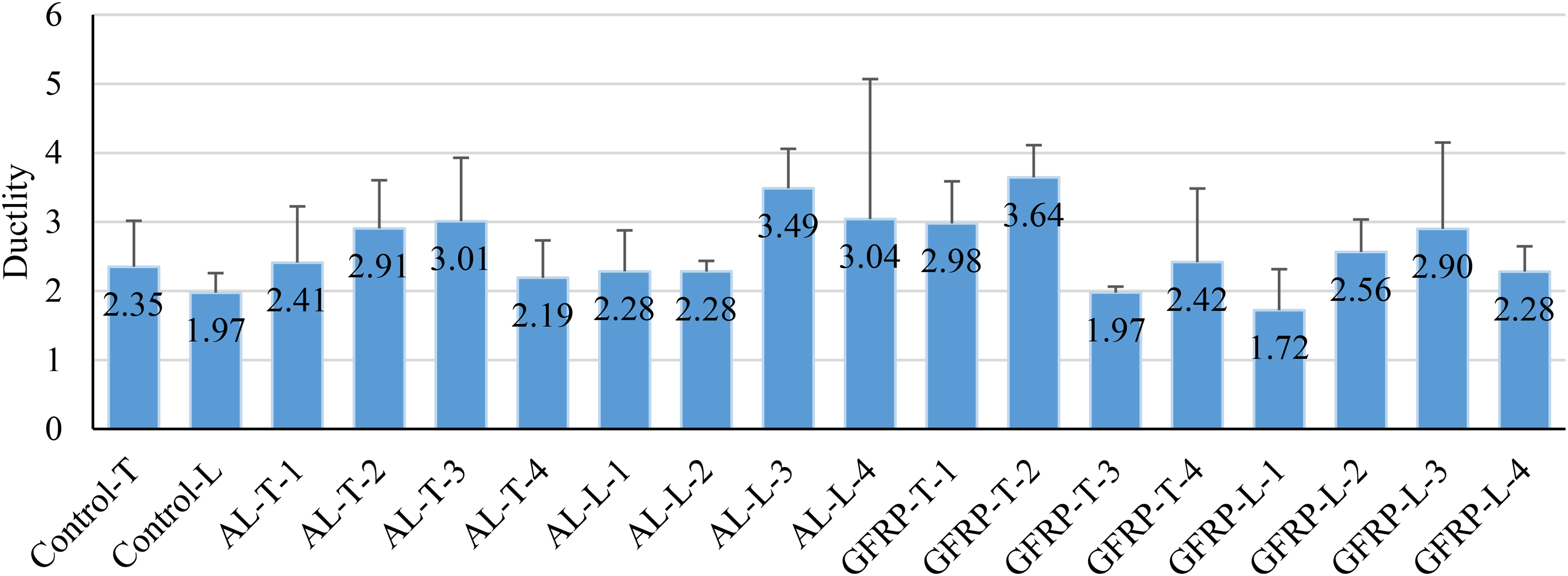
Ductility of reinforced (GFRP and AL) and unreinforced (control) CLT samples. CLT: cross-laminated timber; AL: aluminium; GFRP: glass fibre-reinforced polymer.
These results suggest that both AL and GFRP reinforcements significantly enhance the ductility of CLT panels, with AL being more effective overall. The superior performance of AL, especially in the L direction, indicates its better compatibility with timber in resisting deformation under bending. The observed variation in optimal layer numbers for GFRP also highlights the influence of reinforcement type and direction on ductility behaviour.
Failure modes
Figures 6 and 7 depict failure modes of the CLT samples in the L and T axes under the bending load. When the CLT samples were subjected to a bending load in the L axis, the layers of the bottommost surface failed in a tensile and splintering mode due to the distribution of tensile stress. In contrast, the layers of the uppermost surface fractured in a compression mode due to the distribution of compression stress. In this case, the middle layers failed with rolling shear mode along the growth rings in the earlywood area. Additionally, when the reinforced CLT panel was loaded in the L axis, delamination failure mode was observed due to the higher strength and stress distribution, specifically shear stress.
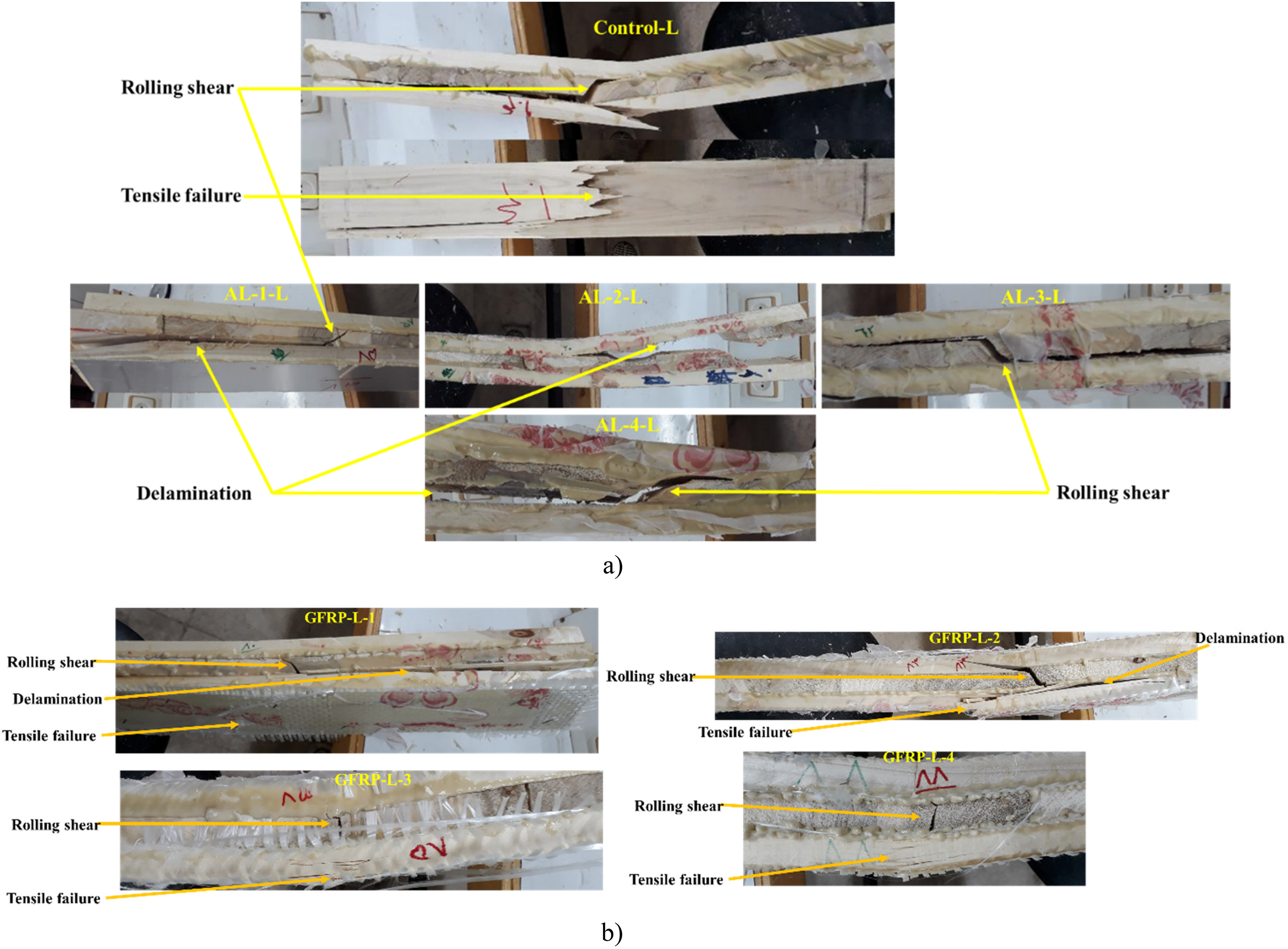
Failure forms of reinforced (AL and GFRP) and unreinforced (control) CLT samples in the L axis. (a) Failure modes of reinforced (AL) and unreinforced (control) samples; (b) failure modes of reinforced (GFRP) and unreinforced (control) samples. CLT; cross-laminated timber; AL: aluminium; GFRP: glass fibre-reinforced polymer.
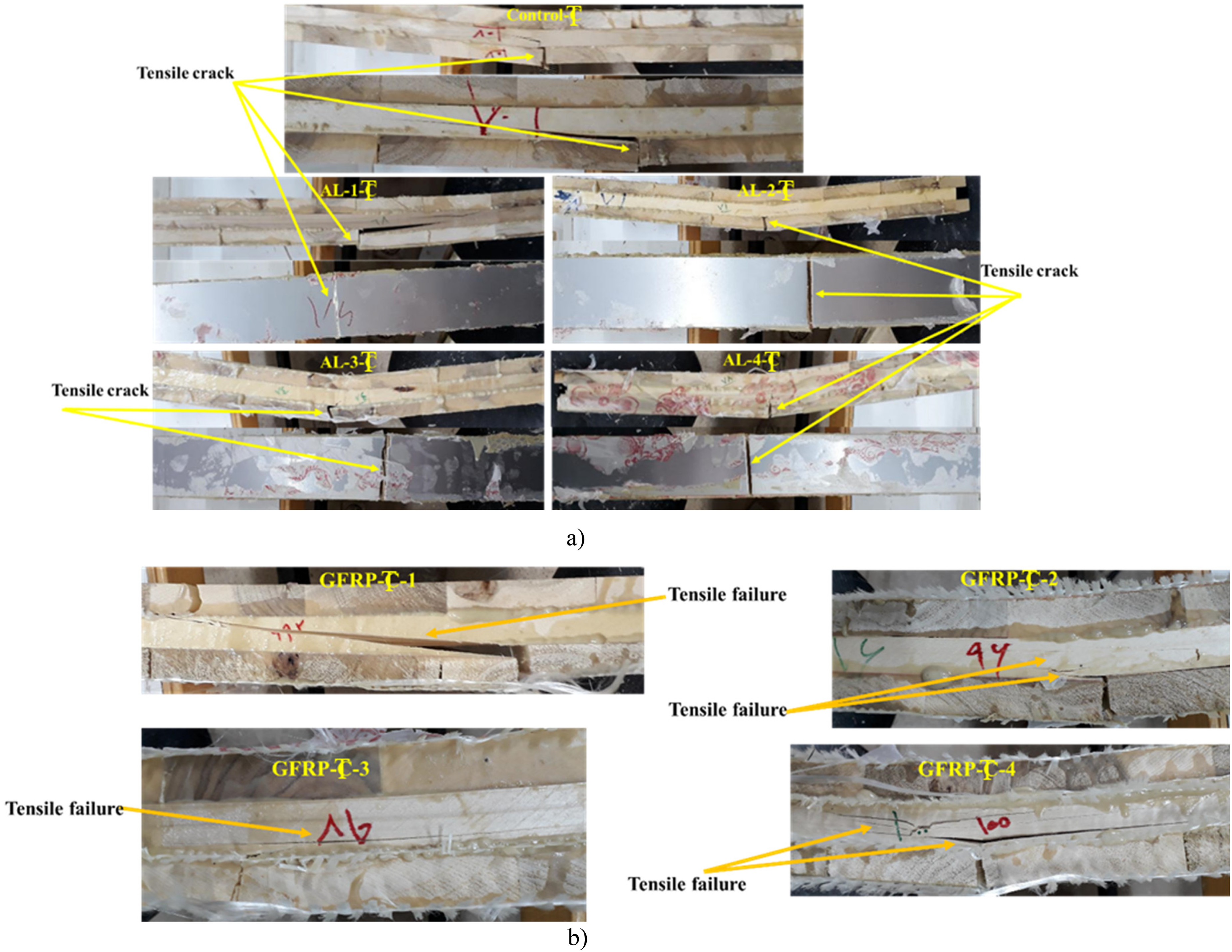
Failure forms of reinforced (AL and GFRP) and unreinforced (control) CLT samples in the T axis. (a) Failure modes of reinforced (AL) and unreinforced (control) samples; (b) failure modes of reinforced (GFRP) and unreinforced (control) samples. CLT: cross-laminated timber; AL: aluminium; GFRP: glass fibre-reinforced polymer.
However, when the CLT samples were subjected to a bending load in the T axis, they failed in tension mode due to the distribution of tension stress in the lower surface of the middle layer and in compression mode due to the distribution of compression stress in the upper surface of the middle layer. The bottommost and upmost layers of the CLT samples, which were placed transversely, failed in a brittle mode with the distribution of compression and tension stress on the surfaces. Moreover, due to the high strain of the T axis of CLTs in the surface layers, especially the bottommost layer, the reinforcing layers failed in the form of tensile cracks. The same failure modes were observed for the L and T axes of CLT specimens reinforced with GFRP.
When considering the distribution of compression, tension, and shear stress among the T section of the CLT panel under bending loading, it can be concluded that the addition of AL sheets and GFRP sheets to the CLT reduces stress concentration on the wooden layers. In reinforced CLTs, stress concentration on the wooden layers is further reduced, resulting in an increase in the final bending strength of CLTs with an increase in the number of reinforcing layers.
The effect of stress concentration with an increase in the number of reinforcing layers by changing their arrangement from one layer to four layers was observed in the failure modes of CLTs. As shown in Figures 6 and 7, the reinforcing layers failed due to stress concentration, particularly in the bottommost reinforcing layer, which is subjected to tension. Failure in the AL layer was observed in the bottommost layer of the L axis of CLT reinforced with one layer and in the T axis of all configurations.
Conclusion
This study evaluated the flexural performance of three-layer CLT samples manufactured from poplar and reinforced with AL and GFRP sheets. The results are generally aligned with prior studies on CLT reinforcement for increased mechanical properties. The experimental outcomes demonstrated that both reinforcement types (AL and GFRP) noticeably enhanced the bending performance, with AL providing greater improvements in both MOR and MOE. Reinforcement notably increased transverse direction bending performance and reducing the directional stiffness differences inherent in CLT samples. Among the reinforcement configurations, the best flexural response was achieved by specimens reinforced with two tensile-side and one compressive-side layers (configuration no.3). These reinforcements also enhanced stress transfer to the sheets and improved ductility.
This study extends current knowledge on CTL reinforcement by focusing on fast-growing hardwood CLT panels, which are underrepresented in the literature. However, the relatively small sample size limits the generalizability of these conclusions. To validate these reinforcement strategies for real-world applications, future work should include larger sample sets, alternative hardwood species, and performance assessments under long-term and seismic loading conditions.
Footnotes
Author contributions
All authors have read and approved the final version of the manuscript.
Funding
The authors received no financial support for the research, authorship, and/or publication of this article.
Declaration of conflicting interests
The authors declared no potential conflicts of interest with respect to the research, authorship, and/or publication of this article.
Data availability
Data will be available upon reasonable request from the corresponding author(s).