
Abstract
Tissue engineering has been largely confined to academic research institutions with limited success in commercial settings. To help address this issue, more work is needed to develop new automated manufacturing processes for tissue-related technologies. In this article, we describe the automation of the funnel-guide, an additive manufacturing method that uses living tissue rings as building units to form bio-tubes. We developed a method based on 96-well plates and a modified off-the-shelf liquid-handling robot to retrieve, perform real-time quality control, and transfer tissue rings to the funnel-guide. Cells seeded into 96-well plates containing specially designed agarose micromolds self-assembled and formed ring-shaped microtissues that could be retrieved using a liquid-handling robot. We characterized the effects of time, cell type, and mold geometry on the morphology of the ring-shaped microtissues to inform optimal use of the building parts. We programmed and modified an off-the-shelf liquid-handling robot to retrieve ring-shaped microtissues from the 96-well plates, and we fabricated a custom illuminated pipette to visualize each ring-shaped microtissue prior to deposit in the funnel guide. Imaging at the liquid-air interface presented challenges that were overcome by controlling lighting conditions and liquid curvature. Based on these images, we incorporated into our workflow a real-time quality control step based on visual inspection and morphological criteria to assess each ring prior to use. We used this system to fabricate bio-tubes of endothelial cells with luminal alignment.
Introduction
Living tissue-engineered products have the potential to serve as platforms for drug discovery and toxicity testing as well as implants to replace damaged or diseased tissues and organs grafts. However, successful commercialization of tissue-engineered products has been limited because of a number of factors, including challenges in manufacturing. Most tissue-engineered products are fabricated one at a time using labor-intensive methods. As outlined by the Advanced Regenerative Manufacturing Institute, automation and monitoring (quality control; QC) of tissue production are essential to commercial translation. 1 Automation can decrease cost and increase throughput and output while decreasing human error and increasing product fidelity due to the addition of QC metrics. Although automation methods exist for the culture of cells in two dimensions, there has been limited development in the automation and scale up of three-dimensional (3D) tissue-engineered products. 2
Bio-printing is a common additive manufacturing approach to fabricating tissue-engineered products. Three-dimensional macro-structures such as valves and tubes have been built drop by drop using liquid polymer scaffolds containing cells.3–9 However, bio-printing has several limitations yet to be overcome. The density of cells in the polymer scaffold is low and does not equal that of most tissues and organs. Polymerization of the scaffold occurs in air, and so the ultimate size of the printed construct is limited because cells cannot be maintained in the liquid nutrient culture medium they absolutely require. 10 Lastly, bio-printing requires the delivery of tens of thousands of small drops (manufacturing steps), and strategies to control the quality of those steps have yet to be developed.
An alternative additive manufacturing approach is the manipulation and placement of 3D microtissue building units composed of cells that have aggregated and self-assembled. These microtissues are formed without the use of a scaffold, have a high cell density comparable with normal tissue and organs, and will fuse with one another while submerged under cell culture medium.11–15 Microtissue building units are easily fabricated using hanging drop or micromolding techniques and have been formed in a variety of shapes including spheroids, rods, rings, and honeycombs, with cell numbers ranging from as few as about 500 cells per spheroid to more than 11 million cells per honeycomb. Moreover, as discrete building units of hundreds to thousands of cells, they significantly decrease the number of building steps and lend themselves to new strategies and metrics for QC.16–18
Currently available methods to manipulate microtissues include the Kenzan method; the Bio-Pick, Place and Perfuse (Bio-P3); and the Funnel-Guide. The Kenzan method uses a robotic arm to aspirate up and then precisely pierce spheroids onto a microneedle array where they fuse with one another.19–22 The Bio-P3 uses fluid suction through a membrane to grip and move honeycomb building parts through culture medium and stack them onto a build head, where the microtissue layers fuse and their lumens are perfused with culture medium during the build.23–25 The funnel-guide uses a funnel-shaped vessel to stack ring-shaped microtissues that have been added one at a time using a standard liquid-handling pipette. As the ring-shaped microtissues fall through the culture medium, the funnel-guide guides them to form a stack of living rings that fuse into a single bio-tube. 26 Major advantages of the funnel-guide are cost and simplicity of use and design. Living building parts are not gripped, nor are they pierced; they are retrieved with a pipette. Moreover, minimal accuracy and precision are required to deliver rings to the large mouth of the funnel-guide. Unlike mechanized approaches that can be limited by the accuracy, precision, and expense of their motors, the accuracy and precision of the inexpensive funnel-guide is dictated by the dimensions of its stem.
In this study, we have automated the workflow of the funnel-guide. We scaled up the production of ring-shaped tissues by using 96-well plates and modified a liquid-handling robot to retrieve the rings, one at a time, and deliver them to the funnel-guide. Prior to delivery, each ring passes a real-time QC step based on images obtained from an upward facing camera. The resulting automated workflow uses rings to build living bio-tubes layer by layer, is applicable to multiple cell types, and is an advancement toward the manufacture of 3D tissue-engineered products.
Materials and Methods
Cell Culture, Micromold Fabrication, and Formation of Ring-Shaped Microtissues
Human hepatocellular carcinoma (HepG2) cells were expanded in Eagle’s Minimum Essential Medium (EMEM; Corning Incorporated, Corning, NY) supplemented with 10% fetal bovine serum (Thermo Fisher Scientific, Waltham, MA) and 1% penicillin/streptomycin (MP Biomedicals, LLC, Santa Ana, CA). Human umbilical vein endothelial cells (HUVECs) were expanded in endothelial growth medium (EGM) with Supplement Kit (PromoCell, Heidelberg, Germany) and 1% penicillin/streptomycin (MP Biomedicals, LLC). Cultures were maintained in a 37 °C, 5% CO2 atmosphere. Cells were trypsinized, counted, and resuspended to the desired cell density for each experiment.
Agarose gels were cast from 3D Petri Dish micromolds (Microtissues, Inc., Providence, RI) as previously described. 24 Ninety-six-well agarose gels were cast from either PEEK or stainless-steel molds (Proto Labs Inc., Maple Plains, MN). Briefly, 90 µL (PEEK mold) or 80 µL (stainless-steel mold) of molten agarose was pipetted into the 96-well plate, and a drop of agarose was placed into the recesses in the mold before inverting and placing into the 96-well plate. Once the agarose solidified, the mold was removed. Gels were equilibrated in serum-free EMEM or EGM at 37 °C and 5% CO2 for 24 h prior to use. Agarose gels were made with powdered agarose (low electroendosmosis/multipurpose/molecular biology grade; Fisher BioReagents, Thermo Fisher Scientific, Waltham, MA), sterilized by autoclaving, and then dissolved in sterile water to 2% (weight/volume). 3D Petri Dish recesses were 1400 µm in diameter with a central agarose peg of 600 µm and surrounding 400 µm trough and contained 36 recesses per gel. Ninety-six-well recesses were 2200 µm in diameter with a central agarose peg of 1400 µm and a surrounding 400 µm trough. Each well contained an agarose gel with a single ring-shaped recess. Gels were seeded at a density of 50,000, 75,000, or 100,000 cells per feature or 100,000, 150,000, or 200,000 cells per 96-well feature. Cells aggregated in the micromolds and self-assembled microtissues were used 4 h after cell seeding.
Evaluation of the Morphological Changes of Tissue Rings
Tissue rings were either imaged inside agarose molds or transferred using a wide-bore pipette tip into 96-well plates with agarose-coated wells equilibrated with culture medium. Snapshot and time-lapse imaging was performed using a Zeiss Axio Observer Z1 equipped with an AxioCam MRm camera with ZEN software (Carl Zeiss Microscopy, LLC, Thornwood, NY). Side-view imaging was performed by transferring rings into a cuvette (Dynalon Corporation, Rochester, NY) filled with growth medium. Images were captured using a DinoLite digital microscope (BigC Dino-Lite, Torrance, CA). Tissue ring release from the micromold was quantified in a Kaplan-Meier curve, in which release from the mold was an event. Tissue formation only counted rings with the potential to form; mold defects were excluded from analysis. Measurements of cross-sectional area (AC) were obtained using a thresholding macro on ImageJ (National Institutes of Health, Bethesda, MD). Measurements of the ring outer diameter (DO) and lumen diameter (DL) were obtained using Zen software by taking the average of the vertical and horizontal measurement of each parameter. Thickness (T x,y ) of the rings in the x,y dimensions was calculated by

Measurements of AC, DO, DL, and T x,y were normalized to the T = 0 measurements. Height (H) measurements were taken using ImageJ (National Institutes of Health). Ring volume was calculated by

where h is the semi-minor axis of the ellipsoid cross section (

Fabrication and Use of the Funnel Guide
Funnel-guide negative replicas were fabricated as previously described. 26 Briefly, SolidWorks (Dassault Systems SolidWorks Corporation, Waltham, MA) was used to design the negative, which consisted of three chambers: a free-fall chamber, a funnel-chamber, and a stacking chamber. Free-fall and funnel-chamber dimensions remained the same at 8 mm × 8 mm and 10 mm in height, and 77° and 13 mm in height. The stacking-chamber dimensions were 1.9 mm in diameter and 10 mm in height, to accommodate the 96-well rings. The negative replicas of the funnel-guide were 3D printed by Proto Labs. Funnel-guides were then fabricated by pouring polydimethylsiloxane (PDMS) (SYLGARD 184 Silicone Elastomer Kit, Dow Chemical Company, Midland, MI) into a cuvette (Dynalon Corporation, Rochester, NY). PDMS was cured for 1 h at 100 °C and then overnight at room temperature. The funnel-guide negative replica was removed, leaving behind a void in the PDMS in the shape of the desired funnel-guide. The inside was then coated with a 3% (weight/volume) Pluronic F-68 (Sigma-Aldrich, St. Louis, MO) solution overnight.
Automated Fabrication of Bio-Tubes
To automate the fabrication of bio-tubes using the funnel-guide, an OpenTrons OT-One (Brooklyn, NY) was modified accordingly. The A-axis motor and drive assembly were unplugged and removed. The pipette was relocated to be driven by the B-axis, which was plugged into the A-axis. The z-axis was extended vertically by adding a piece of aluminum stock frame (McMaster Carr, Elmhurst, IL). The A-axis limit switch was repurposed to be the z-axis probe limit switch and was connected to the B-axis limit switch input, which was reconfigured to act as the probe. To probe the z height, the limit switch and spring steel flexures (McMaster Carr, Elmhurst, IL) were mounted on a custom pipette tip holder designed using SolidWorks (Dassault Systems SolidWorks Corporation, Waltham, MA) and 3D printed using Shapeways 3D Printing Company services (Shapeways HQ, New York, NY).
A LabVIEW (National Instruments, Austin, TX) interface was created to control the OpenTrons OT-One liquid-handling robot. At startup, the user calibrates the positions of the pipette tip, well A1 of the 96-well plates, the camera, and the funnel-guides. The user can input the number of 96-well plates and funnel-guides to be used. Located at the bottom of the LabVIEW interface is the Advanced Parameter Area, which contains the parameters that affect ring pickup from the 96-well plate. These parameters include “well height,” the height above the bottom of the well from which the robot pipettes; “federate,” the rate of aspirating and dispensing; “disp,” the baseline position for the pipette/A axis; “asp,” the distance the robot moves the pipette plunger up and down to aspirate and dispense; “extra liquid,” the additional aspiration distance to allow for reverse pipetting; “meniscus comp,” the distance to move the pipette plunger down before taking a picture for QC in order to change the curvature of the meniscus; “agitation count,” the number of times to pipette while in the well; and “speed,” the rate the pipette moves along its axes. Once calibrated and all parameters set, the user presses “Build,” which initiates the following sequence: move to pipette tip rack, move to well A1, probe z height until limit switch activated, move to well B1, pick up tissue ring, move to camera, perform QC, place tissue ring in funnel-guide or back in 96-well plate depending on the outcome of QC, move to well C1, repeat loop until all 96-well plates have been used, return home. Throughout the build process, parameters can be changed in real time by the user if needed.
Real-Time QC of Ring-Shaped Tissue-Building Parts
A camera (Blackfly S model; FLIR Systems, Inc., Wilsonville, OR) and lens (2×, 0.10 NA; Ultra Compact Objective, Edmund Optics Inc., Barrington, NJ) were mounted in an upward-facing orientation to the base of the OT-One. Our custom pipette tip holder was designed to hold a black pipette tip (TipOne for Tecan Genesis and Freedom EVO; Tecan, Männedorf, Switzerland), 1/8 inch diameter acrylic light pipe (McMaster Carr, Elmhurst, IL), and a custom printed circuit board (PCB) assembly containing a light-emitting diode (LED) and constant-current driver electronics (JLCPCB, Shenzhen, Guangdong, China) to back light the ring-shaped tissue while inside the pipette tip. During the build process, a single image of the ring in the pipette tip was taken. This image was used by our custom QC algorithm to perform real-time analysis of ring metrics. The QC algorithm uses the LabVIEW (National Instruments) “Find Circular Edges 3 VI” to identify the tissue ring. Briefly, the algorithm finds a circular edge according to the input parameters within a given region of interest (ROI). The search area is the area between two concentric rings; the algorithm generates lines between the inner and outer ring and then calculates the gradient of the image along those lines. For each line, the spot with the largest gradient becomes a hit point, which is then used to create a circle of best fit, the output of the algorithm. This analysis was conducted three times: first using the entire image as the ROI to identify the pipette tip, then using the area of the pipette tip as the ROI to locate the outer edge of the tissue ring, and finally using the outer edge as the ROI to identify the lumen of the tissue ring.
QC values were set through analysis of five plates of HUVEC 150K 4h tissue rings. QC measurements were taken using an offline LabVIEW VI, averaged, and the range set to two standard deviations from the mean. For inner and outer diameter measurements, QC LabVIEW values were converted to metric units by fitting a linear trend to a data set of QC values and measured diameter values taken in ZEN software. The determined equation was

where y represents the measured value and x represents the QC value from LabVIEW.
Evaluation of Automated Funnel-Guided Fabrication
The modified OT-One system was used to build a bio-tube composed of 30 vertically aligned HUVEC 150K 4h tissue rings. Six bio-tubes were fabricated, and success was determined through visual inspection as each tissue ring was placed into the funnel-guide. Images of the bio-tube were taken using a Pixel 3 camera (Alphabet Inc., Mountain View, CA) throughout the building process, at 5 rings high, 15 rings high, and 30 rings high. To evaluate the alignment of the tissue rings, a top-view image was taken using an Olympus SZ-PT dissecting microscope (Olympus Corporation, Shinjuku, Japan) and Pixel camera (Alphabet Inc.).
Statistical Analysis
Statistical analysis was conducted on JMP software (SAS Institute Inc., Cary, NC). The significance for AC, DO, DL, and T x,y was determined using a multivariate analysis of variance (MANOVA) with full factorial analysis for the repeated measurement of time, in which significance denotes p < 0.05. Data analyzed by MANOVA were first examined using a Shapiro-Wilk test to determine that the data came from a normal distribution. AC data were Log10 transformed to achieve normality. Ring formation as a function of peg angle and cell type was analyzed using a logistic regression in which significance denotes p < 0.05. Data were first examined using Shapiro-Wilk test to determine that the data came from a normal distribution. The significance between Kaplan-Meier survival curves was tested via pairwise Log-rank analysis (p < 0.05) with Cox’s proportional hazard regression analysis used for multivariable comparison (p < 0.005).
Results
Tissue Rings Undergo Morphological Changes
To determine the morphological changes that occur when tissue rings are self-assembled, we seeded HUVECs in agarose micromolds containing 36 ring-shaped features composed of a circular trough (400 µm wide, 1400 µm outer diameter) surrounding a central agarose peg (600 µm diameter). Cells were seeded at 5 × 10⁴, 7.5 × 10⁴, or 1 × 10⁵ cells per ring, and brightfield images were obtained every 30 min for 20 h (
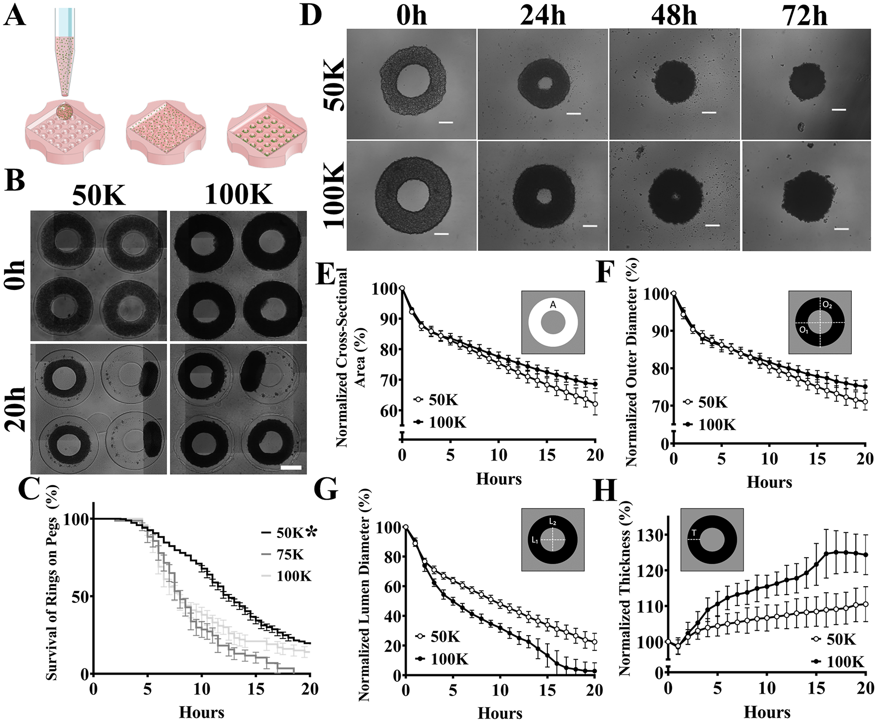
Tissue rings undergo morphological changes. Schematic of the process to form self-assembled tissue rings (
To determine the morphological changes of rings outside of the mold, HUVEC rings formed from 5 × 10⁴ and 1 × 10⁵ cells per ring were removed from the molds after 6 h of self-assembly, placed in a 96-well plate coated with agarose, and imaged over 3 d. By 72 h, the rings contracted and closed their lumens. To quantify the rate of these morphological changes, we imaged rings every 30 min for the first 20 h. From these images, we measured the cross-sectional area of the ring (Ac), outer diameter of the ring (DO), diameter of the ring’s lumen (DL), and width of the ring measured in the x, y dimensions (Txy). All values were normalized to the starting value and plotted over time. Cross-sectional area, outer diameter, and lumen diameter significantly declined over 20 h, and this decrease was significantly affected by seeding density, where 5 × 10⁴ cells per ring had a greater rate of decrease over time than 1 × 10⁵ cells per ring. Ring thickness significantly increased over time, with 1 × 10⁵ rings increasing significantly more than 5 × 10⁴ rings. There was a significant difference between seeding density and time on ring thickness, where the seeding density significantly affected the rate of change. To examine these changes more closely, we measured height (z) from side-view images (1 × 10⁵ and 5 × 10⁴ cells/ring) and compared that to width (x, y) at time 0 and 20 h (
Production of Tissue Rings in a 96-Well Plate
To adapt the agarose molds to an automated workflow, we designed a new molding system for 96-well plates so that each well has one circular feature molded in agarose that, when seeded with cells, forms one ring-shaped tissue per well (
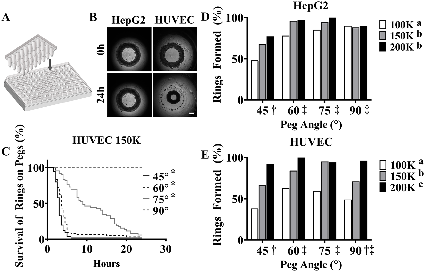
Tissue rings produced in a 96-well plate. Schematic of mold used to form one ring-shaped recess per well (
To test these angles, we seeded plates with HUVEC or HepG2 cells at 1.0, 1.5, or 2.0 × 10⁵ cells per well. Time-lapse videos showed that HUVECs (1.5 × 10⁵) formed rings that moved up and off the 60° peg by 24 h (
To determine the morphological changes of HepG2 and HUVEC rings formed using 96-well plates, tissue rings (1.5 × 10⁵ cells) were removed from the molds after 24 h of self-assembly and placed in a 96-well coated with agarose (
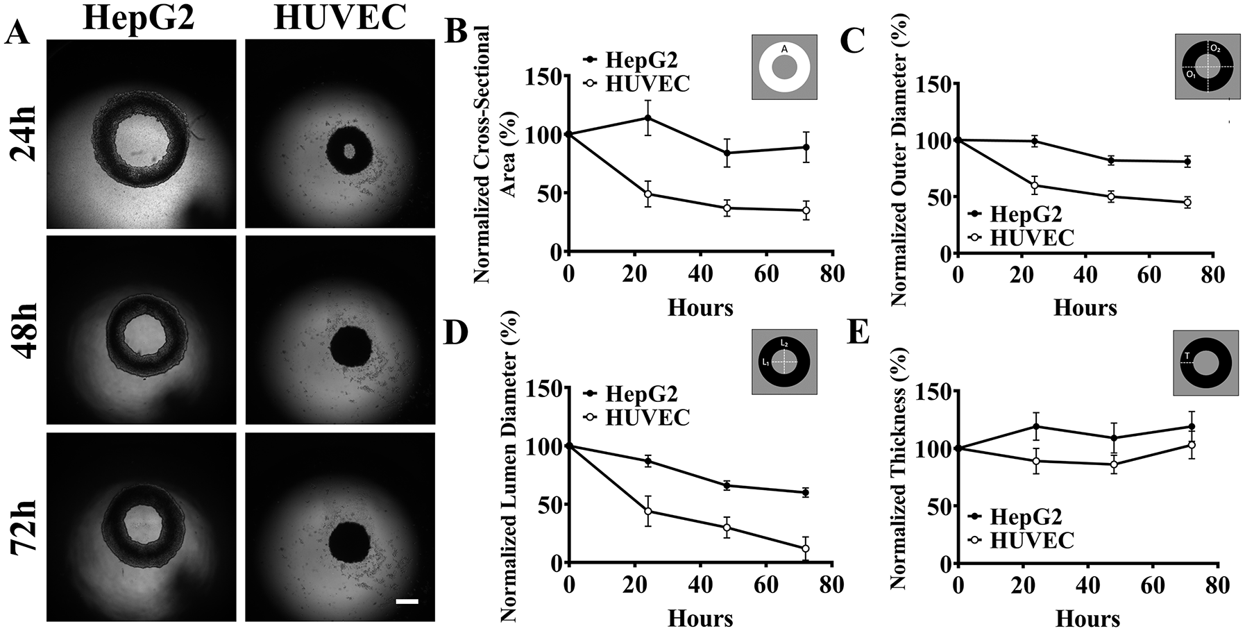
Morphological changes of tissue rings are cell type dependent. Rings were formed by seeding 1.5 × 10⁵ HepG2 cells and human umbilical vein endothelial cells (HUVECs) into 96-well plates with agarose recesses each with a 60° peg, grown for 24 h, removed, and placed on a nonadherent agarose surface. Images were acquired at 24 h, 48 h, and 72 h using brightfield microscopy (
Automated Workflow for Tissue Rings
To determine if tissue rings could be retrieved from the 96-well plates and delivered one at a time to the funnel-guide for biofabrication, we created a custom LabVIEW interface to control a liquid-handling robot as it executed an automated workflow (
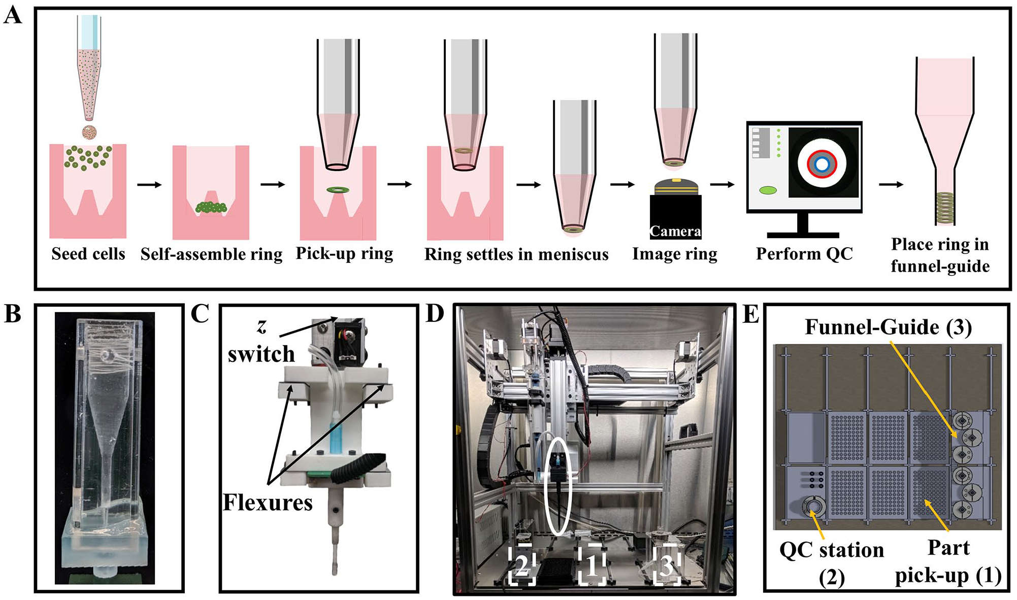
Automated workflow to use tissue rings in biofabrication. Schematic of the key steps in the workflow of a liquid-handling robot (
To acquire the QC images of the tissue rings while in the pipette, we designed a custom pipette holder and optimized the lighting conditions (
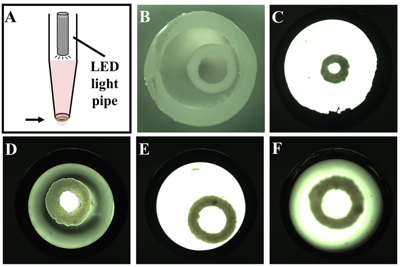
Imaging of retrieved tissue rings. Schematic of a custom-designed pipette tip holder built to house the pipette tip and the back-lighting system to take images of a tissue ring when it is positioned over the upward-facing camera. The light source is a light-emitting diode mounted to a PCB, with a potentiometer to control intensity. The light is directed to the tissue ring via a light pipe inserted into the pipette tip (
Tissue Rings Can Be Quality Controlled in Real Time
To determine if rings could be located and analyzed while inside the pipette tip, we developed a LabVIEW algorithm to process and analyze the images (
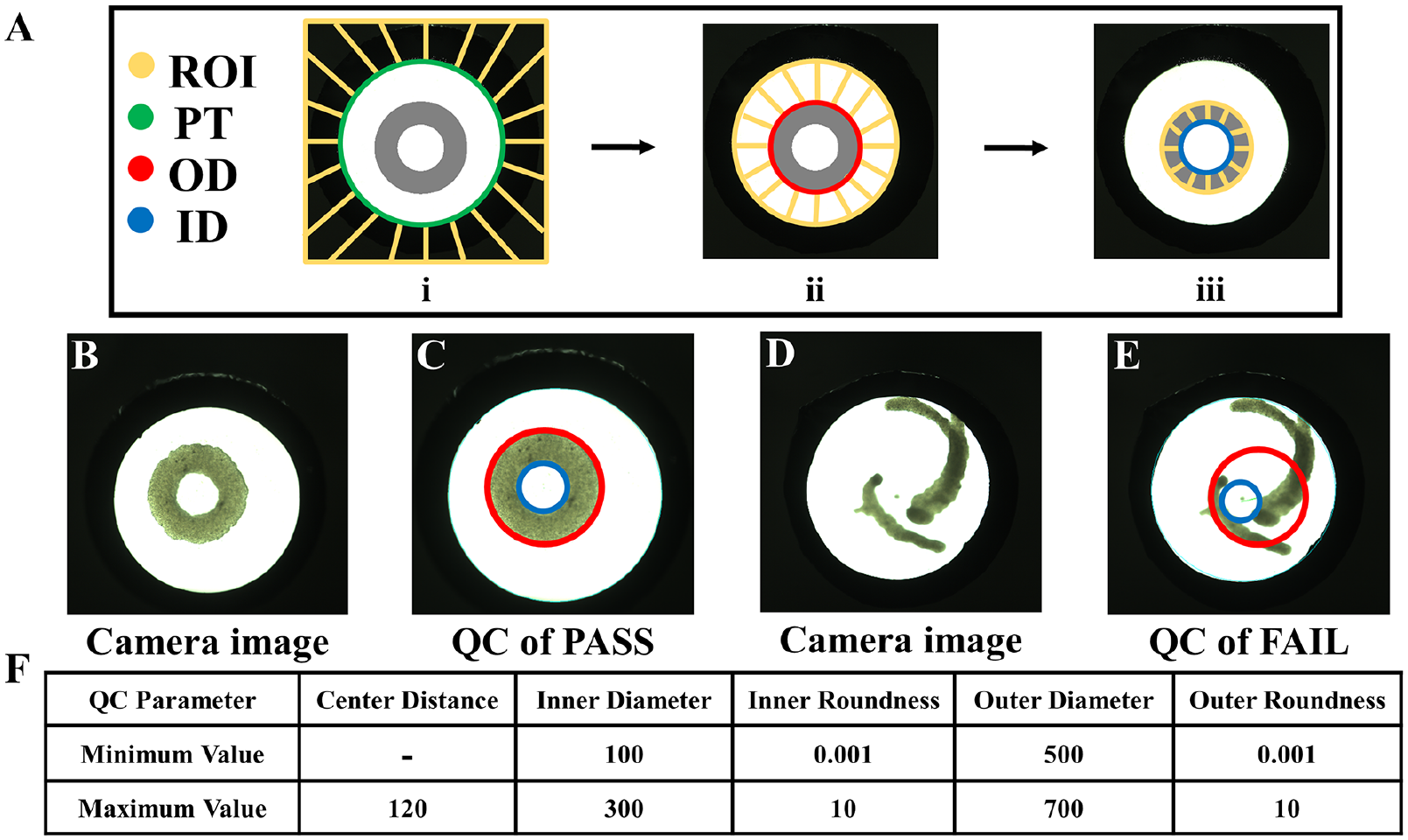
Image-based quality control (QC) of tissue rings. A custom algorithm for QC was developed to locate the outer diameter (red circle) and inner diameter (blue circle) of a tissue ring inside the pipette tip (
Bio-Tube Fabrication Can Be Automated
To determine if we could automate the funnel-guided fabrication of bio-tubes, we used the developed liquid-handling workflow with real-time QC to fabricate six bio-tubes, with each containing 30 tissue rings (
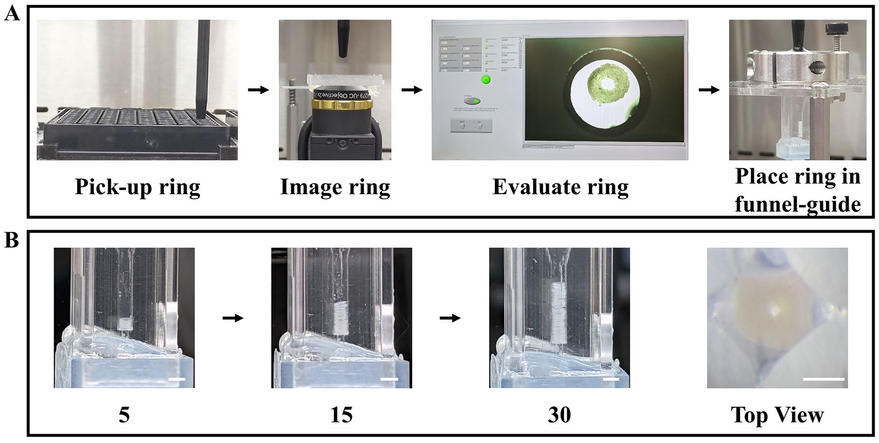
Automated fabrication of bio-tubes. Images of the key steps of the automated fabrication process (
Discussion
Since its inception nearly 40 y ago, tissue engineering has been largely confined to academic research institutions, and because of numerous challenges as well as a gap in manufacturing technologies, there has been limited success in commercial settings. To help address this issue, more work is needed to develop new automated manufacturing processes for tissue-related technologies. 1 Here, we describe the automation of the funnel-guide, an additive manufacturing method that uses tissue rings as building units to form bio-tubes. 26 All automated manufacturing processes require suitable building materials and a fundamental understanding of their inherent properties. The use of living cells in tissue engineering presents new and exciting challenges to both automation and manufacturing. Significant advances in laboratory automation have set the stage for developing new manufacturing strategies for the emerging field and industry of 3D tissue engineering. In this article, we address several of those challenges in the context of using a liquid-handling robot to automate the funnel-guide. The fundamental building unit of these bio-tubes is a ring-shaped microtissue comprised of tens of thousands of cells. We show that these building units can be produced via an easily automated process and, more importantly, that these units can be used to build bio-tubes layer by layer via automation of the funnel-guide.
To facilitate the automated production of ring-shaped building units, we designed a new micromolding system for standard 96-well plates used in laboratory automation. Each well contains a single ring-shaped recess molded in agarose. Because agarose is nonadhesive for cells, cells pipetted into the well settled into the recess, aggregated, and self-assembled around a central conical peg (1.1 mm tall) of agarose to form a ring-shaped microtissue, one per well, in less than 20 h. The resulting ring-shaped building units have an outer diameter of about 1.77 mm, an inner diameter of about 1.2 mm, a z thickness of about 275 µm, a volume of about 5.8 × 108 µm3, and are comprised of between 100,000 to 200,000 living cells. The processes by which cells aggregate and self-assemble is very complex and involves numerous cellular processes that include, but are not limited to, cell-cell adhesions, cytoskeletal contraction, cell migration/deformation, and synthesis of extracellular matrix proteins. These dynamic processes cause these living rings to undergo morphological changes that can alter their size and shape, thus presenting new challenges to the manufacture of uniform building units. Moreover, although nearly all cell types perform these complex cellular activities, there are significant differences between cell types that can further affect the fabrication of building units.
As the rings contracted around the cone, they climbed upward. The cone shape and upward motion of the rings helped facilitate their removal from the well by the fluid suction of a pipette, which is a key aspect of our automated workflow. The formation of rings as well as retrieval of rings in ANSI/SLAS 96-well plates offer numerous advantages in laboratory automation including the use of liquid-handling robots to scale up the production and retrieval of tissue rings as well as the use of existing robotic workflows and integrated equipment for cell culture, imaging, and biochemical assessments. If larger rings are needed, a similar strategy can be adapted to 48- or 24-well plates to produce rings with inner diameters of about 2.5 mm and 5 mm, respectively. So long as the ring can fit inside a wide-bore pipette tip, the retrieval can be automated using a liquid-handling robot.
The successful formation of rings and their rate of upward movement varied with cell type and was influenced by the angle of the agarose cone as well as the number of cells seeded. Both HepG2s and HUVECs required a minimum number of cells to successfully form rings. HepG2 rings climbed more slowly up the cone and were more influenced by the cone’s angle than HUVEC rings. These data are consistent with a previous study that demonstrated cell-type differences in the rate of ring movement up a cone. 27
As the rings moved up the cone, they underwent morphological changes, most notably a decrease in the diameter of their lumen. As a building unit, the lumen diameter is an important feature because it dictates the size of the lumen of the bio-tube to be built. Because the ring contacts with and contracts around the cone, the diameter of the ring’s lumen is dictated by the cone’s shape and the ring’s height on the cone, or how high the ring has moved. As with ring formation, this motion is dependent on time, cell type, number of cells seeded, and cone geometry. Seeding a well with a specified number of cells and harvesting the resulting ring at a specific time yields a building unit of defined size and shape. However, as our data also demonstrate, mold design and time of harvest are not sufficient; cell type must also be factored in when designing the process for making building units. HepG2 and HUVEC rings varied in their number of cells needed to form rings as well as the rate of ring movement up the cone.
Morphological changes to the ring building unit continued after the ring was harvested from the cone. Both HepG2 and HUVEC rings contracted and slowly decreased the diameter of their lumens over time, but this process was significantly slower (hours) than the rate of contraction while on the peg and provided more than sufficient time (minutes) to retrieve a ring building unit and transfer it to the funnel-guide before the occurrence of a significant morphological change. Interestingly contraction of HepG2 rings was significantly slower than HUVEC rings, further demonstrating cell type–specific differences.
Together, these data demonstrate that the ring building unit is a dynamic 3D structure that undergoes significant changes as it is formed by tens of thousands of living cells. We have shown that it is possible to direct and harness these changes, thereby rendering them predictable and making it possible to produce ring-shaped building units of defined size and shape. The major factors are the mold design (diameter of circular recess and the shape/angle of the central conical peg), the number of cells seeded, and the time at which the ring is retrieved from the peg. There are differences between cell types, but these differences are easily controlled by adjusting the shape/angle of the central conical peg, the number of cells seeded, and/or the time at which the ring is retrieved from the peg. Future studies will continue to evaluate the differences between rings formed from various cell types and combinations of cell types. This information will inform the construction of bio-tubes for organ systems containing multiple relevant cell types, such as a blood vessel composed of endothelial cells and smooth muscle cells. We could also investigate methods of stabilizing the contractile building parts using physical and biological inhibitors.27,28 For example, once stacked, the bio-tube could be perfused to apply radial pressure to stagnate continued morphological changes.29,30
The ability to retrieve a ring one at a time enabled us to devise a QC step based on visual inspection. When a ring was retrieved, we observed that the ring quickly settled to the liquid-air interface at the bottom of the pipette tip and could be visualized by an upward-facing camera. Acceptable images required optimal lighting as well as careful adjustment of the convex liquid surface, which created a lens effect that could distort the image. Ring intactness as well as the inner and outer diameter of the ring could be quickly identified to determine if a building part was suitable for transfer to the funnel-guide. The ability to quickly inspect building parts before use is an important addition to a robust automated manufacturing process, especially additive manufacturing. If a single defective ring were incorporated into the build of a bio-tube, it would ruin the entire build. In addition to simple morphologic criteria, other optical parameters as well as other imaging modalities could be used to assess in real time the suitability of a ring building unit.
Once a ring was deemed suitable, it was transferred by the liquid-handling robot to the funnel-guide, where simple contact between the pipette tip and the surface of the liquid in the funnel-guide released each ring. Within a maximum of 43 s, each ring had slowly settled in the funnel-guide by gravity to land on a stack of rings that fused into a bio-tube. The automated work flow for building bio-tubes had three major steps: (1) ring pick up, (2) ring imaging/evaluation, and (3) ring deposit in the funnel-guide. The cycle time between the addition of two rings to the funnel-guide was 28 s, and it took approximately 45 min to build a bio-tube containing 96 rings. Individual ring building units have a z height of about 275 µm, so all rings from a single 96-well plate could produce a stack of rings with a starting height of about 2.64 cm. Each ring is about 100,000 to 200,000 thousand cells compared to about 1000 cells in a single spheroid, which is another building unit used in additive manufacturing. Thus, compared with spheroid building units, ring building units decrease the number of manufacturing steps by a factor of about 100.
In this study, we demonstrated a proof-of-concept that we can automate funnel-guided bio-tube fabrication using a modified off-the-shelf liquid-handling robot. This provides an advantage over existing systems, such as the Kenzan and robotic assembly of vascular tissue, in which the spheroid and ring tissue parts are removed from the culture medium during the build process.18,21 In addition, our method does not require the tissue to be punctured with needles or strung through a mandrel for alignment, decreasing tissue part manipulation. Future experiments will include the development of a perfusion system connected to the base of the funnel-guide to ensure appropriate distribution of nutrients and continued improvements to the QC algorithm. Future iterations of the algorithm could incorporate an object-counting function, which would exclude images with excess cellular debris, and could incorporate elliptical best-fit features to better approximate the variety of luminal shapes.
In summary, we have modified a standard liquid-handling robot and ANSI/SLAS 96-well plates to develop an automated process for additive manufacturing of bio-tubes from ring-shaped building units. We provide the means and fundamental knowledge to scale up the production of ring-shaped building units of prescribed size and shape that are composed of more than 100,000 living cells. Our automated process includes the retrieval of rings one at a time from a 96-well plate and a new QC step in which rings are visually inspected in real time before they are transferred to the funnel-guide for bio-tube formation. This work helps demonstrate that laboratory automation can help solve the manufacturing bottleneck in the field of tissue engineering.
Supplemental Material
Supplemental_Material_for_Towards_Automated_Additive_Manufacturing_of_Living_Bio_Tubes_Using_Ring_Shaped_Building_Units_Manning_et_al – Supplemental material for Toward Automated Additive Manufacturing of Living Bio-Tubes Using Ring-Shaped Building Units
Supplemental material, Supplemental_Material_for_Towards_Automated_Additive_Manufacturing_of_Living_Bio_Tubes_Using_Ring_Shaped_Building_Units_Manning_et_al for Toward Automated Additive Manufacturing of Living Bio-Tubes Using Ring-Shaped Building Units by Kali L. Manning, Jacob Feder, Marianne Kanellias, John Murphy and Jeffrey R. Morgan in SLAS Technology
Footnotes
Acknowledgements
The authors would like to thank Joshua Manning for his assistance in capturing photographs and videos and Blanche C. Ip, PhD, and Benjamin Wilks for their assistance with statistical analysis.
Supplemental material is available online with this article.
Declaration of Conflicting Interests
The authors declared the following potential conflicts of interest with respect to the research, authorship, and/or publication of this article: Jeffery R. Morgan has an equity interest in Microtissues, Inc. This relationship has been reviewed and is managed by Brown University in accordance with its conflict of interest policies.
Funding
The authors disclosed receipt of the following financial support for the research, authorship, and/or publication of this article: This work was funded by a grant from the National Science Foundation NSF grant 1827422.
References
Supplementary Material
Please find the following supplemental material available below.
For Open Access articles published under a Creative Commons License, all supplemental material carries the same license as the article it is associated with.
For non-Open Access articles published, all supplemental material carries a non-exclusive license, and permission requests for re-use of supplemental material or any part of supplemental material shall be sent directly to the copyright owner as specified in the copyright notice associated with the article.