
Abstract
This paper presents a droplet-based immunoassay chip allowing each droplet to be positioned in a passive droplet-positioning cavern under continuous flow. In addition, the chip surface can immobilize any kind of histidine-tagged capture agents for performing simultaneous multiplex immunoassays. Distinct families of monodispersed droplets were generated since a diaphragm, which is a thin elastomeric flap film suspended from the top of the main channel, forms a double T junction for shearing the aqueous liquids by the carrier flow. These two types of monodispersed droplets traverse the main channel to the downstream detection area and enter the passive positioning caverns for further immunoassay. A layer of Ni–Co film was coated on the substrate by electrodeposition in order to immobilize the multiplex histidine-tagged capture molecules. In this study, the tumor suppressor protein p53 and the extracellular signal-related kinase 1 (ERK1) were used as the capture agents. Then, both histidine-tagged proteins p53 and ERK1 were immobilized by the Ni–Co layer in a microarray format for subsequent immunoassay and fluorescence detection. The experimental results show that the detected fluorescence intensity is proportioned to the concentration of the encapsulated content in a small droplet. This proposed droplet-based immunoassay chip can immobilize multiplex histidine-tagged proteins, irrelevant to the species of proteins, to carry out simultaneous immunoassays and allow the operation sequence to be conducted automatically through the manipulation of droplets.
Keywords
Introduction
Droplet-based microfluidics inherits all the merits of microfluidic platforms to provide an elegant solution for assays to be conducted in discrete miniscale volumes by forming droplets of an aqueous liquid in an immiscible carrier liquid.1–3 Through droplet transportation, droplet-based microfluidic systems can add new reagents to perform multistep chemical or biological reactions.4,5 Furthermore, undesirable reactions and cross-contaminations between samples can be prevented to gain increased sensitivity. To date, microfluidic droplet techniques have been implemented in the fields of chemistry and biology for research in antibody handling, 6 high-throughput screening, 7 the synthesis of nanoparticles,8,9 protein expressions,10–12 polymerase chain reaction,13–17 single-cell analysis,18–22 and so forth.
An immunoassay is a biochemical test used to detect and quantify a specific biomolecule in a solution that is usually a complex mixture of macromolecules. Relying on the ability of an analyte-specific reagent (ASR), such as an antibody, to recognize and bind the specific macromolecule, immunoassays involve multiple steps, including the addition of reagents, washing, and incubation. Conventionally, ASRs working as capture molecules are spotted on a chip surface for conducting the assay procedure. Hence, an appropriate chip surface for the immobilization of ASRs is a prerequisite for the investigation of molecular interactions. A variety of surface treatments for ASR attachment, using physical adsorption or covalent immobilization, have been developed.23,24 If the droplet microfluidic technique is preferred to carry out an immunoassay, the washing step becomes arduous to remove the residual substances since various macromolecules are encapsulated in a droplet. In addition, the immobilization of ASRs also becomes difficult and must rely on special material, such as magnetic beads. 25 To overcome such drawbacks, we present a novel droplet-positioning structure incorporated with a protein immobilization mechanism to perform multiplex immunoassays simultaneously.
The positioning of droplets for further assays is a key technique toward the development of on-chip analysis. Different trapping structures to trap droplets by means of manipulation of flow directions have been proposed.26,27 In this study, the designed trapping structure has a passive droplet-positioning feature. Under continuous flow, each droplet can be transported and positioned in a cavern at the detection area for further immobilization, incubation, and fluorescence detection. However, the immobilization of capture molecules is a prerequisite for the investigation of molecular interactions. It is especially cumbersome to immobilize multiple types of capture molecules on the same chip surface since different surface modification methods might be required. On our chip surface, a Ni–Co alloy layer fabricated by electrodeposition was used to immobilize the capture molecules. The immobilization mechanism is based on the technique of immobilized metal affinity chromatography (IMAC).28–30 Different from the reported works, the Ni–Co film developed in our previous works is an alloy type of protein chip with bimetallic elements to enhance the specific binding capability with the histidine (His).31–33 Therefore, the immobilization of different functional proteins with a histidine tag attached becomes feasible. To test the performance of this proposed droplet-based immunoassay chip, two biomaterials were adopted as examples of bioassays: tumor suppressor p53 and kinase ERK1. The tumor suppressor p53, characterized primarily to regulate gene expression as a sequence-specific transcription factor, is one of the most studied proteins. It plays a role in activating the DNA repair protein, inducing cell cycle arrest, and initiating apoptosis, to upregulate growth arrest and apoptosis-related genes in response to stress signals. Hence, tumor protein 53 serves to protect the organism from stimuli that lead to DNA damage and to prevent cancer. Moreover, the functions of kinase ERK1 include the regulation of meiosis and mitosis in differentiated cells. Growth factors, G-protein-coupled receptor ligands, carcinogens, and other stimuli can activate the ERK pathway. ERK activation influences a host of responses including proliferation, differentiation, and transcription regulation. However, different proteins with a histidine conjugate can be used since the immobilization of proteins on the Ni–Co film is through the histidine, based on the technique of IMAC and irrelevant to the species of proteins. Similarly, histidine-tagged antibodies can be used for clinical purposes in this proposed chip to measure the amount of the corresponding protein in a sample.
Materials and Methods
Biomaterials
The recombinant proteins histidine-tagged p53 (human) and histidine-tagged ERK1 (human) were purchased from Enzo Life Sciences Inc. (Lausen, Switzerland), while antibody p53 (DO-1) fluorescein isothiocyanate (FITC) and antibody ERK1 (K-23) Alexa Fluor 647 were obtained from Santa Cruz Biotechnology Inc. (Santa Cruz, CA). The original concentrations of p53 and ERK1 were 500 and 250 μg/mL, respectively. In addition, the original concentrations of antibody p53 and antibody ERK1 were 200 and 50 μg/mL, respectively. Phosphate-buffered saline (PBS) was prepared by dissolving 19.25 g of Na2HPO4 and 2 g of KH2PO4 in 1000 mL of DI water. Then, the solution was mixed into coating buffer, dilute buffer, and washing buffer, which were essential for the immunoassay experiment.
Chip Design
The droplet-based immunoassay chip is composed of five injection inlets, a main channel, two zigzag mixing channels, an immobilization and detection area, and oil-draining channels and reservoirs, as illustrated in Figure 1a . Their depths are all 200 μm. The widths of the main channel and mixing channel are 200 and 150 μm, respectively. The central inlet is designed for introducing the carrier fluid to the main channel, while the other inlets are used for the injection of reagents. The reagents injected from the inlets on the same side of the main channel will merge into the mixing channel, whose zigzag pattern forces them to mix thoroughly and rapidly. In order to generate two distinct families of monodispersed droplets containing different reagents for the sake of a microarrayed immunoassay, a 550 μm long by 70 μm wide diaphragm is designed and located at the junction of the main channel and mixing channel, 34 as shown in Figure 1b . The diaphragm consists of a thin elastomeric flap film suspended from the top of the main channel and produces a T junction for each mixing channel. The monodispersed droplets are formed at the T junction when the aqueous liquid is injected into the carrier fluid stream and sheared by the carrier flow. After passing through the diaphragm, these two types of monodispersed droplets line up in an alternating manner and continue to traverse the main channel. The downstream position of the main channel is the immobilization and detection area, and there are five cavernous structures located at each side of the main channel, as shown in Figure 1c . When a droplet approaches a cavern, it will be guided into the cavern since the carrier oil in front of the droplet disperses to the oil-draining channel and drags the droplet to enter the structure. Obviously, the designed cavern is a passive droplet-positioning structure without any moving parts to control the entrance of the cavern. Each cavern holds only a droplet for further fluorescence detection. At the bottom surface of each cavern, a layer of Ni–Co film is coated to immobilize the histidine-tagged proteins for immunoassay. However, the reagents are encapsulated by the carrier oil. The histidine-tagged proteins cannot be immobilized through affinity absorption of the Ni–Co layer. Therefore, oil-draining channels are arranged to link the caverns and the reservoirs for draining most of the carrier oil away.
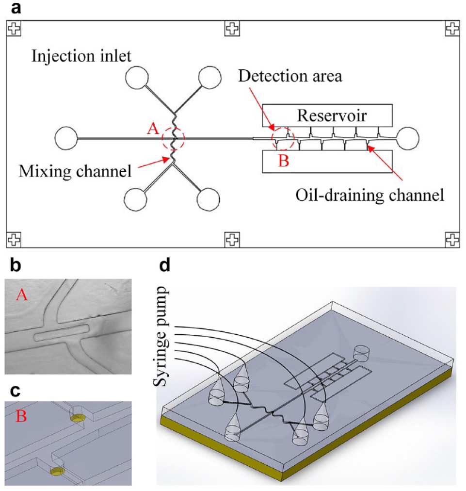
Droplet-based immunoassay chip. (a) Chip design. (b) Diaphragm suspended from the top of the main channel to form a double T junction. (c) Passive droplet-positioning structure. (d) Experimental setup.
Chip Fabrication
The droplet-based immunoassay chip was fabricated by bonding the microchannel layer to the substrate of a printed circuit board (PCB). The chip was 6.5 cm long by 3.5 cm wide. On the PCB substrate, a layer of Ni–Co film was coated by electrodeposition in order to immobilize the histidine-tagged proteins. Hence, the photoresist of PCB was completely removed such that the conducting layer, typically made of thin copper foil, can serve as a plating seed layer directly. The thickness of the deposited Ni–Co film was 2 μm. Then, the substrate was kept in a vacuum container for 24 h before proceeding to the next fabrication process. After 24 h, the PCB substrate was taken out of the vacuum container and a layer of SU-8 photoresist with a thickness of 100 µm was spin-coated on the Ni–Co film. The locations of the cavernous structures at the detection area were defined by the photolithography process. After stripping the SU-8 photoresist of these regions, the caverns were formed with the Ni–Co film exposed for immobilizing proteins.
To fabricate the microchannel layer, an SU-8 mold with the opposite pattern of all microfluidic components must be prepared first, and thus the microfluidic layer can be formed by casting polydimethylsiloxane (PDMS) in the mold. The PDMS microchannel layer was left to cure at 95 °C in an oven for 1.5 h. Afterward, it was carefully peeled from the SU-8 mold. To bond the PDMS layer to the PCB substrate, oxygen plasma treatment was adopted in this study to modify the surfaces of both the PDMS layer and the PCB substrate. Then, the PDMS layer was placed on the PCB substrate and the chip was heated in a 95 °C hot circulator oven for 30 min to complete the bonding process.
Bioassays
Due to the purchase of biomaterials, histidine-tagged proteins p53 and ERK1 played the roles of capture agents, while antibody p53 and antibody ERK1 were the analyte molecules in this study. For clinical bioassays, however, histidine-tagged antibodies can be used as the capture agents to detect their corresponding proteins.
Two groups of bioassays were carried out. The first group was designed to examine the immobilization ability of Ni–Co film to different concentrations of histidine-tagged proteins. The second group was arranged to investigate the possibility of this droplet-based immunoassay chip detecting a low abundance of antibody in the sample. In both experiments, antibody p53 and antibody ERK1 were mixed together to mimic the phenomenon that a sample usually contains multiplex analyte molecules. Thus, histidine-tagged p53 and antibody mixture were injected into the inlets on the same side. On the other hand, histidine-tagged ERK1 and antibody mixture were injected into the other inlets. As shown in Figure 1d , a KDS Legato 270 programmable syringe pump (KD Scientific Inc., Holliston, MA) was utilized to manipulate these fluids simultaneously with the same flow rates, that is, 180 μL/h. Thus, two distinct families of monodispersed droplets were generated in an alternating manner. After the droplets were positioned in the cavernous structures at the detection area and most of carrier oil was drained, the PDMS microchannel layer was carefully peeled off for further incubation and fluorescence detection. Three-hour baking in a 37 °C hot circulator oven was carried out. This step can remove the thin layer of carrier oil that still encapsulates the droplet. Moreover, incubation and immobilization on a Ni–Co surface can be accomplished simultaneously. Next, the immunoassay chip was washed with washing buffer (PBS Tween-20) three times for 1 min per wash in order to remove the residual but not immobilized proteins. A dehydration bake in a 37 °C oven for 15 min was performed again to dry the chip surface. Then, a fluorescence microscope (Eclipse 80i, Nikon, Tokyo, Japan) was used to acquire high-resolution fluorescence micrographs and these images were analyzed using NIS-Elements software. Quantitative data evaluation was done by MATLAB (MathWorks, Natick, MA).
Results and Discussion
Mixing Effect of Zigzag Mixing Channel
In a straight microchannel, two fluids flowing alongside each other retain parallel layers due to the low Reynolds number and can mix only by diffusion. To examine the mixing effect of the zigzag microchannel, white dye and red dye solutions were used as the materials for the mixing test. Both dye solutions were injected into the channel and driven by a syringe pump. The image of flow was captured and analyzed using MATLAB software to investigate the mixing phenomenon.
We divided the mixing channel into three sections and picked five locations for each section for statistical study. In the first section, the average grayscales for both dye solutions were 121.5 and 70.1, respectively. As shown in Figure 2a , these two dye solutions were separated and obviously not mixed yet. A certain degree of mixing begins in the middle section of the mixing channel and the interface of both dye solutions becomes blurred, as shown in Figure 2b . Thorough mixing can be observed in the final section of the mixing channel, as shown in Figure 2c . This result was verified by the average grayscale to be 100.6, which lies in between those of the two original grayscales. The change of grayscales in the mixing channel demonstrates that the zigzag pattern accomplished a thorough mixing effect for our experiments.
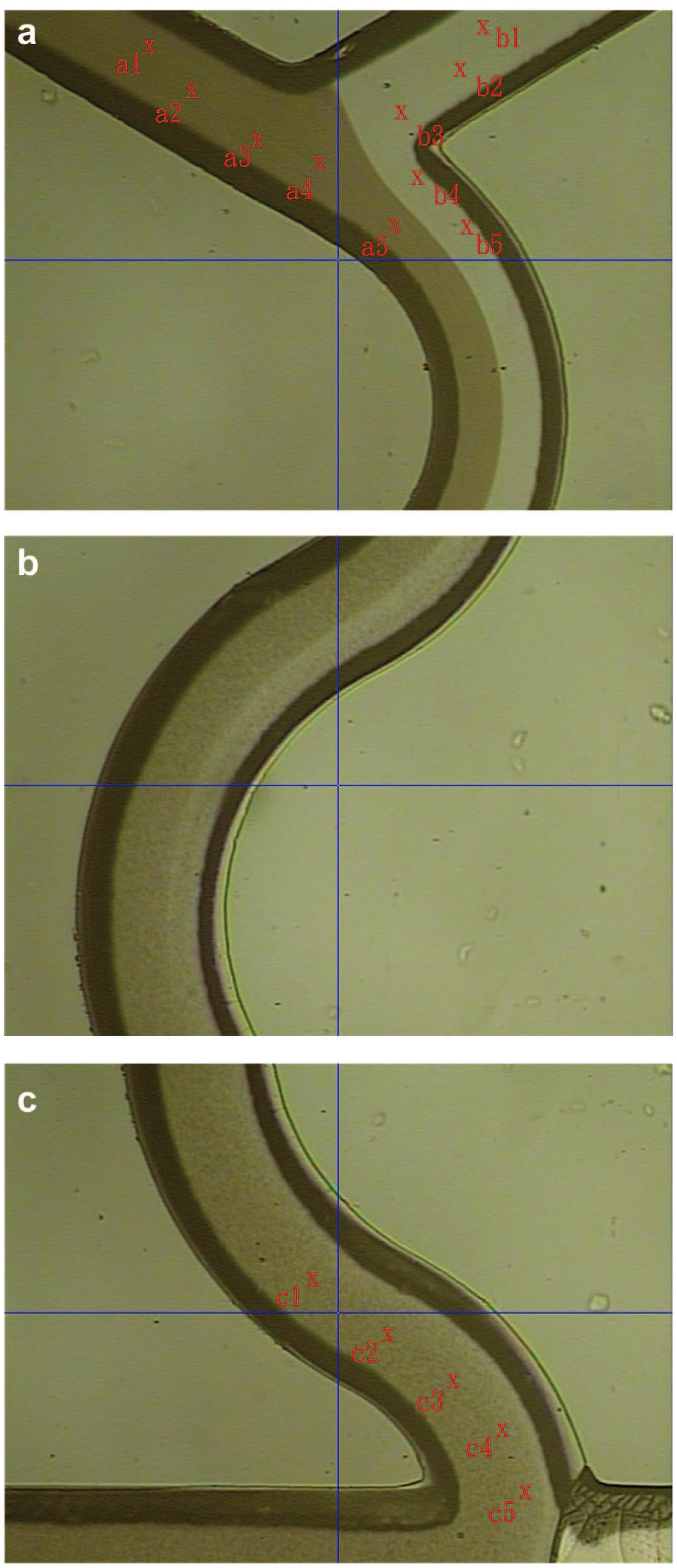
Mixing effect in the mixing channel. (a) First section. These two dye solutions are separated. (b) Middle section. The interface of the dye solutions becomes blurred due to mixing. (c) Final section. Thorough mixing is achieved.
Influence of Diaphragm upon the Droplet Formation
The purpose of the diaphragm is to segregate two solutions converging toward the main channel so that two distinct families of monodispersed droplets can be generated. Two dyed solutions were used for observing the phenomenon of droplet generation. As shown in Figure 3 , two families of dyed water-in-oil droplets were generated in turn and aligned in the main channel. However, a series of two or three droplets were formed from one side of the diaphragm. It was not a one-to-one alternating droplet formation. Our inference is that the structure of the diaphragm is the key reason. Since the diaphragm is a thin elastomeric flap film suspended from the top of the main channel, its bottom is not firmly fixed to the substrate. Although the reagents were simultaneously injected and driven by the syringe pump with the same flow rate, the pressures applied on both sides of the diaphragm might not have been identical. A slight pressure difference results in a tiny swing of the diaphragm. Thus, two distinct families of monodispersed droplets were not generated in a one-to-one alternating manner. If the two T junctions lie at symmetric locations, the pressure difference might push the diaphragm toward one of the junctions. It affects the droplet generation from that T junction until the accumulated pressure pushes the diaphragm back. Thus, it was observed that the two families of droplets, with a series of four to six droplets as a cluster, took turns entering the main channel. In this study, the positions of two T junctions are shifted in asymmetric format. This design improves the phenomenon of droplet generation.
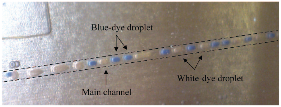
By means of a diaphragm, two families of dyed water-in-oil droplets were generated and aligned in the main channel.
Influence of Cavernous Structure upon the Droplet Positioning
The function of every cavernous structure at the downstream position of the main channel is to hold a droplet for further incubation and fluorescence detection. It is a passive droplet-positioning structure without any moving parts to control the flow of droplets. The droplet can be dragged into the cavernous structure since a portion of the carrier fluid flows toward the oil-draining channel and guides the droplet into the cavern. Once a cavern is occupied, the branch flow of carrier fluid decreases and thus the dragging force reduces. However, the dragging of droplets is still inevitable. To prevent droplet fusion from occurring in a cavern, a chamfered side of the cavernous structure was designed, as shown in Figure 4a , to allow all droplets lining up in the main channel to pass through an occupied cavern easily. Without the design of a chamfered side, the corner of the cavern might block the path of a dragged droplet back to the main channel so that droplet fusion occurs, as shown in Figure 4b . Obviously, an appropriate branch flow of carrier fluid toward the oil-draining channel and the design of a chamfered side at the cavernous structure influence the droplet positioning. As shown in Figure 4c , all droplets can pass through an occupied cavern if the design of a chamfered side is used. Moreover, Figure 4d shows that two distinct families of droplets were generated, and every droplet entered a vacant cavern without fusion.
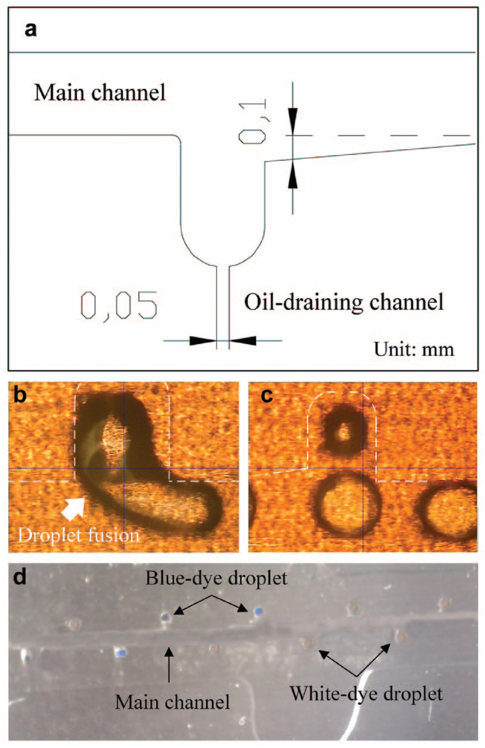
Passive droplet-positioning structure. (a) Design of a chamfered side of the cavernous structure. (b) Without the design of a chamfered side, droplet fusion occurs. (c) Droplet flow behavior with the chamfered side at the cavernous structure. (d) Droplet positioned at a cavern without fusion.
Immobilization Ability of Ni–Co Layer
This group of experiments was designed to examine the ability of the Ni–Co layer to immobilize multiplex histidine-tagged proteins from the droplets, based on the IMAC principle. Histidine-tagged protein functions as a capture agent in this study to interact with its corresponding antibody due to protein–antibody binding specificity. The immobilization of capture agents is a prerequisite for the investigation of molecular interactions.
In this group of experiments, a series of dilution gradients of histidine-tagged proteins were designed: 100×, 200×, 300×, 400×, and 500× dilution. That is, the concentrations of p53 and ERK1 under 100× dilution, for example, were 5 and 2.5 μg/mL, respectively. Moreover, both antibodies were 100× diluted. That is, the concentrations of antibody p53 and antibody ERK1 were 2 and 0.5 μg/mL, respectively. After the aforementioned bioassay procedure, fluorescence images were taken using a fluorescence microscope
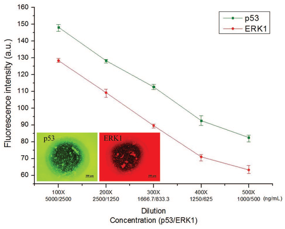
Immobilization ability of the Ni–Co layer. Both histidine-tagged p53 and ERK1 can be immobilized on the Ni–Co layer simultaneously. The mechanism to immobilize the proteins is through the histidine and is irrelevant to the species of proteins. For different concentrations of histidine-tagged proteins, the Ni–Co layer possesses a reliable immobilization ability.
Detection of Low Abundance of Antibody
Since this proposed droplet-based immunoassay chip had the ability to reliably immobilize the capture agents, the detection performance of a low abundance of antibody (the measurand) was studied. In this experiment, the concentrations of both histidine-tagged protein solutions were kept constant at 5 and 2.5 μg/mL (100× dilution), respectively. On the contrary, both antibodies were diluted to different concentrations, that is, using 100×, 200×, 300×, 400×, and 500× dilutions. Thus, the concentrations of antibody p53 and antibody ERK1 under the 100× dilution, for instance, were 2 and 0.5 μg/mL, respectively.
In a droplet, the concentration of histidine-tagged protein is greater than that of antibodies. Hence, the detected fluorescence intensity is related to the amount of antibody interacted with the protein. The experimental result shows that a higher concentration of antibody results in a stronger fluorescence intensity, as shown in
Figure 6
. For both p53 and ERK1, the relationship between the antibody concentrations and their corresponding fluorescence intensities is linear. This result indicates that the step of incubation and immobilization, performed simultaneously in our bioassay procedure, was carried out well. Furthermore, Ni–Co film has
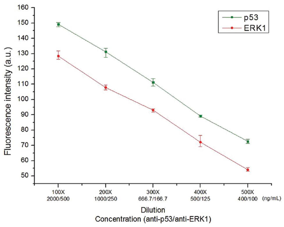
Detection of low abundance of antibody. Ni–Co film has a specific binding capability with histidine. The residual antibody (e.g., antibody ERK1 cannot interact with p53) can be completely removed during the washing step. The detected fluorescence intensity is linearly proportional to the amount of antibody that interacts with the protein.
Conclusions
Immunoassay is a crucial bioassay to measure the presence or concentration of a molecule. In this study, this proposed droplet-based chip has four features. First, it can perform simultaneous multiplex immunoassays. By means of a diaphragm, we demonstrated that two distinct families of monodispersed droplets were generated in water-in-oil emulsions working as microreactors, allowing the two distinct droplet contents to be delivered without cross-contamination. Second, a passive droplet-positioning cavern held only a droplet without fusion. No built-in active valve or external actuation apparatus is required. Chip fabrication is simple. Third, the Ni–Co alloy film can immobilize any kind of histidine-tagged capture agents based on the principle of IMAC. Since the immobilization of capture agents on the Ni–Co film is through the histidine, surface modification is no longer required. Moreover, our experiments show that the immobilization ability of Ni–Co film is satisfactory for a wide concentration range of histidine-tagged capture agents. Fourth, the droplet-based chip allows the sequence of immunoassay operations to be controlled through the manipulation of the microfluids. In addition, incubation and immobilization on the surface of Ni–Co can be accomplished simultaneously. Thus, this chip has potential applications in developing effective therapies or potential new drugs for the treatment of disease.
Footnotes
Declaration of Conflicting Interests
The authors declared no potential conflicts of interest with respect to the research, authorship, and/or publication of this article.
Funding
The authors received no financial support for the research, authorship, and/or publication of this article.