
Abstract
This paper presents a novel design of a capillary stop valve with a chamfered side that can be used as a flow regulator to hold an injected microfluid in the valve position in a capillary force-driven microfluidic device. Biochemical analysis can be conducted if the chamfer-type valves are placed at strategic positions according to the test protocol. Hence, the stored reagent can be dragged out of the valve for further reaction when the specimen passes through. However, countercurrent phenomena were observed in the commonly used T-type capillary stop valve (without the chamfered side). In blood typing tests, the countercurrent led to incomplete dragging and the fluid stopped flowing at the complicated mixing channel; thus, the blood typing reaction was attenuated. On the contrary, the chamfer-type valve reduced the countercurrent phenomena and ameliorated the blood typing reaction. Consequently, agglutination results can be easily discriminated from nonagglutination cases.
Introduction
Microfluidic systems possess many advantages, including a smaller consumption volume of reagents, shorter reaction time, and parallel operations in a single chip. They have been successfully implemented in sophisticated chemical and biological analyses for decades. The entire complicated laboratory operations can be converted in a microfluidic manner into the miniaturized and disposable chips. Hence, biomedical analyses are accomplished at the microscale. In recent years, diverse applications of biochemical analysis procedures, such as immunoassays,1–3 PCRs,4–6 and clinical diagnostics,7,8 have been reported.
Microfluidic control is a crucial design consideration for microfluidic devices, which may consist of microchannels, micropumps, microvalves, and micromixers. Through the manipulation of microfluids, reagents and samples can be transported in the microchannels for the purposes of dilution, particle separation, mixing, and incubation. Microvalves are essential and important elements in a microfluidic system, and their functions can be classified into a check valve, which allows microfluid to pass only in one direction; a stop valve, which completely stops the flow of microfluid through a microchannel; and a digital valve, which has an initial state that is normally open or closed. In addition, microvalves can be grouped into passive and active categories from the point of view of valve actuation. Active microvalves employ external energy, such as pneumatic, 9 electrical,10–12 thermal,13–15 or magnetic force,16,17 to control the action of the valves. Contrarily, passive microvalves do not rely on external energy for valve actuation. Most passive check valves are designed to respond to environmental stimuli, including pH or specific chemicals, 18 to cause the valve material to expand or shrink. Regarding passive stop valves, a sudden change of the wetting properties or geometrical structures induces the flow of microfluid to stop at the valve. The capillary stop valve is a common type of passive stop valve19–21 that prevents any further flow based on the capillary pressure barrier that develops when the cross section of a microchannel changes abruptly. The capillary stop valve is of particular interest due to its advantages of simple geometrical structures and adaptation to different fluids. Moreover, it can be used as an effective flow regulator to hold the injected microfluid in the valve position and can be easily integrated into a microfluidic system.
The driving of microfluids usually relies on either the syringe pump or the on-chip built-in micropump. However, a microfluidic device with capillary force driving is an elegant solution to achieve a portable system.22,23 Hence, the integration of a capillary force-driven microfluidic device with a capillary stop valve allows us to design a miniaturized system suitable for biochemical analysis if the valves are placed at strategic positions according to the test protocol to hold the required reagents. Nevertheless, the performance of a capillary stop valve still deserves to be investigated. In this study, a chamfer-type capillary stop valve is presented. This passive valve device is used in a capillary force-driven microfluidic network for flow control. To test the performance of this proposed chamfer-type capillary stop valve, a portable and disposable chip was designed for blood type testing.
Blood transfusion is a medical treatment to replace lost blood components. Before a transfusion, blood typing is a critical test to ensure the serological compatibility of a donor and a recipient. 24 Incompatible red blood cells (RBCs) in transfusion, that is, mistyping of the ABO blood group, might result in intravascular hemolysis, renal failure and shock, and even the recipient’s death. The manual polybrene (MP) technique for blood typing is operated using a 96-well microplate, which is widely adopted in Asia, takes about 10 min, and requires a 200 μL blood sample. However, this proposed blood typing chip, as based on the MP protocol, allows us to use minute amounts of blood samples and reagents. As no flow manipulation apparatus is required, it provides great potential for blood typing in emergency situations.
Materials and Methods
Chip Design
This microfluidic chip was designed to demostrate the function of the chamfer-type capillary stop valve in conjunction with a fluid driven by capillary force. The channel pattern can be altered based on the applications. In this study, the chip comprises one injection inlet, four reagent reservoirs, and a detection chamber. A main channel connects the injection inlet and the detection chamber. The width of the main channel is 200 μm. Four reagent reservoirs link to the main channel through the capillary stop valves, as illustrated in Figure 1a , and their depths are all 200 μm. The geometry of the capillary stop valve has an abrupt reduction in the width of its channel cross section. When a reagent is introduced in the reservoir, it is syphoned into the neck region and abruptly stops at the outer neck edge. Therefore, the reagent is kept in the reservoir by the capillary stop valve. Once a specimen is introduced into the injection inlet, the capillary force will drive it to traverse the main channel. When the specimen passes through the capillary stop valve, it drags the reagent out of the reservoir. Due to the location arrangement of the capillary stop valves, all reagents can be added in a specific sequence according to the test protocol without the assistance of any apparatus. In addition, the zigzag mixing channels allow the specimen and the reagents to be thoroughly and rapidly mixed.
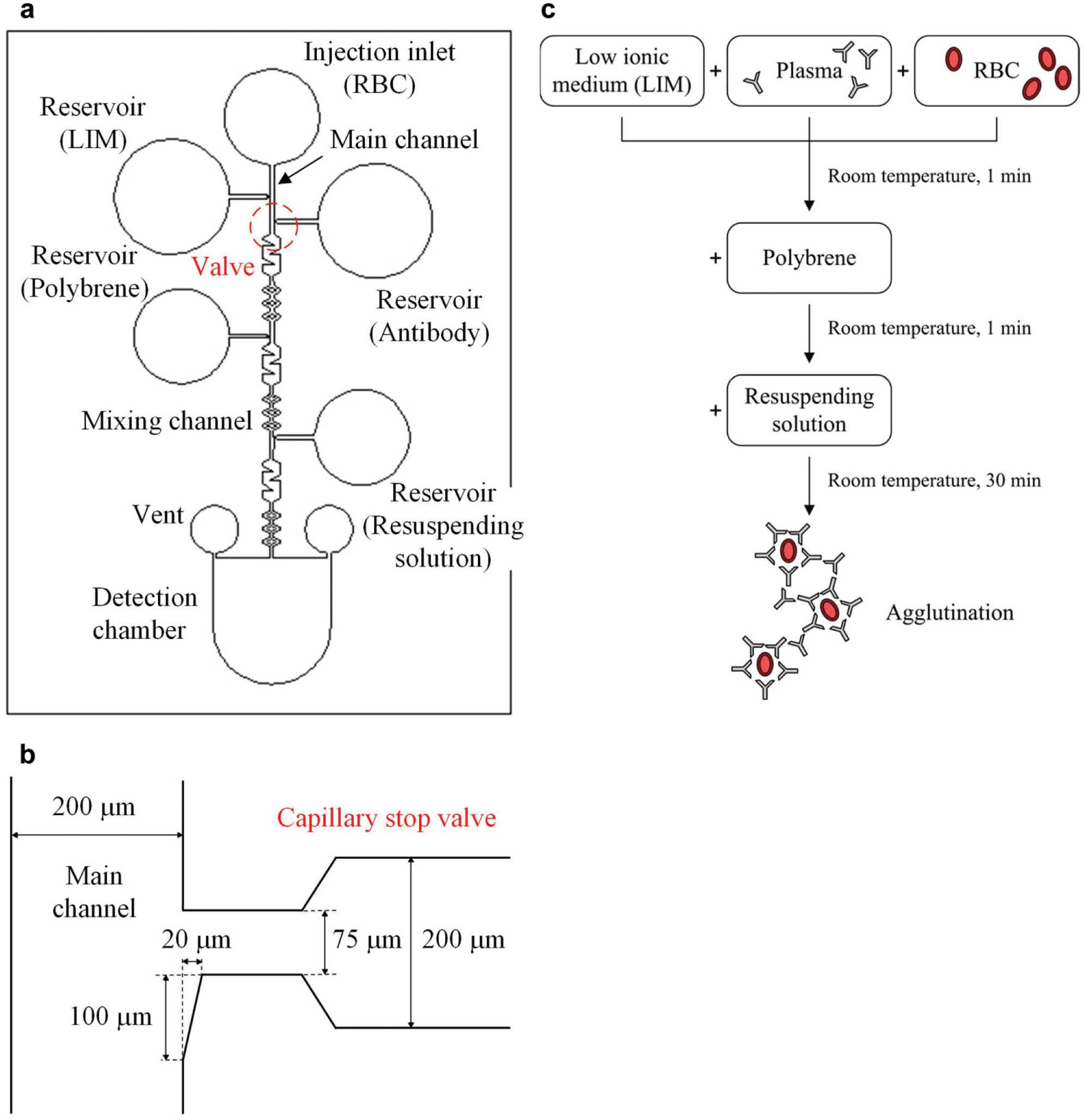
Chip design: (
The dimensions of this proposed capillary stop valve are shown in Figure 1b . It has a chamfered side to hold the injected reagent in the valve position. The chamfered side increases the area of the reagent to come in contact with the specimen; thus, the reagent can be easily dragged out due to the breakdown of its original surface tension.
Chip Fabrication
This proposed chip was produced by bonding the microchannel layer on a glass substrate. To fabricate the microchannel layer, an SU-8 mold with the opposite pattern of all microfluidic components was prepared first, and the microfluidic layer was formed by casting polydimethylsiloxane (PDMS) into the mold. Then, the PDMS microchannel layer was left to cure at 90 °C in an oven for 1 h. Finally, it was carefully peeled from the SU-8 mold.
Prior to the bonding process, the microchannels were filled with 1% bovine serum albumin (BSA) for surface modification. After the microchannel layer was kept stationary for 30 min, the BSA was sucked and wiped out with a cleaning paper. The layer was further dried out by using nitrogen gas. Next, an oxygen plasma treatment for surface modification was conducted on both the PDMS layer and the glass substrate. This process was carried out at a pressure of 1.2 × 10⁻¹ torr for 3 min by decomposing oxygen into OH− to deposit on both surfaces to be bonded. Then, the PDMS layer was placed on the glass substrate and the chip was heated in a 95 °C hot circulator oven for 5 min to complete the bonding process.
Material for Surface Modification
To drive the specimen by capillary force, a hydrophilic microchannel surface is an essential requirement. In this study, BSA was utilized to change the wettability property of the PDMS microchannel from a hydrophobic surface to a hydrophilic surface. A series of concentration gradients of BSA were designed, that is, 1%, 2%, 3%, 4%, and 5%, to investigate the effect on the surface modification.
Biomaterials and Bioassays
Blood typing tests, which require a sequence of added reagents, were adopted to examine the functions of the capillary stop valve. Blood typing is based on the antigen–antibody interaction; if antigens on the surface of RBCs correspond to antibodies in the serum, agglutination of RBCs occurs. For the conventional test protocol, the assay is usually carried out in a 96-well microtiter plate. First, RBCs, the test serum (or plasma), and a low ionic medium (LIM) are added to the microplate. LIM can promote the reaction between RBC antigens and antibodies if they have associated types (e.g., A cell and anti-A). After 1 min of incubation at room temperature, the plate is centrifuged. Then, the supernatant is flicked out of the plate, and one drop of 0.05% polybrene solution is added. The function of polybrene is to cause nonspecific RBC aggregation. After mixing and centrifugation, the supernatant is discarded, and one drop of resuspending solution, which reverses the nonspecific polybrene-induced aggregation, is added. Agitation is thus performed. Finally, agglutination is observed. The procedure is schematically shown in Figure 1c . In this study, the test protocol was modified from the MP technique and is defined as follows. First, 5 μL of antibody, 5 μL of LIM, 2 μL of 0.05% polybrene, and 2 μL of resuspension solution are injected into the respective reservoirs, as shown in Figure 1a , before the introduction of RBCs. All these reagents are kept in the reservoirs by the capillary stop valves. Then, 4 μL of 3% diluted RBCs is injected and traverses the main channel to drag out the reagents one by one for mixing and reaction. Finally, agglutination is observed if it occurs. Antibody screening cells, including A cell, B cell, anti-A, and anti-B, were purchased from Formosa Biomedical Technology Corp. (Taipei, Taiwan).
Results and Discussion
Surface Modification
Without surface modification, PDMS had an average contact angle of 92.15°. After surface modification, the average contact angle was around 45.0° for all BSA concentrations. That is, BSA solutions with different concentration gradients provide similar hydrophilic effects. According to this experimental result, 1% BSA was chosen for surface modification.
Numerical Simulation of Capillary Stop Valve
The numerical simulation of the chamfer-type capillary stop valve was investigated and compared with that of the T-type valve. The so-called T type means that the outer edge neck of the valve has no chamfered side and is shaped like a T. Numerical simulation was conducted by using a finite volume-based commercial computational fluid dynamics (CFD) package, ANSYS FLUENT, which has been adopted for various research endeavors in the microchannel.25–29 To track the interface between the two liquids (A and B), the volume of fluid (VOF) model was used to investigate the flow behavior within a T-type microchannel. Fluid A traverses the main channel, while fluid B is kept by the capillary stop valve. As the simulations focus on the influence of the chamfered design, only the domain near the valve (T junction) was modeled. The stream of A fluid flows with a uniform velocity (0.04 mm/s) in the entrance, and the outflow boundary condition was adopted at the outlet. The quiescent B fluid with zero velocity was initially specified in the right part of the simulated models, and the symmetry condition was utilized at the right boundary. The 2D computational domain was discretized using about 130,000 elements. Simulations with finer grids show a satisfactory grid independence for the results obtained with this mesh.
The transient development of flow behavior near the T-type capillary stop valve is depicted in Figure 2 , where the effect of the chamfered design near the T junction can be clearly observed. The green and red colors indicate the A and B fluids, respectively. Focusing on the T-type model, the B fluid is first pulled out by surface tension as the A fluid passes through the T junction. However, as time elapses, some portions of the B fluid are pulled upstream of the A-fluid flow, as shown in T2 in Figure 2a (T type, 0.25 s). On the other hand, the flow behavior shows a dramatically different pattern as the chamfered design is adopted near the T junction, where the B fluid is pulled out and eventually flows downstream of the A-fluid flow. The countercurrent phenomenon can be clearly detected from the distributions of the streamline, as shown in Figure 2b , where the recirculation eddy can be observed. In other words, the chamfered design is an effective modification in preventing the B fluid from encoutering countercurrent near the T junction.
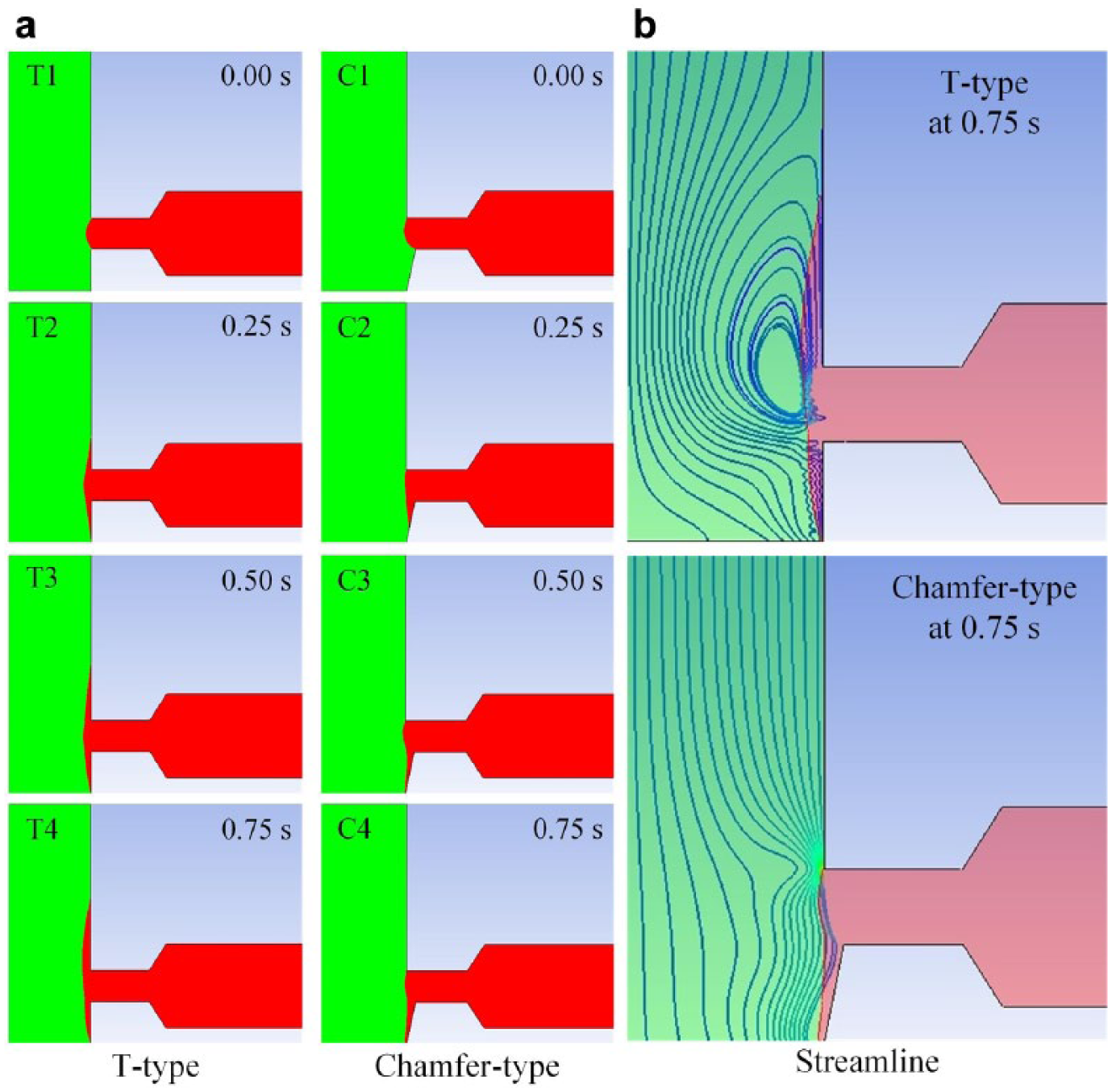
Numerical simulation of capillary stop valve. For the T-type valve, the B fluid (red) is pulled out by surface tension as the A fluid (green) passes through the T junction; however, a countercurrent occurs. For the chamfer-type valve, the B fluid is pulled out and eventually flows downstream of the A-fluid flow without the countercurrent phenomenon.
Experiments of Capillary Stop Valve
In order to confirm the simulation results, experiments using dye solutions were carried out and the performance of the capillary stop valves was studied. The first group of experiments was designed to examine the ability to stop the dye solution at the outer edge neck of the valve. The second group was arranged to investigate the dragging performance. For each test, three chips were used for repetitious experiments.
To test the chamfer-type valve, a red dye solution was injected into a reservoir and the image of its flow behavior was captured using a microscope with backlight source. Moreover, three different indentations, 15, 20, and 25 μm, were investigated. As shown in Figure 3a,b , the flow behavior at a valve with a 15 μm indentation chamfer is similar to that of the T-type valve, meaning the dye solution stopped at the neck outer edge. However, for the valve with a 25 μm indentation chamfer, the situation where the red dye solution directly entered the main channel without stopping at the neck outer edge of the valve, as shown in Figure 3d , had about a 50% chance to occur. The surface tension could not be established due to the larger opening at the neck outer edge. For the valve with a 20 μm indentation chamfer, the solution stopped at the neck outer edge in an asymmetric and protruding form, as shown in Figure 3c . Obviously, the indentation of the chamfered side has significant influence on stopping the reagent.
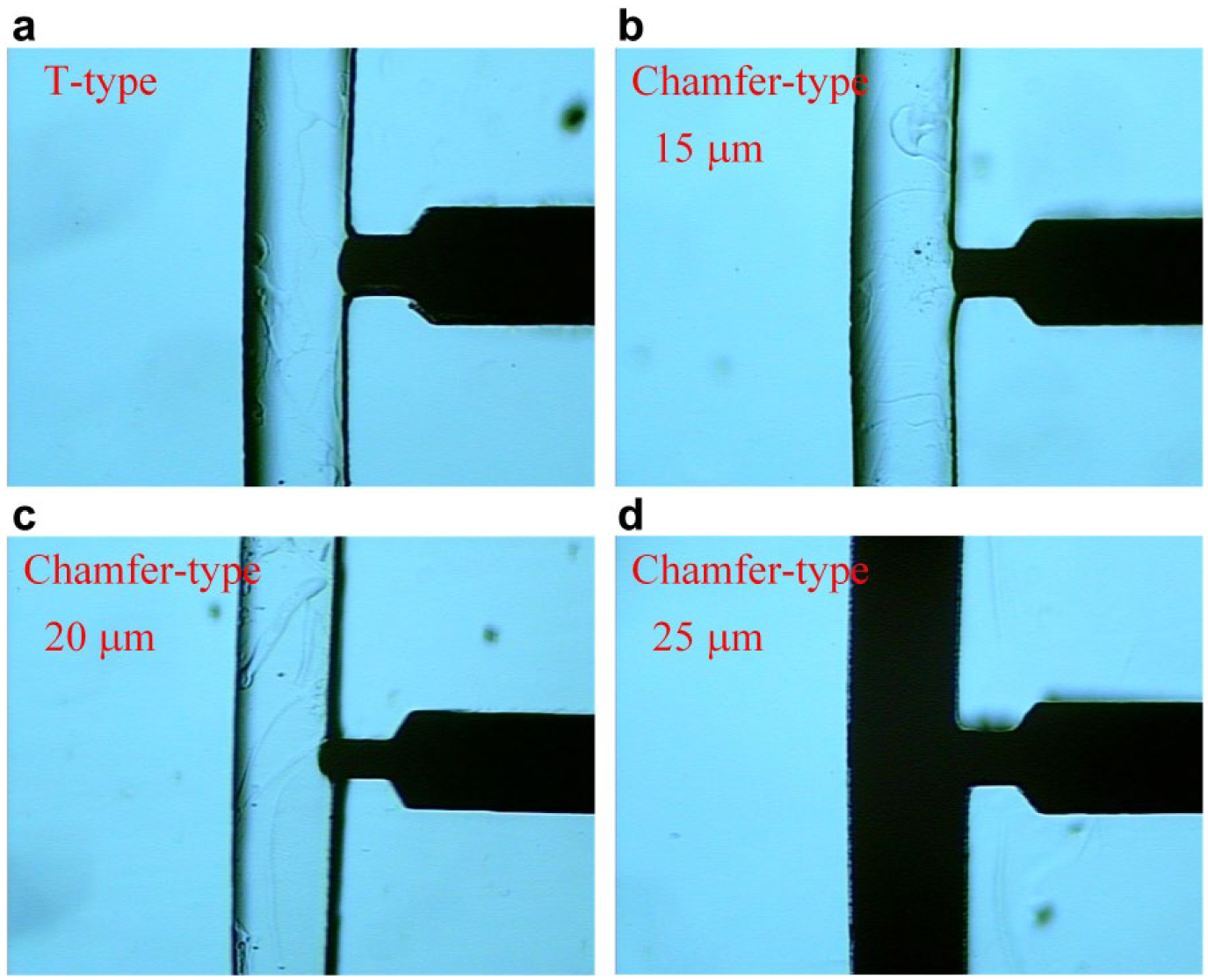
The performance of the stopping fluid at the neck outer edge of the chamfer-type valve with different indentations. The T-type valve and the capillary stop valve with the 15 μm indentation chamfer had similar performance. For the valve with the 20 μm indentation chamfer, the solution stopped at the neck outer edge in an asymmetric and protruding form. The valve with the 25 μm indentation chamfer could not stop the solution at the valve.
Next, the performance of dragging the reagent from the capillary stop valve was tested. Red and yellow dye solutions were used as the test materials, which were injected into the main channel and the reservoir, respectively. Figure 4a−c shows the experimental results. For the T-type capillary stop valve, the countercurrent phenomena, from either the reservoir to the injection inlet or vice versa, were prone to occur. When the red dye solution passed through the capillary stop valve, it broke the surface tension and dragged the yellow dye solution out of the reservoir. However, some of the yellow dye solution flowed toward the injection inlet, and the solution in the inlet became orange. Similar results were also observed for the 15 μm indentation chamfer-type valve. The countercurrent resulted in a serious influence, meaning that the flow might halt without reaching the detection chamber. However, the countercurrent phenomenon was not observed for the 20 μm indentation chamfer-type capillary stop valve. The experimental results agree with the simulation results; thus, an inference can be drawn from this experiment. As shown in Figure 4e , the component of the yellow-dyed flow toward the detection chamber is greater than that toward the injection inlet in a chamfer-type capillary stop valve. As the red-dyed flow in the main channel suffers a smaller interference, the bulk flow traverses toward the detection chamber. On the contrary, the components of flow toward the detection chamber and the injection inlet are identical in a T-type stop valve, resulting in the countercurrent, as shown in Figure 4d . That is also the reason why the red-dyed flow in the main channel halts.
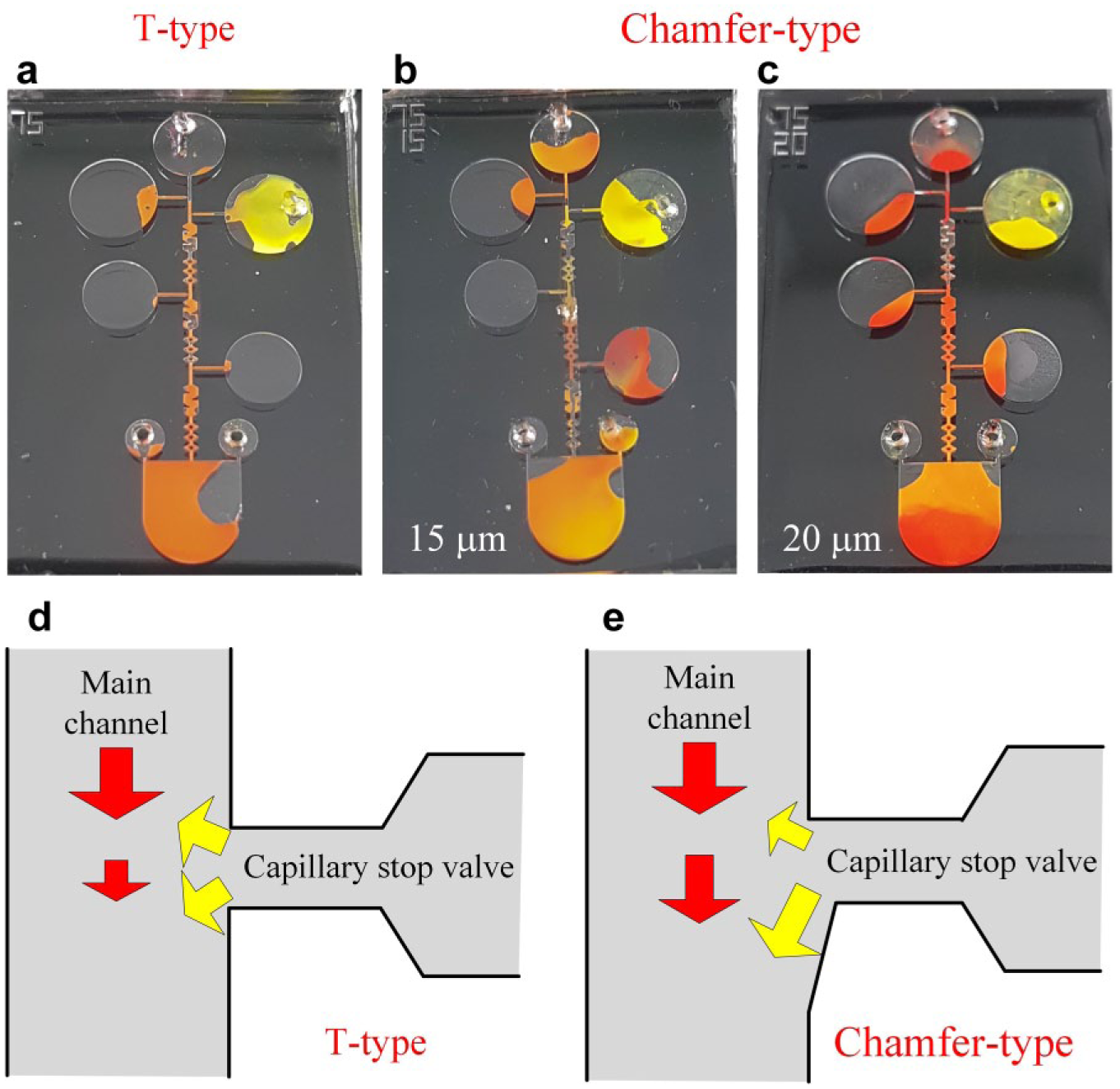
Performance of dragging the reagent from the T-type and chamfer-type capillary stop valves. The yellow dye solution stays at the valve and the red dye solution is introduced into the injection inlet. For T-type and 15 μm indentation chamfer-type valves, the yellow dye solution flowed toward the injection inlet. The countercurrent phenomenon was not observed for the 20 μm indentation chamfer-type capillary stop valve.
Microfluidic Application to Blood Typing Tests
Chips with chamfer-type and T-type valves were implemented in blood typing tests, respectively, for comparison. Assays using A and B antigens were performed. If type A RBCs are exposed to anti-A, agglutination must occur. Similar results must be observed for the experiment of type B RBCs and anti-B. However, for nonagglutination situations, such as type A being exposed to anti-B, most of the reactant solution should not display evident agglutinated blood cells.
The experimental results show that the flow behavior at a chip with a T-type valve was affected by the countercurrent phenomenon, which led to incomplete dragging and a portion of reagents remaining in the reservoir, as shown in Figure 5a . In addition, it cancelled the capillary driving force, and the fluid stopped flowing at the complicated mixing channel. Thus, the blood typing reaction was attenuated. The case of B cell to anti-B, as shown in Figure 5a , is an agglutination case, which looked like nonagglutination. Only small pieces of RBC agglutination can be observed in the detection chamber. On the contrary, the chamfer-type valve reduced the countercurrent phenomenon and ameliorated the blood typing reaction. As shown in Figure 5b , the agglutination cases can be easily discriminated from the nonagglutination cases.
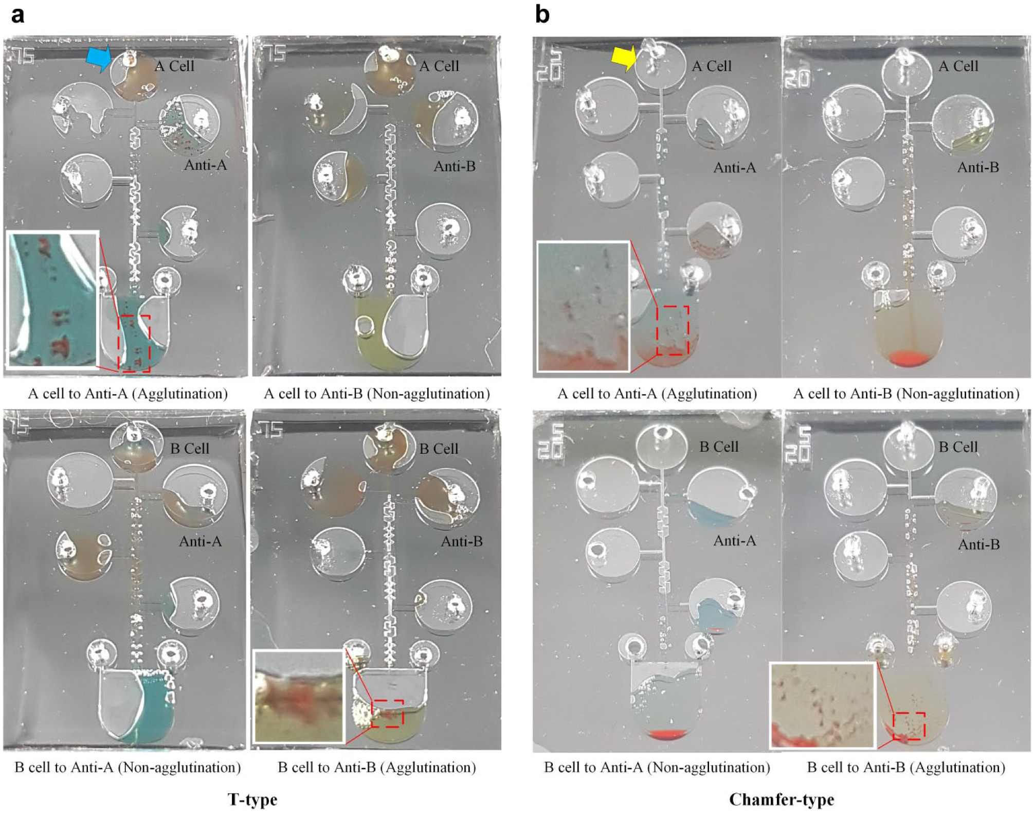
For chips with chamfer-type valves, no specimen remained in the injection chamber (as indicated by the yellow arrow). For the T-type design, a residue of specimen was observed (as indicated by the blue arrow). Thus, RBC agglutination is unapparent in a chip with T-type valves. The agglutination cases are discriminated from the nonagglutination cases in chips with chamfer-type valves.
The capillary force-driven microfluidic network is an elegant solution to achieve a portable diagnostic system for point of care, and no flow manipulation apparatus is required. The capillary stop valve is then a requisite component for the microfluidic network due to its simple geometrical structure. Nevertheless, accurate manipulation of the microfluids is significant. From our simulations and experimental results, the countercurrent phenomena were observed in the commonly used T-type capillary stop valve. Therefore, the blood typing reaction was attenuated, as the countercurrent led to incomplete dragging and the fluid stopped flowing at the complicated mixing channel. This result is not allowed, as blood typing is a critical test to ensure the serological compatibility of a donor and a recipient. On the contrary, the chamfer-type valve reduced the countercurrent phenomena and ameliorated the blood typing reaction. Agglutination results can be easily discriminated from the nonagglutination cases. This proposed chamfer-type capillary stop valve improves the performance of flow regulation, and its application to the blood typing chip allows us to use minute amounts of blood samples and reagents; thus, the chip provides great potential for blood typing in emergency situations.
Footnotes
Declaration of Conflicting Interests
The authors declared no potential conflicts of interest with respect to the research, authorship, and/or publication of this article.
Funding
The authors disclosed receipt of the following financial support for the research, authorship, and/or publication of this article: This work was supported by the Ministry of Science and Technology (MOST) of Taiwan (grant number MOST 106-2221-E-033-069).