
Abstract
This study aimed toward the wearability of the antenna by inspecting the probability of designing and fabricating a wearable microstrip antenna operating from 2 to 6 GHz, centered at 2.5 GHz and 5.3 GHz. The antenna is fabricated from jeans material with dielectric constant εr = 1.7 and a thickness of 1 mm. The proposed design is simulated on High-Frequency Simulation Software (HFSS) version 2015, followed by fabrication using a 50-µm copper film on a jeans substrate. Anritsu MS2038C VNA Master then tests the fabricated design. Also, specific absorption rate (SAR) values are computed for medical applications to account for tumor detection in human breast tissue.
Introduction
Wearable antennas are getting more attention nowadays because of their comfort and their ease of integration into daily wear. Related to biological applications, these wearable sensor antennas are capable of interconnecting with nearby devices wirelessly, referred to as body-centric networks.1–3 However, the performance of these wearable antennas suffers from certain losses in terms of gain, efficiency, and impedance matching when they are subjected to the human body depending on antenna design complexity or the characteristics of the wearable materials. These challenges provide hindrances in the reliability and development of wearable devices for body-centric communications.4,5 The human body’s effect on the various parameters of the antenna has been analyzed through homogeneous6–9 and heterogeneous human models.10,11
Despite such obstacles, wearable antennas have become an area of research, and in this regard, many research articles have been published as reported in the works of Langenhove, 12 Park and Jayaraman, 13 and Sankaralingam and Gupta. 14 Wearable antennas use different textiles such as jeans, cotton, nylon, fleece, polyester, and so on,15–18 which are comfortable to wear and can be incorporated into clothing for various measurements. Wearable antennas have numerous applications in different fields, namely medical, sports, defense, and so on.19–24
So far, different textile substrates have been used in designing wearable antennas. The work presented in this article contributes to the design and fabrication of wearable antennae using jeans as the substrate for medical and WiMAX applications. The permittivity of jeans (textile substrate) is used for the simulations. The copper foil acts as the conducting medium for the radiating element (patch) and the ground plate. Copper foil is resistant to high temperatures, malleable, and water resistant, hence a suitable choice for the radiating element. All the simulations are done on High-Frequency Simulation Software (HFSS) as well as on Computer Simulation Technology (CST). The measurements are performed on Anritsu MS2038C VNA Master.
The proposed antenna works from 2 to 6 GHz with resonant frequencies at 2.5 and 5.3 GHz. The 2–6GHz band is an interesting band to implement as it does not require line-of-sight communication and can be useful for end-to-end communication wirelessly, and making wearable devices to work in this band can be an additional feather in the cap. The permittivity of the substrate (jeans) used is 1.7 with 1-mm thickness. First, a rectangular patch with a hexagonal slot at the center is simulated, which does not provide the required bandwidth. Therefore, slots are added at the edges of the rectangular patch and at the center of the hexagonal slot, which provides more current flow through the edges, thus increasing the bandwidth of the antenna. The addition of slots adds resonant frequency, making it suitable for both medical and WiMAX applications. This work also illustrates the manufacturing process of the inexpensive conductive tape-based wearable antenna instead of the conducting thread used in the embroidery-based fabrication method.25,26 The designed antenna is then fabricated through the steps mentioned in the upcoming section followed by the measurement on VNA. The proposed antenna can be embedded into garments to detect the presence of a tumor through variations in the reflection coefficient values and monitor the heart rate and temperature of the human body. The article is organized as follows: The following section presents the wearable antenna design. The “Fabrication of the Wearable Antenna” section represents the fabrication process with the measurement results, followed by the “Specific absorption rate computation” and “Conclusion.”
Design of a Wearable Antenna Using Jeans as the Substrate
The modeled wearable antenna is printed on 1-mm-thick jean fabric with L × W = 50 mm × 35 mm, respectively, as shown in Figure 1(a) and (b), designed to operate around 2.45 GHz and 5.3 GHz, considered as a suitable frequency for health care and wireless applications. The area of the conductive patch is 611.37 mm2. In the full-wave simulations, the patch was fed by microstrip feed using an ideal lumped port.
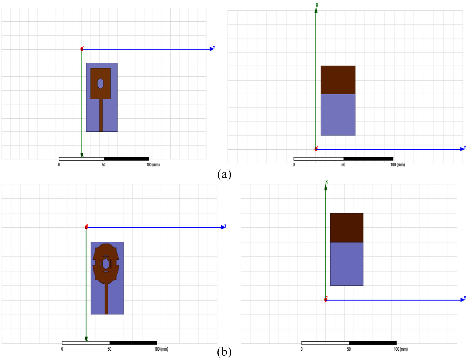
(a) Top (left) and bottom (right) of antenna A. (b) Top (left) and bottom (right) of antenna B.
The design starts with a rectangular patch having a hexagonal patch at the center of the rectangular patch and a partial ground plane with dimensions 20 × 35 mm (Lp × Wp) as shown in Figure 1(a), referred to as antenna A. The antenna A gives the perfect matching at 2.4 GHz with the S11 at −25.8 dB and −12 dB at 5.3 GHz. To provide the entire band from 2 to 6 GHz for wireless communication, the circular ring and rectangular slot have been subtracted from outside the patch and inside the hexagonal slot as shown in Figure 1(b), referred to as antenna B. Both the antennas are designed and simulated in HFSS v.15.0 based on the finite element method (FEM).
The dimensions of modeled antenna (antenna B) are shown in Figure 2(a) with the simulation result as shown in Figure 2(b), providing the band from 2.28 to 3 GHz, centered at 2.5 GHz and 4.5–6 GHz, cornered at 5.3 GHz.
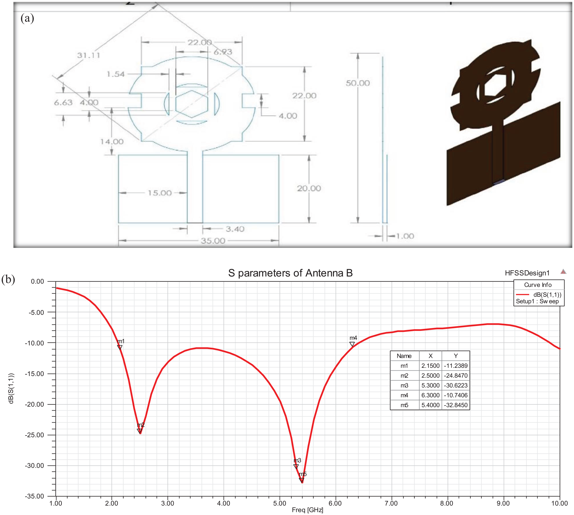
(a) Physical dimensions of antenna B. (b) Reflection coefficient values of antenna B.
The comparison of simulated results for antenna A and antenna B is illustrated in Figure 3, depicting the 2–6 GHz band for antenna B. Antenna A gives one resonant peak at 2.4 GHz and a very small bandwidth. With the addition of slots in antenna A, current flows through edges, thus providing two resonant peaks (2.5 GHz and 5.3 GHz) and 2–6 GHz bandwidth in antenna B. To further verify the design, the antenna B has been simulated in CST. The reflection coefficient plot for the same can be observed in Figure 4, which is similar to the result obtained through the FEM in HFSS. Thus, the simulation results in Figures 3 and 4 are compatible and verified.
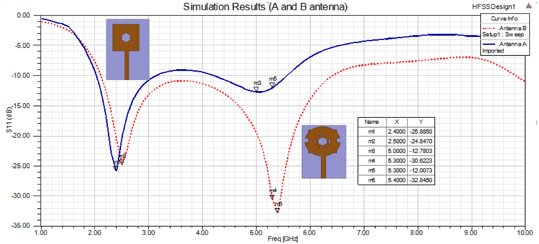
Simulation results for antenna A and antenna B.
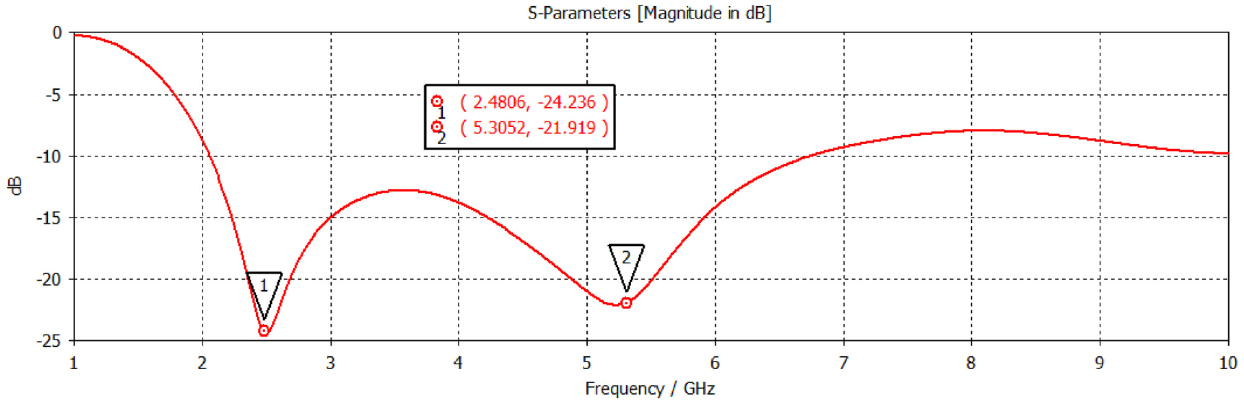
Simulated reflection coefficient results of wearable antenna on jeans in CST.
Surface Current Distribution
The surface current distribution of the modeled antenna (antenna B) for two resonant frequencies (2.5 and 5.3 GHz) is shown in Figure 5(a) and (b). The surface current distribution at 2.5 GHz is shown in Figure 5(a), which is found to be 26.3 A/m2. The major current distribution is around the lower corner of the patch, and uniform current distribution is observed throughout the whole patch of the antenna. Therefore, adjusting the lower corners of the patch may adjust the lower frequency band. In Figure 5(b), the surface current distribution of 59.6 A/m2 at 5.3 GHz is displayed. A large amount of surface current gets distributed at the upper part of the patch and inside the inner circle of the radiating patch. This indicates the upper horizontal slot is responsible for the upper-frequency range.
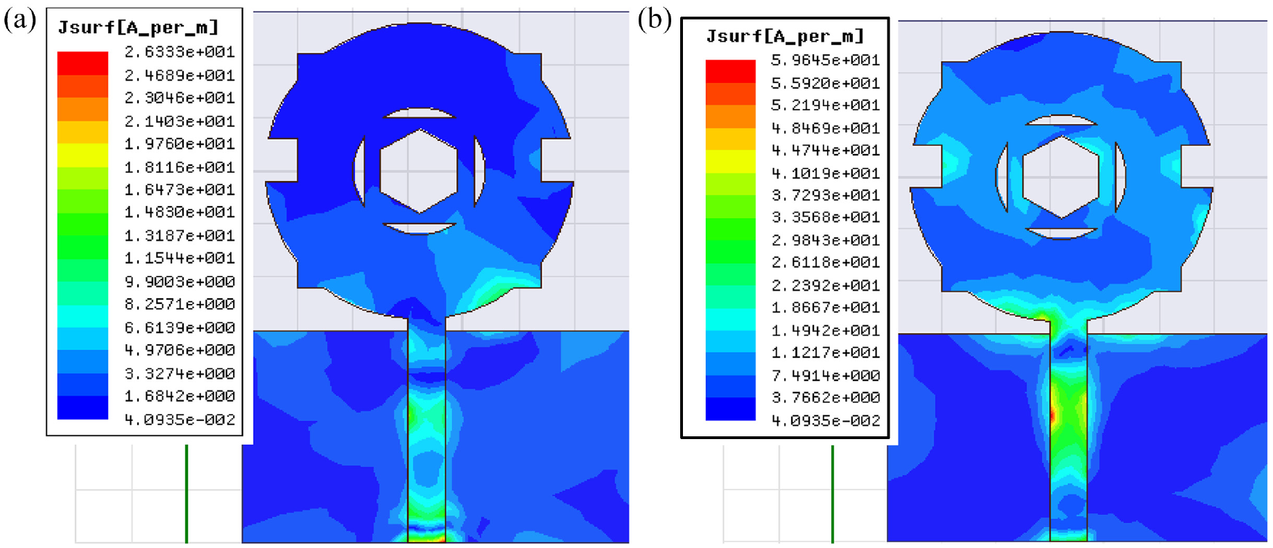
Surface current distribution at (a) 2.5 GHz and (b) 5.3 GHz.
Radiation Pattern and Gain
The spreading of radiated power density by the antenna is represented through the radiation pattern of the antenna. It is the depiction of electromagnetic wave radiation in the far field zone. 27 The simulated radiation pattern for E- and H-planes at 2.5 and 5.3 GHz is shown in Figures 6 and 7. More energy is radiated in the E-plane at 2.5 GHz, whereas the reverse is observed at 5.3 GHz, where there is more radiation of energy in the H-plane than in the E-plane. Also, at 5.3 GHz, the back lobe in E-plane is more evident.
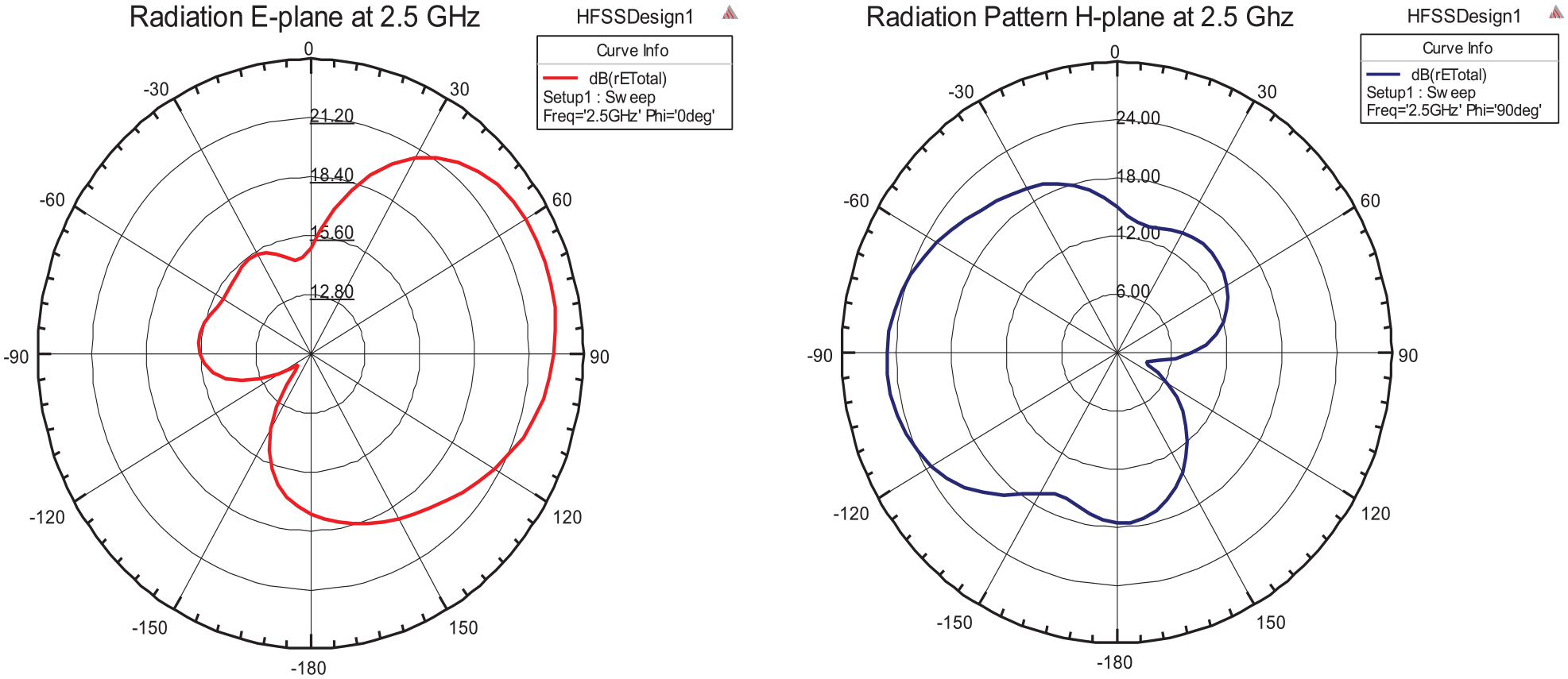
Radiation pattern at 2.5 GHz in E-plane (left) and H-plane (right).
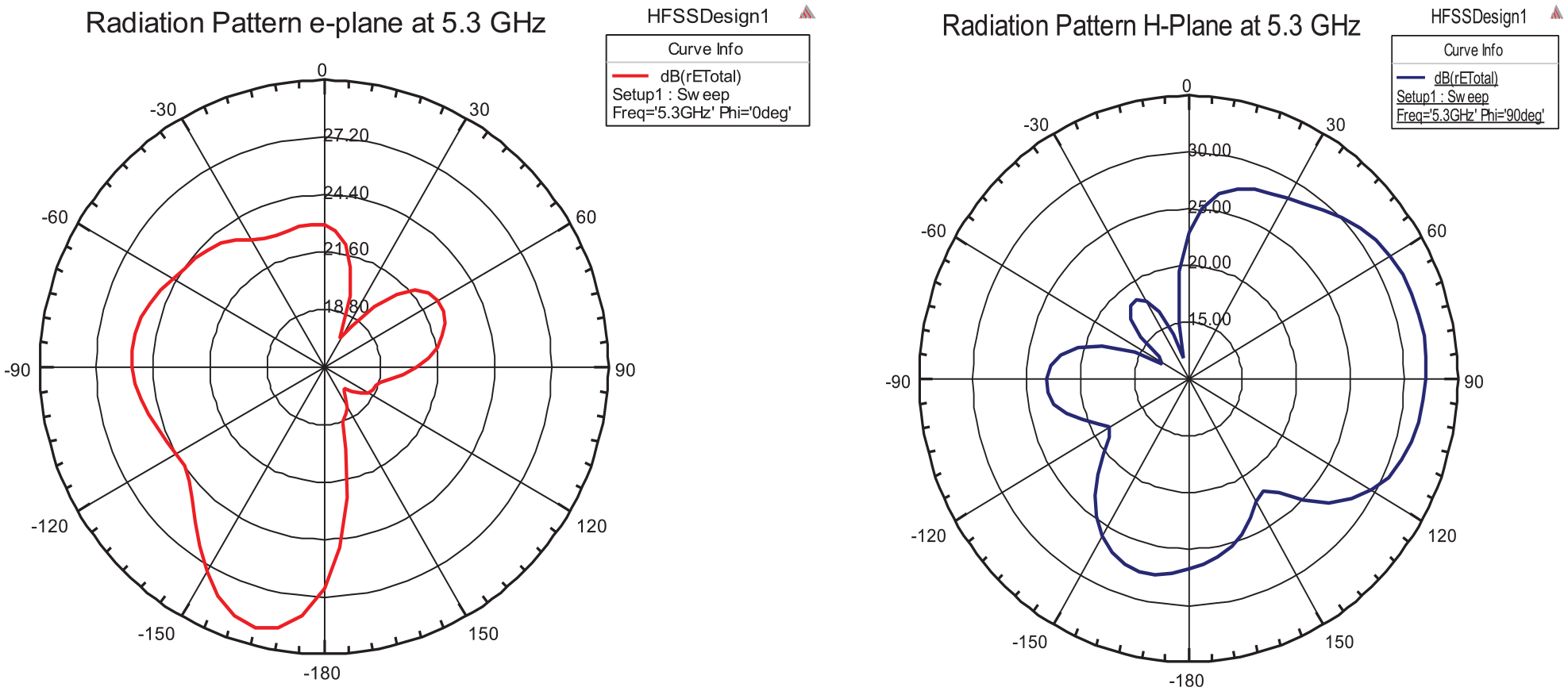
Radiation pattern at 5.3 GHz in the E-plane (left) and H-plane (right).
The gain of the antenna illustrates power transmission in the direction of maximum radiation at 2.5 GHz and 5.3 GHz as observed in Figure 8(a) and (b), respectively.
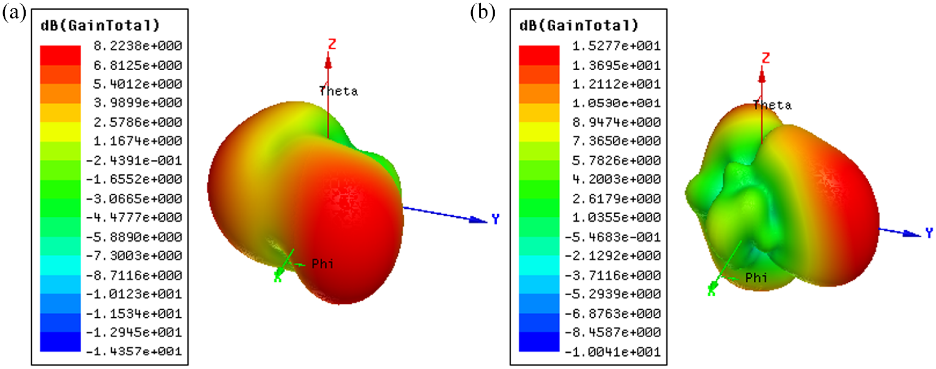
Gain (a) 2.5GHz and (b) 5.3 GHz.
The gain at 2.5 GHz is obtained as 8.2 dB and 15.2 dB at 5.3 GHz. To further validate the results, co-polarization and cross-polarization in both the E- and H-planes are observed at 2.5 and 5.3 GHz. As seen from the 2-D polar plot (Figure 9), the radiated energy is somewhat elliptically polarized. The level of cross-polarization in the H-plane is slightly higher at 5.3 GHz because of the high gain value at 5.3 GHz. The high gain values expand the plot while lower gain values make all the patterns shrink toward the center.
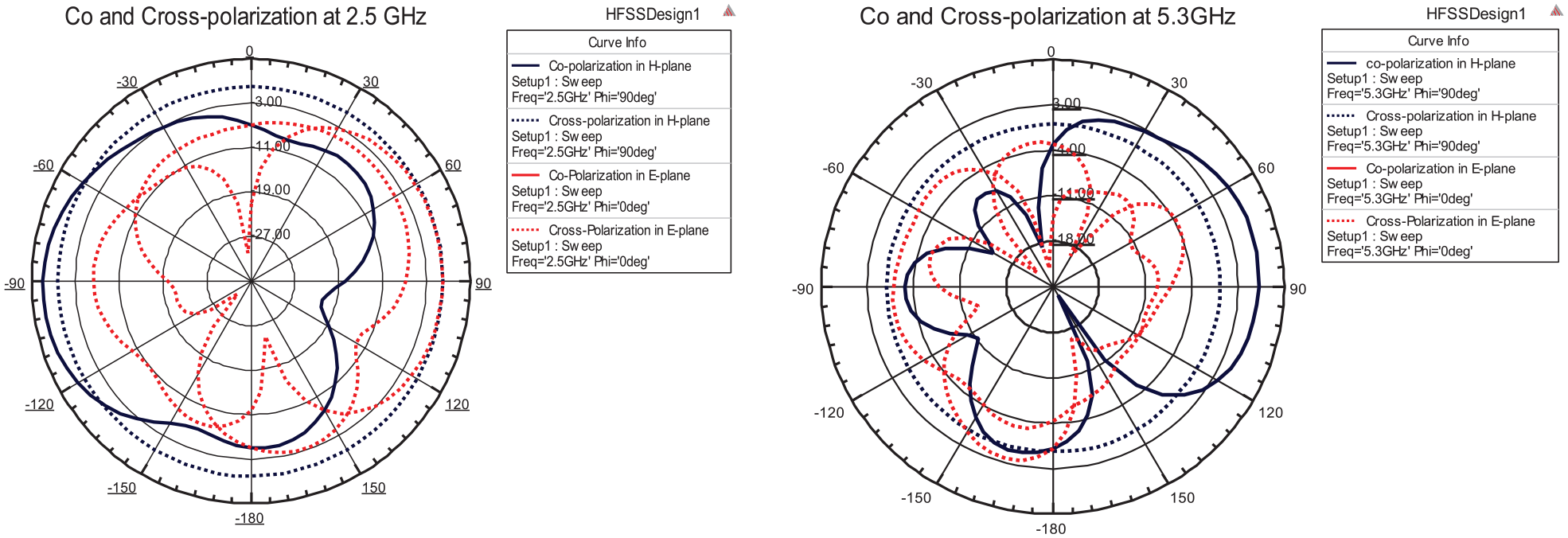
Co- and cross-polarization at 2.5 GHz (left) and 5.3 GHz (right).
Fabrication of the Wearable Antenna
There are various methods to design the conductive parts of the fabric-based antennas, using conductive inks27–29 and conductive threads with an embroidery machine. 30 We have adopted a low-cost copper sheet for designing the conducting part of the antenna. The design involves manually attach in the antenna to the jeans fabric through high heat and pressure through the hydraulic press which is further etched using formaldehyde solution.
The fabrication of the antenna on jeans is explained with the help of a flowchart, following the steps in detail, as given in Figure 10.
Conversion of an HFSS File into a DXF file. After conversion, the DXF file is hatched using AutoCAD 2021 software for printing the design on a high-quality sheet of Kodak paper.
The printed design is then placed on the copper sheet using ethanol solution pressed under high heat and pressure.
After applying high heat and pressure through a hydraulic press onto the copper-containing design, the design is immersed in water to remove the excess paper around the design as shown in Figure 11.
After removing the excess paper, the desired patch and ground structure on the design are covered through adhesive tapes and immersed into the formaldehyde solution for the etching process.
After 20 min, the etching process is completed, and the patch along with the ground part is glued to the fabric through a hot glue gun and again pressed onto the fabric.
When the patch and the ground part get pasted properly on the fabric, the 50 Ω connector is soldered to the patch’s feeding point for testing.
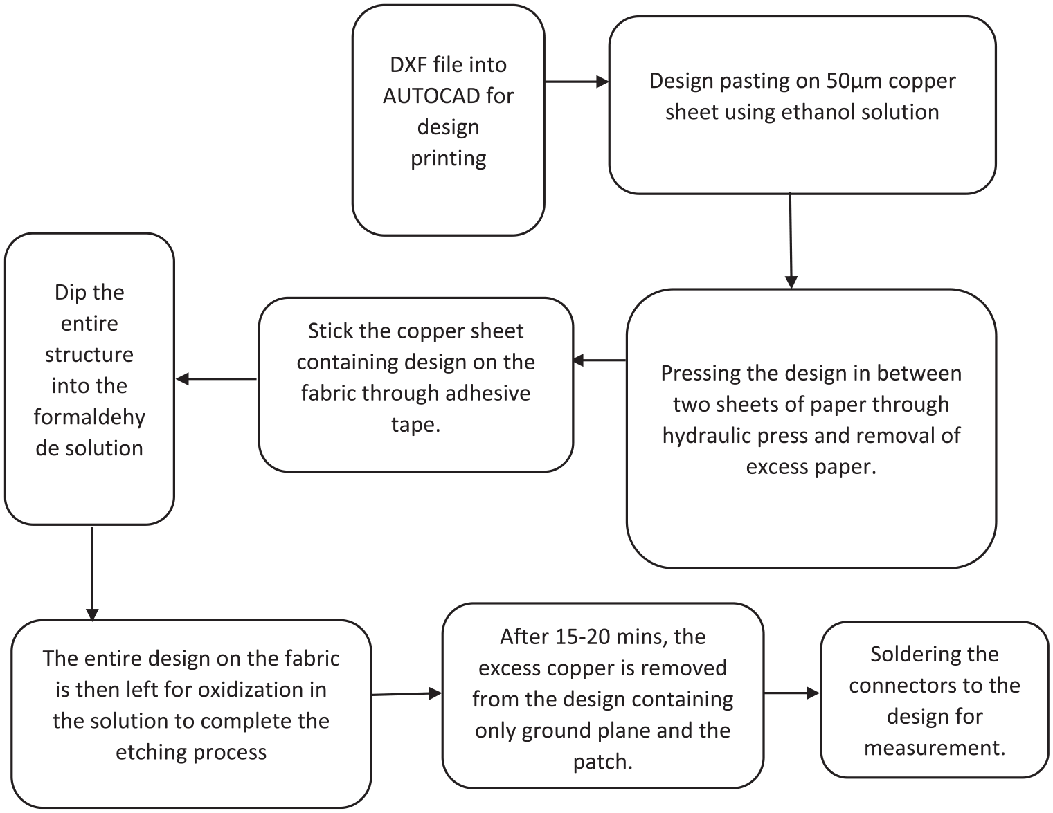
Flowchart of the entire fabrication process of the wearable antenna.
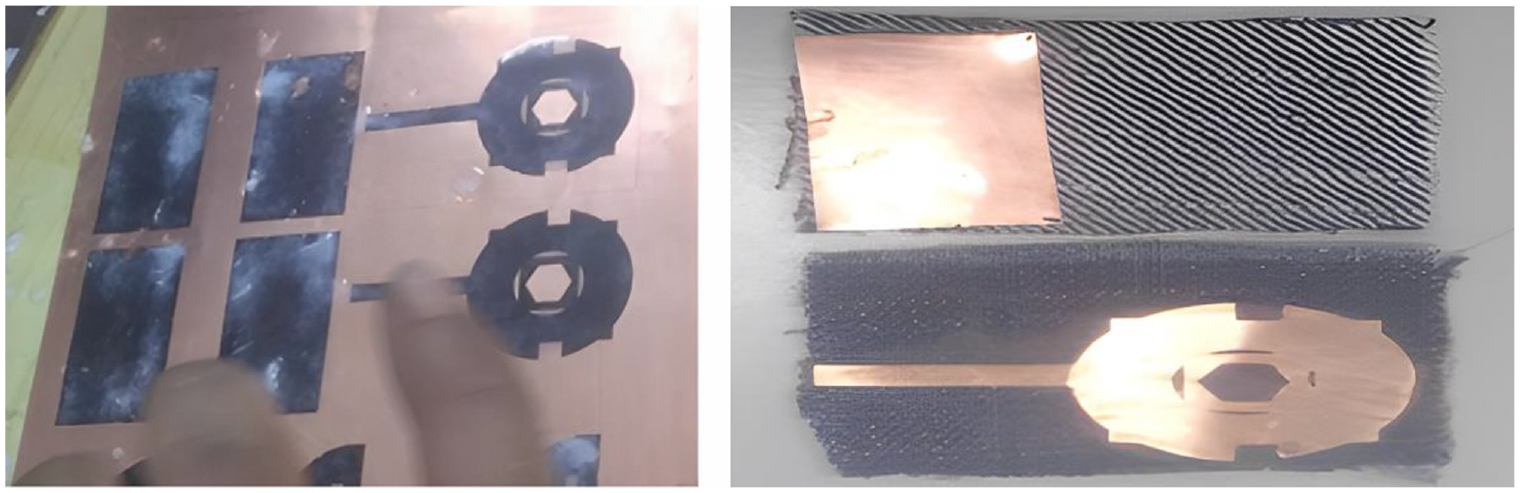
Removal of excess paper from the design using a water solution and the fabricated antenna on jeans after the etching process.
The fabricated wearable antenna is measured through Anritsu MS2038C VNA Master as shown in Figure 12.
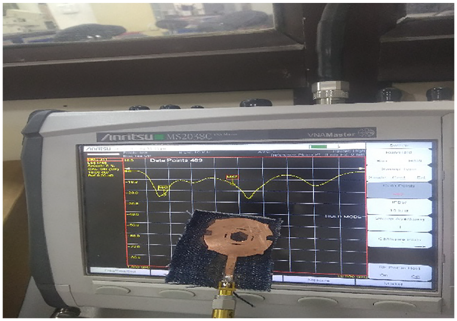
The measurement setup.
The VNA was first calibrated using an open, short, and load calibration process, and after that, the designed antenna is connected to VNA through a 50-Ω connector. The comparison of simulated and measurement results is shown in Figure 13. There is a slight variation in the reflection coefficient values (2.5 GHz to approximately 2.4 GHz, an advantage from a health care application point of view) during the measurement process which might be due to the rough edges of the fabric or the burning of the jeans material during the soldering process. Also, the copper sheet might have breaks or dirt which can be responsible for the deviation of measurement results from the simulated results.
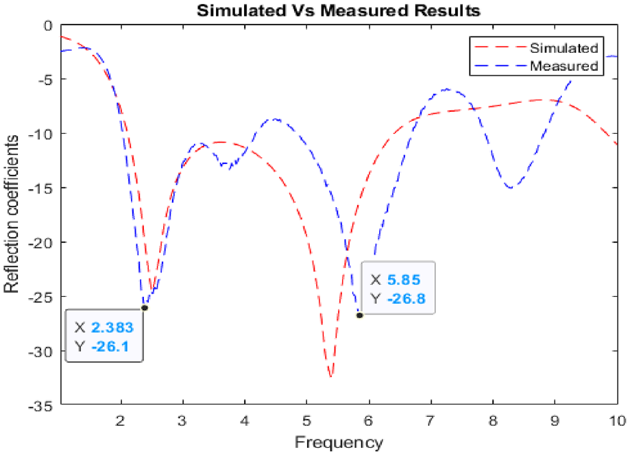
Simulation versus measurement results of wearable antenna (jeans).
Specific Absorption Rate Computation
The placement of the antenna closer to the human surface suffers from mismatching, and part of the signal gets reflected/absorbed by the human tissues, which leads to a high specific absorption rate (SAR). 31 SAR accounts for the measurement of wave absorption or penetration inside human tissues. Mathematically, SAR is defined in terms of the electric field as in equation (1).
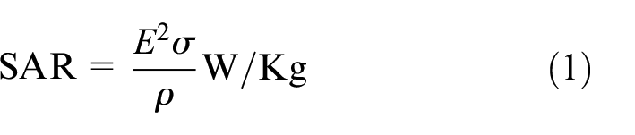
where E is the electric field,
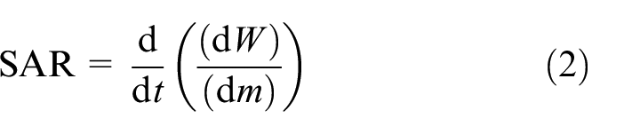
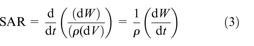
Also, it can be expressed as the energy dissipated (dW) per unit mass (dm) in a volume (dV) of a given density (
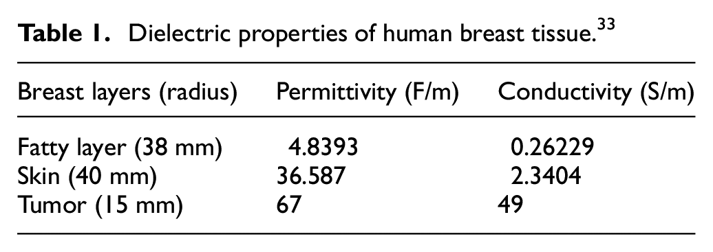
The SAR value at 2.5 GHz for 1 W of power in human breast skin is observed as 0.04 W/kg when the wearable antenna is placed at a distance of 8 mm from the breast tissue as shown in Figure 15. The healthy standards for the SAR limit set by the United States are 1.6 W/kg per 1 g of tissue, and it is 2 W/kg per 10 g of tissue according to the European Union. 32 The designed wearable antenna is meeting the standard limits of SAR for the detection of tumors in the human breast tissue at 2.5 GHz. The dielectric properties of breast tissue considered for SAR measurement are tabulated in Table 1.
Dielectric properties of human breast tissue. 33
For tumor detection, a spherical structure with a radius of 15 mm is considered, which increases the SAR to 0.015 W/kg at 2.5 GHz, which is greater than that of healthy breast tissue as shown in Figures 14 and 15. A higher specific absorption rate indicates the presence of a tumor at 2.5 GHz.
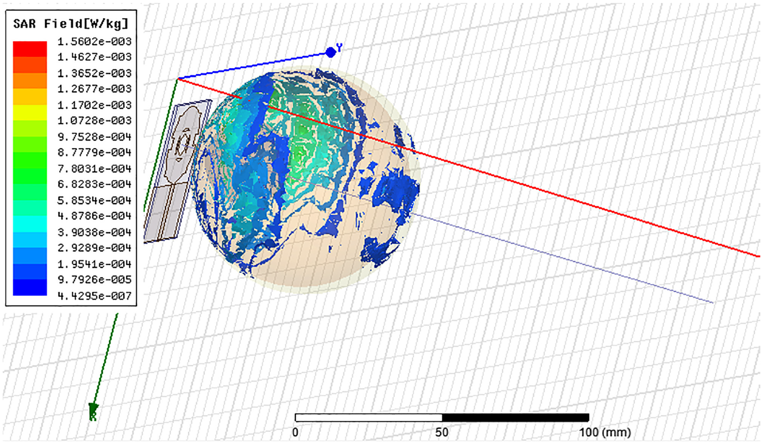
SAR value at 2.5 GHz for a 1 W power source containing a tumor.
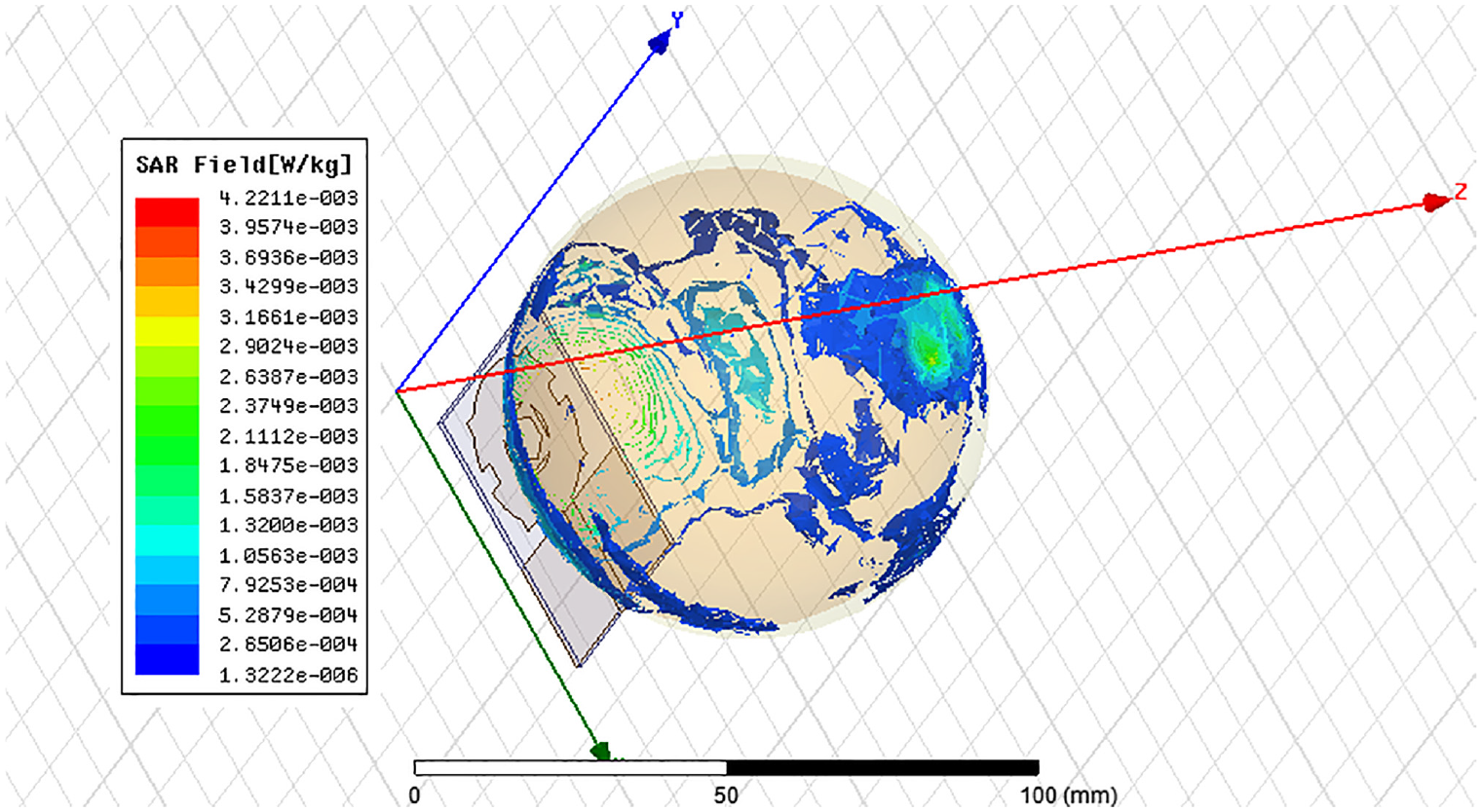
SAR value at 2.5 GHz for a 1 W power source in healthy breast tissue.
Increased value of SAR in unhealthy tissue (tumor) in comparison to healthy tissue (no tumor) showing the detection of the tumor with the designed antenna as given in Table 2. The comparison of the proposed work with previous works has been tabulated in Table 3.
Comparison of SAR values.
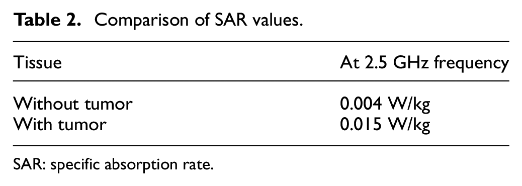
SAR: specific absorption rate.
Comparison with previous works.
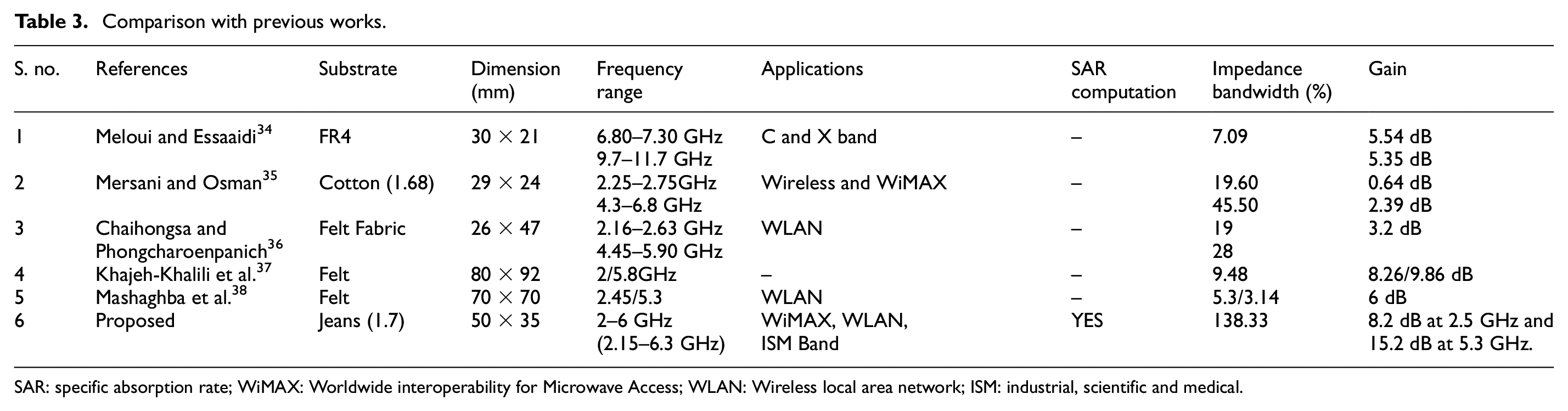
SAR: specific absorption rate; WiMAX: Worldwide interoperability for Microwave Access; WLAN: Wireless local area network; ISM: industrial, scientific and medical.
Conclusion
The following article represents the design and fabrication of a low-cost wearable microstrip patch antenna on jeans material operable at 2.5 GHz and 5.3 GHz with a band of 2–6 GHz to achieve the wearable antenna in reality. The jean material has a dielectric property of 1.7 with a thickness of 1 mm simulated using HFSS. The surface current density, gain, and radiation pattern are observed at 2.5 GHz and 5.3 GHz. Furthermore, the SAR value is also computed for the human breast tissue for cancer-detection purposes for a 1 W power source. Higher values of SAR in breast tissues containing tumor in comparison to healthy breast tissues (without tumor) indicate the presence of a tumor. The wearable antenna was fabricated manually using a low-cost copper sheet and tested using Anritsu MS2038C VNA master. The measured results are somewhat matched closely to the simulated results. The future works of this study involve the experimental analysis of this wearable antenna on tumor-containing breast tissues (homogeneous and heterogeneous).
Footnotes
Declaration of conflicting interests
The author(s) declared no potential conflicts of interest with respect to the research, authorship, and/or publication of this article.
Funding
The author(s) received no financial support for the research, authorship, and/or publication of this article.