
Abstract
The success of dental implant depends on meticulous treatment planning. Restorative problems are often common with improper placement of implants, especially where the alveolar bone quantity is compromised. The accuracy needed in placement of the mini-implant is even more. Hence, the use of a surgical guide becomes essential. Various authors have suggested techniques for the fabrication of surgical and radiographic stents. These techniques make use of different materials in fabrication of stent. This article presents a simple technique for the fabrication of a surgical guide for the placement of mini-implants using simple readily available materials. The technique can be modified to be used for regular diameter implants.
Keywords
Introduction
The success of dental implants depends on proper treatment planning. Proper implant angulation during the surgical procedure is another determinant of implant success. In com-promised cases, implant placement, which is based on available bone, often results in poor esthetic outcomes as well as long-term biomechanical instability. Surgical guides can help control the implant placement angle if they are made and used correctly. 1 Choi et al investigated the effects of dimensional factors (diameter, length, and distance between the underside of the surgical guide and the implant recipient site) of the surgical guides on implant placement and found that the length of the guide channel was the primary factor in reducing angle deviations in the mesiodistal and buccolingual directions. 2 Various authors3-8 have suggested different techniques for the fabrication of surgical and radiographic guide using different materials—vacuum-formed sheets, drill inserts, metal sleeves, brass tubes, lead strips, gutta-percha guides, set-up disks, and light poly-merized composite resin, computer-aided design (CAD)/computer-aided manufacturing (CAM). The template should be stable and rigid when it is in the correct position. 9
This article describes a technique for the fabrication of the surgical guide using readily available materials. The technique is simple, used for the placement of mini-implants, but can be modified for the placement of regular diameter implants.
Technique
A 34-year-old patient visited the Department of Prosthodontics for replacement of his missing mandibular anterior teeth 41 and 42 with Ellis Class IV fracture wrt 31. Implant-supported prosthesis was planned for missing teeth 41 and 42. Fractured tooth 31 was decided to be restored using post and core after the endodontic treatment of the same. The patient was explained about the procedure, and the required consent was obtained. Implants were placed using surgical guide for accurate placement of the implants at the desired site. The following technique was used for the fabrication of the surgical guide.
Diagnostic Wax-up Done
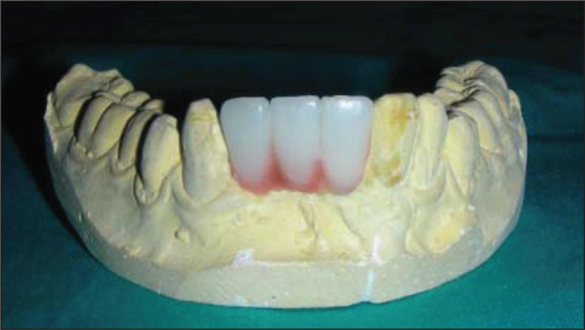
Wax-up of the missing teeth to be replaced was prepared with a thin layer of wax extended to the adjacent surface of the teeth lingually for extra stability of the stent (Figure 1).
The model along with the wax-up in position was duplicated using an irreversible hydrocolloid (Zelgan 2002, Dentsply) and poured in dental stone Type III (Kalstone, Kalabhai).
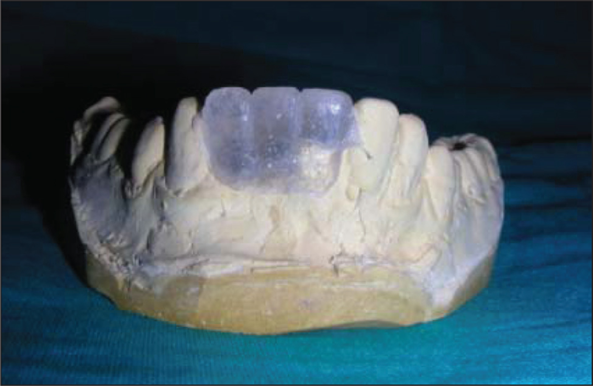
A thin (1-mm-thick) vacuum-formed sheet was adapted over the duplicated working model. The vacuum-formed template was then transferred back to original master cast (Figure 2).
Vacuum-Formed Sheet Adapted Over Master Cast
A minimum of 2 reference points are needed to determine the ideal angulation and path of insertion of the implants in the surgical stent to be fabricated.
First reference point
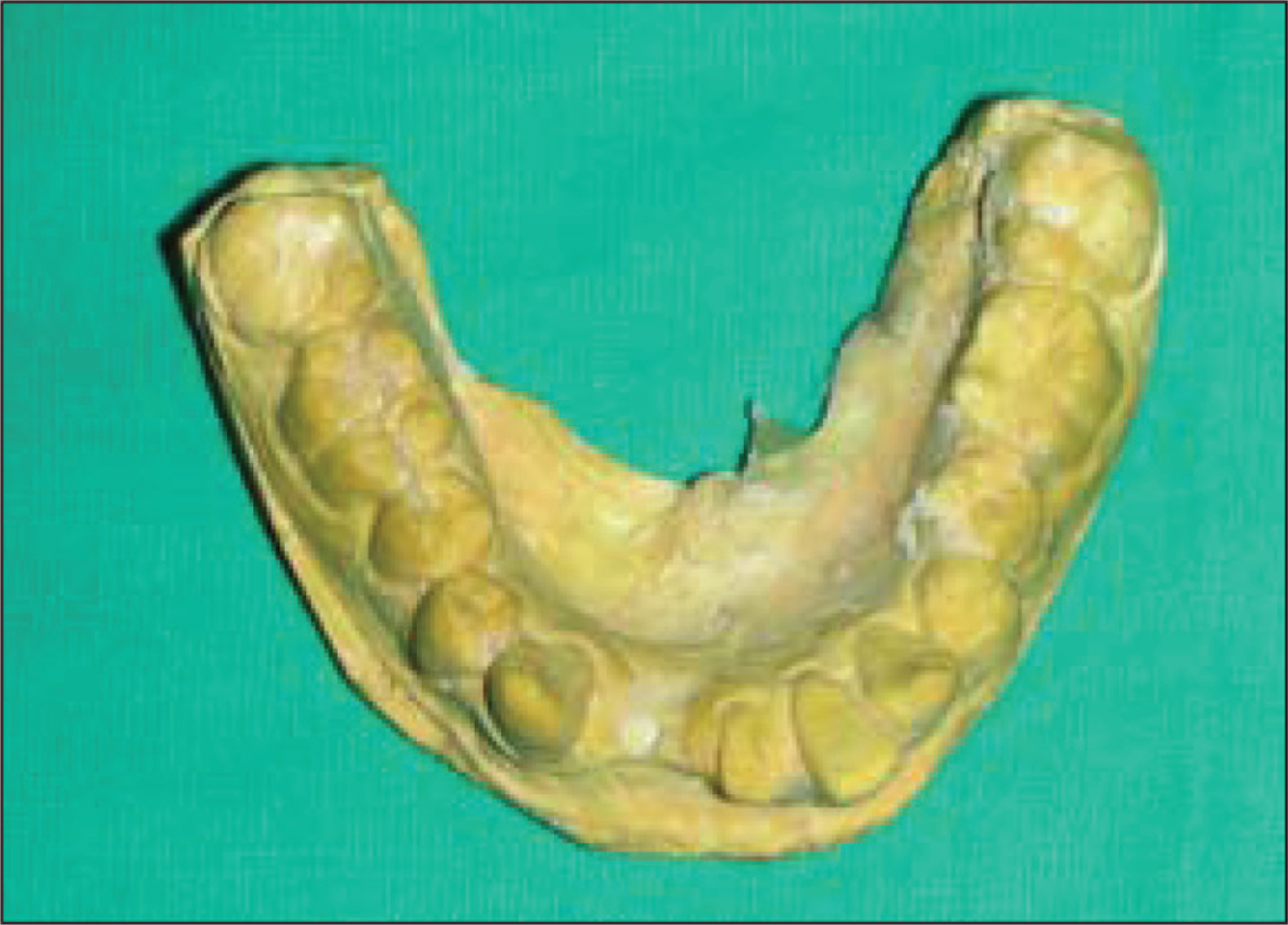
A dot was marked at the proposed site of implant on the master cast, based on the radiographic assessments. The position was so located that labiolingually more than 0.5 mm of the bone was present on each side of the implant. Mesiodistally the implant position was at least 1 mm from the adjacent tooth. A small hole was drilled on the master cast at the first reference point so that the metallic bur may remain stable (Figure 3).
Hole Drilled on Master Cast at the First Reference Point
Second reference point was chosen as the incisal edge of the teeth to be replaced as cement-retained prosthesis was planned (Figure 4).
Proposed Implant Position Marked With Indelible Pencil
A hot probe was used to make a small hole on the vacuum-formed template at the site of the second reference point.
The nonworking end of a small metallic bur (2 mm in diameter, measured using a metal gauge) routinely used was inserted in the hole made on the template, connecting the 2 reference points (Figure 5).
Nonworking End of Bur Inserted Connecting Reference Points
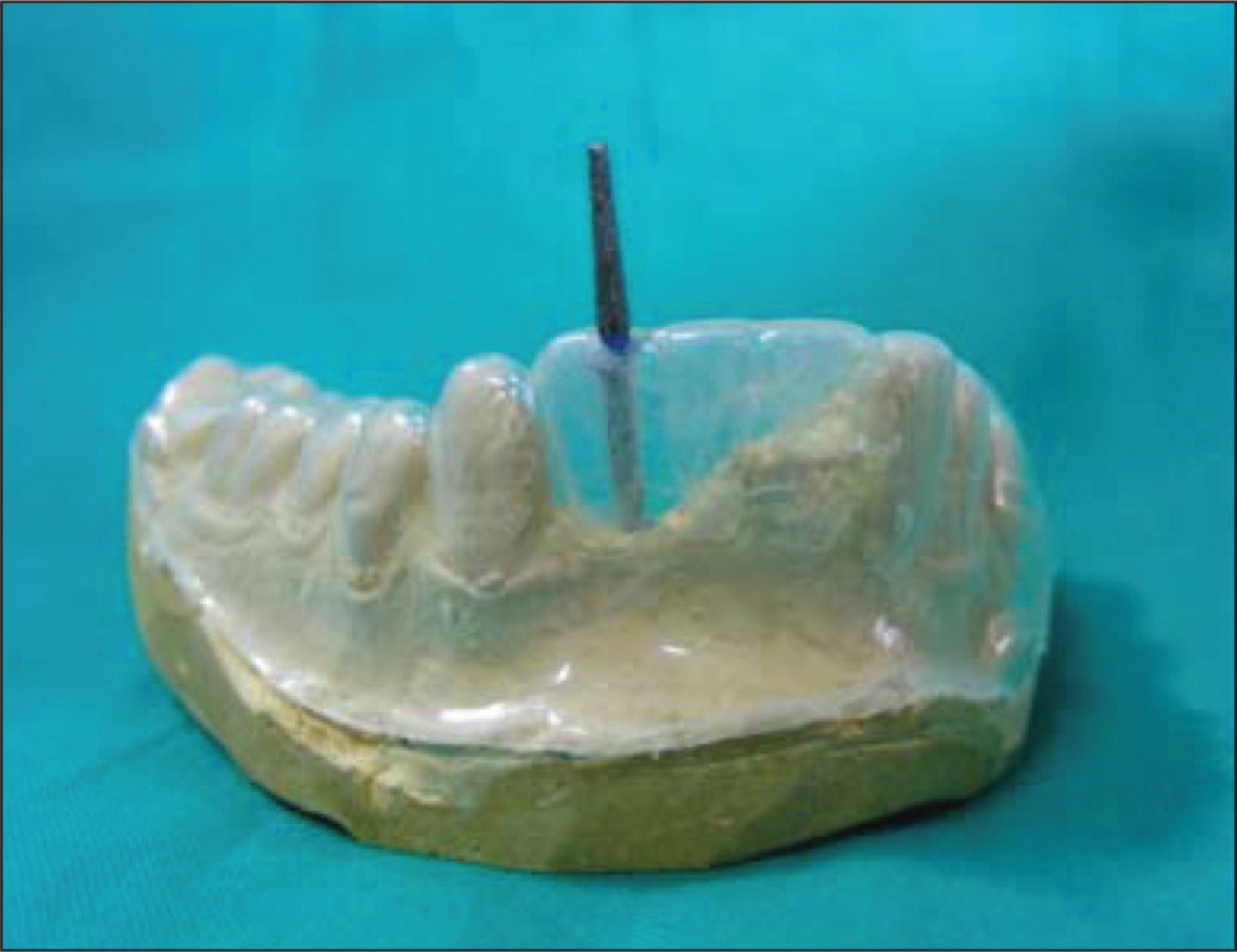
The angulation that the bur takes represents the angulation of the implant. Any change in angulation can be corrected if required. A surveyor may also be used by replacing the bur with analyzing rod and for verification of angulation.
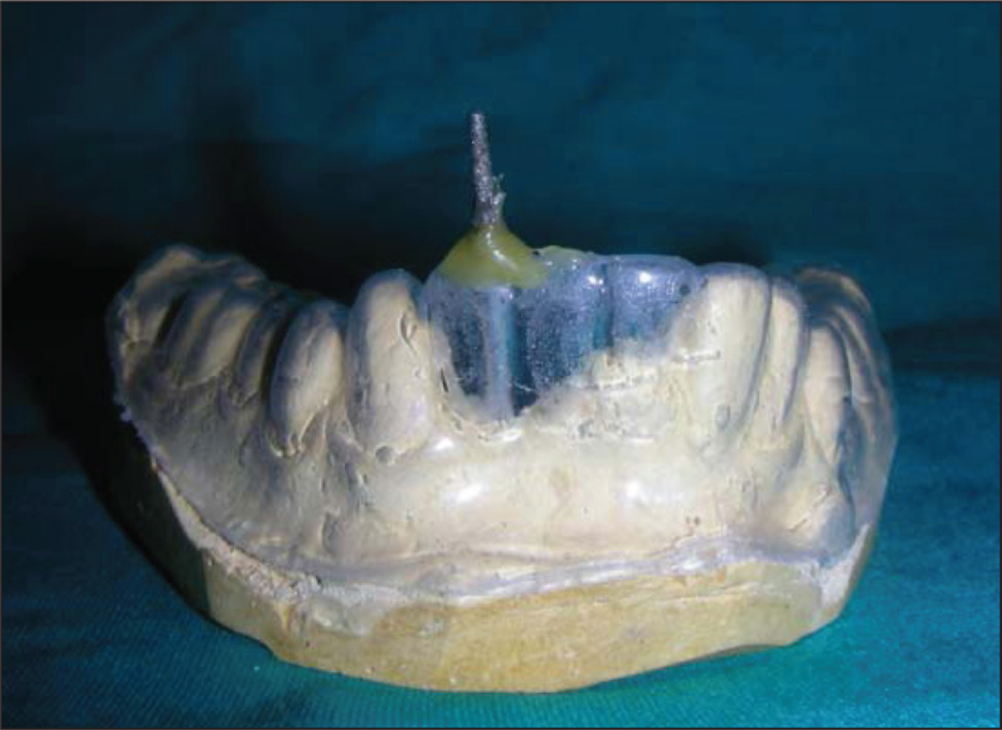
Once the angulation was verified, sticky wax was used to stabilize the metal bur (Figure 6).
Sticky Wax Used to Stabilize the Metallic Bur
A thin layer of separating medium was applied onto the metallic bur that was positioned within the vacuum formed template.
A thin, bubble-free mix of clear acrylic autopoly-merizing resin (DPI-RR cold cure acrylic resin) was loaded into the template containing the metallic bur. The template was then placed on the master cast. The position of the metal bur was adjusted so that the 2 reference points were correctly aligned. This was verified by the seating of the metallic bur in the hole drilled at the first reference point on the master cast.
After the polymerization was complete, the vacuum-formed template was removed first. The angulation was reverified by taking an intraoral radiograph with the stent and the bur.
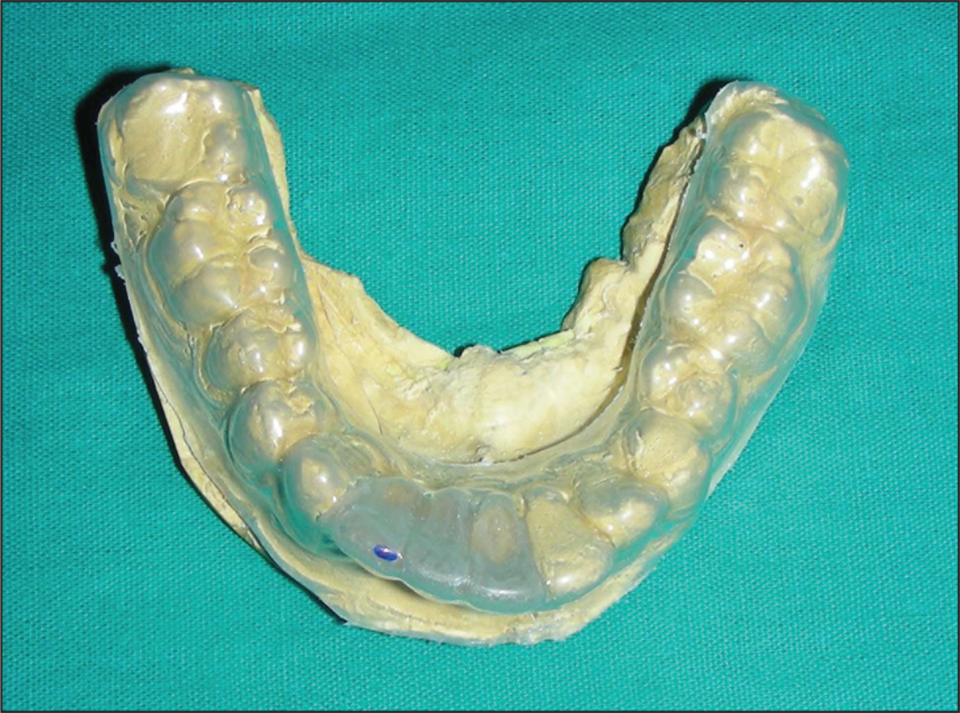
The bur was removed with the help of pliers. The stent was finished, polished (Figure 7), and disinfected by the cold sterilization method (using 2% glutaraldehyde solution for 20 minutes) and tried intraorally.
Clear Acrylic Stent
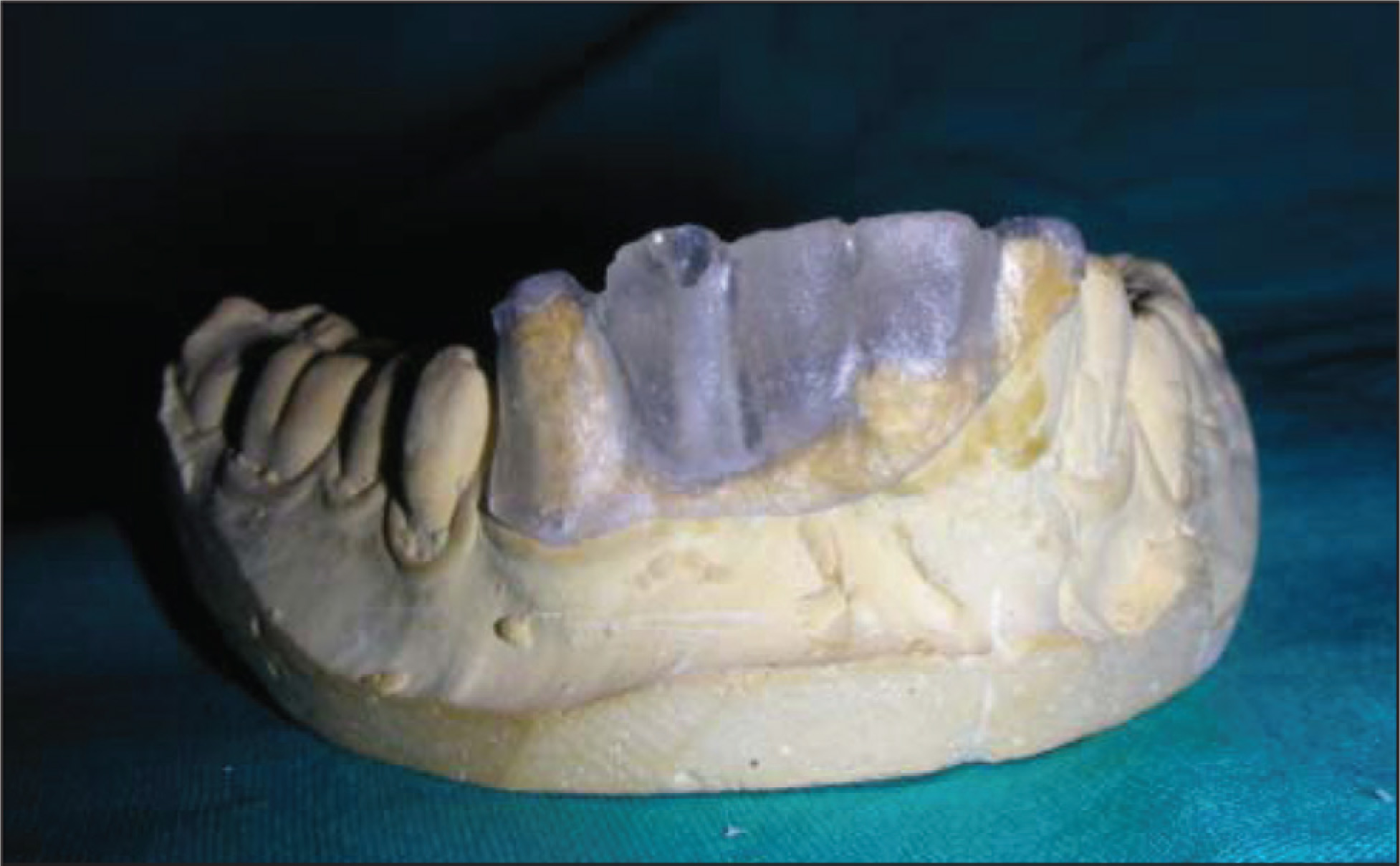
The 2-mm bur corresponded to the pilot drill of the Alpha Bio implant system. The canal formed can be enlarged depending on the implant diameter.
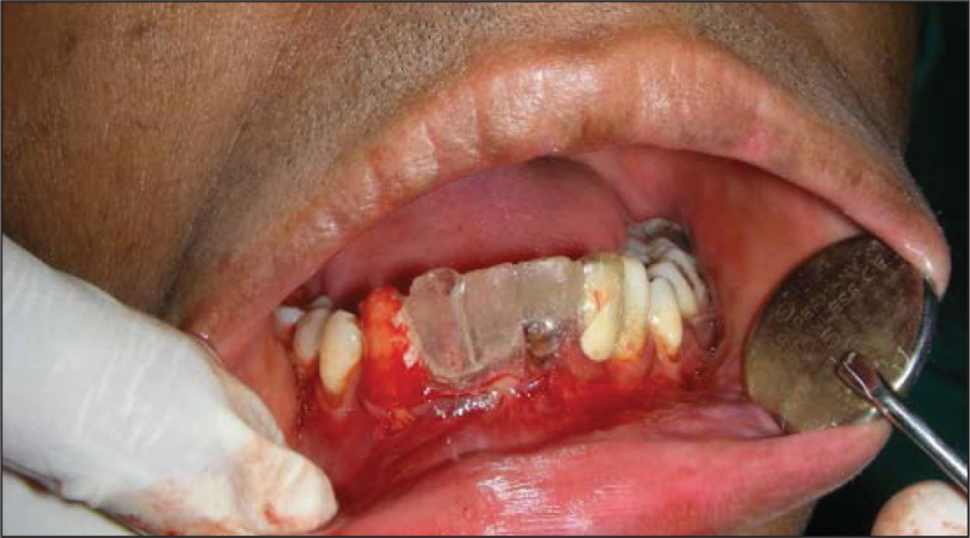
The stent fabricated was sterilized again using the cold sterilization technique (2% glutaraldehyde for 20 minutes) and then used during the implant surgery (Figure 8).
Surgical Stent Used During Implant Placement
Discussion
To establish continuity between diagnosis, treatment planning, and surgical phases, the use of a surgical stent is necessary. Ideally, stent should be stable, rigid, proper size, transparent, surgically aseptic, and be able to undergo revision if needed. It should allow the bony ridges and the drills to be visualized and the template should relate to the ideal facial contour. 10
Various methods for the fabrication of stents have been discussed by various authors 11 : Autopolymerizing acrylic resin material was used with metal bearings (Engelman et al), 1-mm metal pins (Cehreli et al), orthodontic wire, stainless steel ball, gutta-percha points (Koyanagi), barium sulfate liquid coat over thin orthodontic wire (Kopp et al), silicone impression material (Tsuchida et al), titanium cylinders (Annibali et al) as radiographic markers. The vacuum-formed thermoplastic matrix or customized acrylic tray was used with various radiographic markers such as gutta percha (Pesun and Gardner), stainless steel tubes (Takeshita et al), brass tubes (Becker and Kaiser), lead strip (Almog et al), etc. The use of lead strips for the fabrication of the stent may result in an unacceptable implant placement of the access hole and angulation. The use of gutta-percha in the fabrication of the stent may act as both surgical and radiographic guide. It allows proper angulation of the implant only if the location of the access hole of the implant is not altered. The use of a metal sleeve guide allows more precise placement acting as both radiographic and surgical guide. 3 However, in case of any change of angulation after the diagnostic imaging, the stent has to be remade with the repositioning of the sleeve in a different direction. The availability and cost of the metal sleeves/brass tubes also need to be considered. The use of set-up disks also gets limited with its availability in required dimensions.
The technique described makes use of readily available materials. It also fulfills the ideal requirements of a surgical guide mentioned above. The stent can be used both as a radiographic and surgical guide. It can be modified to be used for larger diameter implants by progressively increasing the size of the drill hole with larger diameter drills. A limitation of this technique is that distortion of the wax pattern or shrinkage of cured acrylic resin can affect the precise angulation during implant placement. In advantages, this technique is simple, economical, and accurate as compared with other techniques available and can be helpful for the placement of mini or regular implants
Summary
This article describes a procedure for constructing a surgical guide for the proper placement of mini-implants. It can also be used as a radiographic guide and can be modified to be used for larger diameter implants. The procedure is simple and makes use of readily available materials, and the guide fabricated fulfills the ideal requirements of a stent.
Footnotes
Declaration of Conflicting Interests
The authors declared no potential conflicts of interest with respect to the research, authorship, and/or publication of this article.
Funding
The authors received no financial support for the research, authorship, and/or publication of this article.