
Abstract
Accurate mini-implant placement in orthodontics is critical for ensuring good anchorage stability and preventing root damage. Conventional freehand insertion techniques often result in angulation errors, compromising treatment outcomes. This article introduces the Anguloguide, a novel tool designed to aid in both site determination and angular guidance during mini-implant placement. The Anguloguide is fabricated using 0.019 × 0.025-inch stainless-steel wire, an expansion screw, and an acrylic component. It incorporates a radiopaque marker for imaging and a negative impression of the mini-implant driver to guide precise insertion. The expansion screw enables vertical height adjustment, while the wire framework provides fixed angulation. The guide remains in position throughout the procedure, ensuring consistent accuracy. Unlike conventional stents, which assist only during initial site identification, the Anguloguide allows for real-time angular control without removal. It reduces operator-dependent variability and chairside time. The Anguloguide offers a cost-effective and easily fabricated solution for improving the precision of mini-implant placement. Its dual functionality in site localization and angulation guidance enhances both efficiency and safety in orthodontic procedures.
Introduction
Mini-implants have transformed orthodontic practice by enabling temporary skeletal anchorage and controlled tooth movement, reducing dependence on patient compliance and extraoral appliances.1, 2 However, precise site selection and angulation remain critical for successful mini-implant insertion, as inaccuracies can lead to complications such as root damage, instability, and soft-tissue irritation.3, 4
Freehand placement, though commonly used, is associated with operator-dependent variability and the potential for angulation errors.5, 6 To overcome these challenges, several guiding systems have been developed; however, many only aid in site determination and must be removed before insertion, risking deviations in the final placement.7, 8 Digital and stereolithographic guides improve precision but require extensive planning and resources.9, 10
The Anguloguide was designed as an innovative, cost-effective, wire-based appliance that combines site determination and angular guidance in a single unit. This manuscript describes its design, fabrication, and application, and discusses its relevance in enhancing procedural accuracy, reducing clinical chairside time, and improving patient outcomes.
Description of the Technique
The Anguloguide is a wire-based chairside appliance developed to provide combined vertical and angular guidance during orthodontic mini-implant placement. It aims to enhance insertion precision by integrating both site determination and angulation control into a single, user-friendly guide.
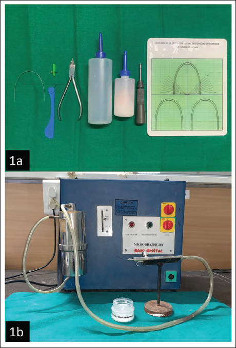
Materials Required (Figure 1a, 1b)
0.019 × 0.025 stainless-steel wire
Expansion screw
Bird beak plier
Monomer and polymer
Mini-implant driver
Angle-measuring grid
Soldering unit
(a) 0.019 × 0.025 Stainless-steel Wire, Expansion Screw, Bird Beak Plier Monomer and Polymer, Mini-implant Driver, Angle Measuring Grid. (b) Soldering Unit.
Fabrication Process
Wire preparation and soldering
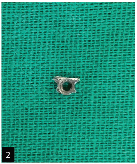
a. The expansion screw consists of a central screw mechanism with stainless-steel components on both sides.
b. Remove these stainless-steel components to reveal three preformed holes.
c. Trim away the two outer holes, retaining only the central hole through which the screw passes (Figure 2).
d. Bend a 0.019 × 0.025 stainless-steel wire into a sharp U-shaped loop.
e. Solder the 0.019 × 0.025-inch stainless-steel wire on the flat upper surface of the modified stainless-steel component, ensuring the U-loop is perpendicular to the screw axis. This configuration ensures stability and does not interfere with screw mechanics.
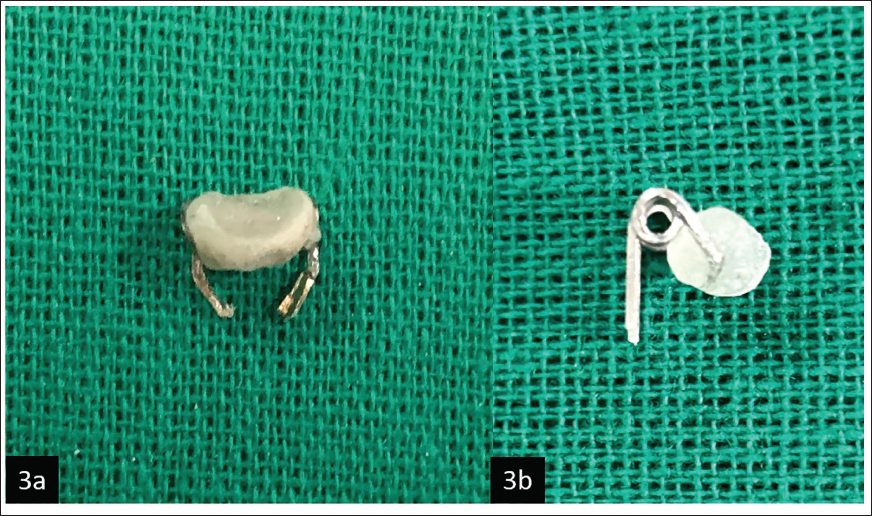
Helix formation and support arm (Figure 3a)
a. Cut a segment of 0.019 × 0.025 stainless-steel wire and form a helix using a bird beak plier. Ensure the helix is angled at 45° relative to the vertical axis of the guide, as verified using an angle-measuring grid. This alignment facilitates ideal implant angulation with respect to bone and adjacent roots.
b. To shape the support arm, bend one end of the helix at a 90° angle to create a horizontal extension. This extension will act as a base to support the acrylic component and should be extended till it has enough width to support the mini-screwdriver head.
c. After setting the desired width, bend the wire again at a 90° angle and then shape it into another helix, such that the wire should align and overlap when viewed from the side, providing a stable structure to support the acrylic guide (Figure 3b).
d. The free ends of the helix can be bent inward to be soldered onto the sides of the modified stainless-steel component.
Acrylic component
a. The horizontal support arm between the two helices serves as the base for the acrylic component. Apply acrylic over this area.
b. Before the acrylic sets, embed a small piece of stainless-steel wire at the center of the acrylic. This embedded wire will be visible on radiographs, allowing precise identification of the midpoint to locate the area for mini-implant placement.
c. While the acrylic is still pliable, the head of a mini-implant driver is pressed into it to form a negative imprint. The driver is then positioned at a standardized 45° angle using an external angle-measuring grid, which serves as a reference for angulation. The angle grid is held in place during acrylic setting to preserve the intended orientation.
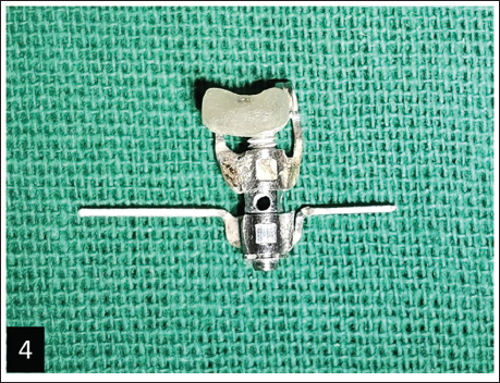
Assembly and finalization
a. The free ends of the helix are soldered to the modified stainless-steel component.
b. Polish the acrylic to eliminate sharp edges, enhancing patient safety and comfort.
c. The completed Anguloguide assembly (Figure 4).
Modification of the Stainless-steel Component by Removing the Outer Holes and Preserving the Central Hole for Screw Passage.
(a) Frontal View of Support Arm with Acrylic Component. (b) Lateral View of Support Arm with Acrylic Component Showing the 45° Angle Relative to Vertical Axis.
Completed Anguloguide Assembly.
Clinical Application
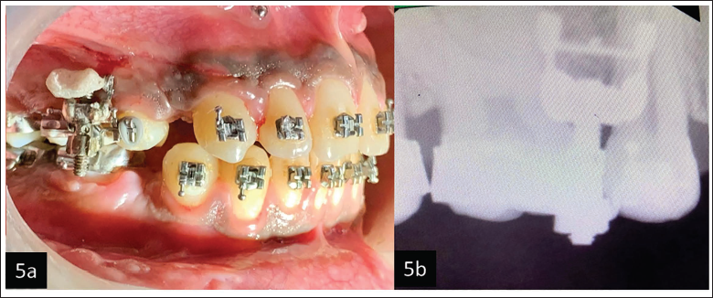
Insert the 0.019 × 0.025 stainless-steel wire into the molar and premolar tubes. Secure the wire firmly to ensure stability during the procedure (Figure 5a).
The embedded stainless-steel marker in the acrylic component acts as a guide for locating the mini-implant placement area through radiovisiography (RVG) (Figure 5b).
Adjust the vertical height using the expansion screw key for site selection.
Confirm the site using RVG.
Lidocaine will be administered to anesthetize the gingival tissues.
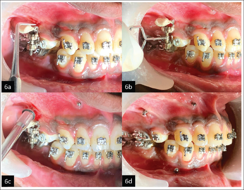
Use a probe to create a bleeding point at the confirmed mini-implant placement site (Figure 6a).
Adjust the expansion screw as needed to align the acrylic component and driver head with the bleeding point (Figure 6b).
Ensure the mini-implant driver rests securely within the acrylic component.
Load the mini-implant into the driver. Insert the implant while using the guide to maintain a consistent 45° angulation. The Anguloguide ensures precision by stabilizing the driver and maintaining the desired insertion angle (Figure 6c).
Unsecure and carefully remove the Anguloguide after successful insertion of the mini-implant (Figure 6d).
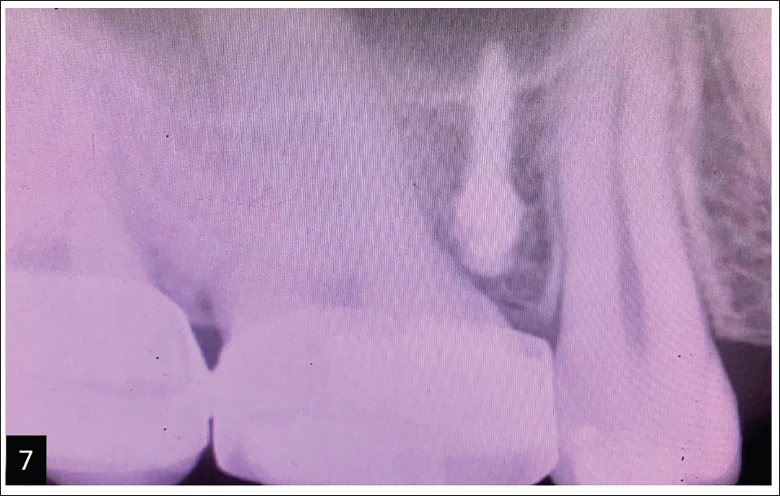
Take an RVG to confirm the mini-implant’s position in the interradicular bone and verify that the roots remain undamaged (Figure 7).
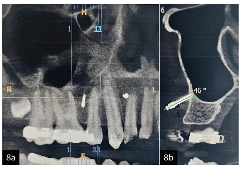
A cone-beam computed tomography (CBCT) report demonstrates accurate positioning of the mini-implant without contacting the adjacent tooth roots (Figure 8a) and achieving a close-to-ideal angulation (Figure 8b).
(a) Anguloguide is Stabilized in Position. (b) Embedded Stainless-steel Marker in the Acrylic Component Helps in Site Conformation Using Radiovisiography (RVG).
(a) Probe Being Used to Create Bleeding Point. (b) Vertical Adjustments Being Made Using the Expansion Screw Key. (c) Driver’s Head is Stabilized During Insertion of Mini-implant. (d) Anguloguide is Removed After Implant Insertion.
Confirmation of Implant Site Using Radiovisiography (RVG).
(a) Cone-beam Computed Tomography (CBCT) Report Demonstrates Accurate Positioning of the Mini-implant Without Contacting the Adjacent Tooth Roots. (b) CBCT Report Demonstrates Close to Ideal Angulation of the Mini-implant.
Advantages
Dual functionality: The Anguloguide combines site determination and angulation assistance into a single tool, enabling precise mini-implant placement without removing the guide.
Adjustable vertical precision: The expansion screw can be opened or closed to adjust the guide to the desired vertical height with millimeter-level precision, ensuring accurate implant placement in the area of interest.
Angular guidance: The wire-bending component, incorporating a helix, provides reliable angular guidance. The system allows customization of the angulation, enabling the desired implant placement angle to be integrated seamlessly.
Continuous guidance: Unlike traditional guides, the Anguloguide remains in place throughout the procedure, ensuring consistent site and angulation guidance from start to finish.
Improved accuracy: By combining vertical, angular, and site determination in one tool, the Anguloguide enhances accuracy in mini-implant placement, improving clinical outcomes.
Enhanced safety and comfort: The stability provided by the expansion screw and wire components ensures secure handling during the procedure, enhancing patient safety and comfort.
Disadvantages and Limitations
Technique-sensitive fabrication: The fabrication process requires precise wire bending, soldering, and adaptation to individual arch forms, which may vary in quality depending on the operator’s skill.
Limited commercial standardization: As a chairside-fabricated device, Anguloguide currently lacks commercial standardization. Its compatibility may vary across different mini-implant driver designs and brands, which could affect uniform clinical application.
Anatomical adaptability: The current design does not incorporate patient-specific anatomical variables such as cortical bone thickness, soft tissue biotype, or root divergence. This could influence ideal implant positioning, especially in complex or posterior sites.
Partial stabilization of guide head: While the guide provides directional control, the head of the Anguloguide is not fully stabilized in all dimensions during implant insertion. Minor intraoperative movement may occur, particularly in less accessible regions.
Absence of longitudinal or comparative validation: No extensive in vivo or typodont-based studies have yet been conducted to assess accuracy, user variability, or clinical success rates across a broad population. These aspects remain an important focus for future research.
Discussion
Accurate placement of mini-implants is a cornerstone for achieving predictable anchorage in modern orthodontics. However, freehand insertion techniques, though commonly used, are inherently prone to operator error, particularly in maintaining optimal angulation and avoiding root proximity.3, 6 These errors may contribute to failure rates as high as 13%, as noted in recent meta-analyses. 3
The Anguloguide aims to address these challenges by offering a practical solution that integrates both site determination and angular guidance into a single tool. By providing real-time directional control during insertion, it minimizes deviations from the planned implant trajectory. This is especially relevant given the findings of Suzuki et al., 10 who demonstrated improved accuracy and reduced angular deviation when 3D-printed surgical guides were used. However, such digital methods often demand specialized planning software, lab fabrication time, and higher cost barriers that the Anguloguide effectively bypasses. Similarly, Wilmes et al. advocated for mechanical-guidance systems to reduce the risks of cortical perforation and root contact. 11 Supportive findings are further echoed by Liu et al., who emphasized the importance of angular accuracy in reducing implant micromovement and improving long-term success rates. 12 Kuroda et al. reported acceptable success rates with freehand insertion in skilled hands, highlighting that the operator’s experience plays a significant role. 13 Additionally, Kim et al. expressed concerns about overreliance on guides potentially limiting the development of tactile feedback and clinical judgment in young clinicians. 14
Conventional guides, such as stents or grids, typically assist only in locating the insertion site and are removed before actual insertion, risking angular deviation at the most critical phase. 8 In contrast, the Anguloguide remains engaged throughout, ensuring both vertical and angular consistency. Furthermore, the incorporation of a stainless-steel marker in the acrylic component permits radiographic confirmation of the insertion point, enhancing procedural reliability.
Anguloguide offers affordability, ease of fabrication, and chairside adaptability, making it a compelling alternative to computer-aided design (CAD)/computer-aided manufacturing (CAM) systems and 3D-printed guides. The tool may also serve as a valuable educational adjunct for postgraduate training, allowing consistent replication of mini-implant insertion mechanics and helping students develop spatial awareness for ideal angulation.
Looking ahead, integration with digital components such as intraoral scans and 3D-printed acrylic modules may enhance the tool’s versatility and precision. Comparative clinical trials evaluating implant success rates, patient-reported outcomes, and procedural efficiency could provide further validation. In summary, the Anguloguide presents a low-cost, effective, and reproducible method to standardize mini-implant placement. Its impact may extend beyond individual case success, contributing to safer practices, fewer complications, and enhanced predictability in orthodontic anchorage mechanics.
Conclusion
The Anguloguide is a novel orthodontic device designed to speed up and increase the accuracy of micro-implant insertion. It delivers optimal insertion by combining site identification and angular guidance into a single tool, decreasing procedural complexity and chairside time. Its ability to provide consistent, real-time guidance from initial site selection to implant insertion is a significant step forward, contributing to safer treatments, improved clinical outcomes, and increased efficiency in orthodontic workflows.
Footnotes
Acknowledgment
The authors thank MIDSR Dental College for infrastructure and clinical support.
Declaration of Conflicting Interests
The authors declared no potential conflicts of interest with respect to the research, authorship, and/or publication of this article.
Ethical Approval
Ethical approval was not required for this article as it does not involve experimental procedures, patient interventions, or data from multiple human participants.
Funding
The authors received no financial support for the research, authorship, and/or publication of this article.
Informed Consent
Written informed consent was obtained from the participant for the use of their information and photographs featured in this article.