
Abstract
Modern business process management (BPM) is increasingly interesting for laboratory automation. End-to-end workflow automation and improved top-level systems integration for information technology (IT) and automation systems are especially prominent objectives. With the ISO Standard Business Process Model and Notation (BPMN) 2.X, a system-independent and interdisciplinary accepted graphical process control notation is provided, allowing process analysis, while also being executable. The transfer of BPM solutions to structured laboratory automation places novel demands, for example, concerning the real-time-critical process and systems integration. The article discusses the potential of laboratory execution systems (LESs) for an easier implementation of the business process management system (BPMS) in hierarchical laboratory automation. In particular, complex application scenarios, including long process chains based on, for example, several distributed automation islands and mobile laboratory robots for a material transport, are difficult to handle in BPMSs. The presented approach deals with the displacement of workflow control tasks into life science specialized LESs, the reduction of numerous different interfaces between BPMSs and subsystems, and the simplification of complex process modelings. Thus, the integration effort for complex laboratory workflows can be significantly reduced for strictly structured automation solutions. An example application, consisting of a mixture of manual and automated subprocesses, is demonstrated by the presented BPMS-LES approach.
Keywords
Introduction
The field of life science automation (LSA) deals with automation solutions in a wide range of laboratory applications, for example, medicine, pharmacy, biology, and chemistry. Compared with manufacturing solutions, the process integration and automation level is often low. The focus for LSA solutions is still on distributed and separated systems (e.g., workstations and single instruments), which are controlled by process control systems (PCSs) or scheduling systems such as SAMI EX, VWorks, Microlab VENUS, and Clarity, 1 or instrument-specific vendor software. So-called integrated systems combine different workstations with required instruments of different complexities (e.g., readers, shaking/tilting devices, or incubators) by local transport robot solutions, 2 for example, the TX and TS series (Stäubli International AG, Pfäffikon, Switzerland), the Motoman MH series (Yaskawa Electric Corporation, Kitakyushu, Japan), or the KR Agilus CR series (KUKA Roboter GmbH, Augsburg, Bavaria, Germany). This combination extends the application range, increases the automation level, and offers more complex continuous automated processes.
The current developments for laboratory automation systems are focused on the combination of instruments, workstations, and integrated systems with complex automation systems. The particular challenge lies in the special separation of the devices and systems spread over the laboratories of the institution building. This aggregation requires the implementation of flexible mobile transport solutions to cover paths, including the doors and elevators, between the devices and systems. In this field, the market is still weak, especially when active pick-and-place procedures are required. Examples for that are KUKA Mobile Robotics iiwa (KUKA Roboter GmbH), H20 (Dr. Robot) as shown in Liu et al., 3 and partially the Adept Lynx Platform (Adept Technology GmbH, San Ramon, CA).
The new level in laboratory automation needs a superordinated control system as a logical consequence, which allows the planning, scheduling, and execution of more complex automation processes. This requires sufficient access to the implemented subsystems (as instruments, workstations, and integrated systems) through their PCSs, scheduling systems, and instrument control systems (ICSs) to prepare and execute system-specific methods, procedures, and functions. Moreover, the control system for the mobile transportation units needs to be implemented to combine the subsystems and to permit more complex workflows. In general, workflow-oriented process management systems (PMSs), manufacturing execution systems (MESs), or laboratory execution systems (LESs, a specific form of the MES) are used to perform these complex processes (see Fig. 1 ).
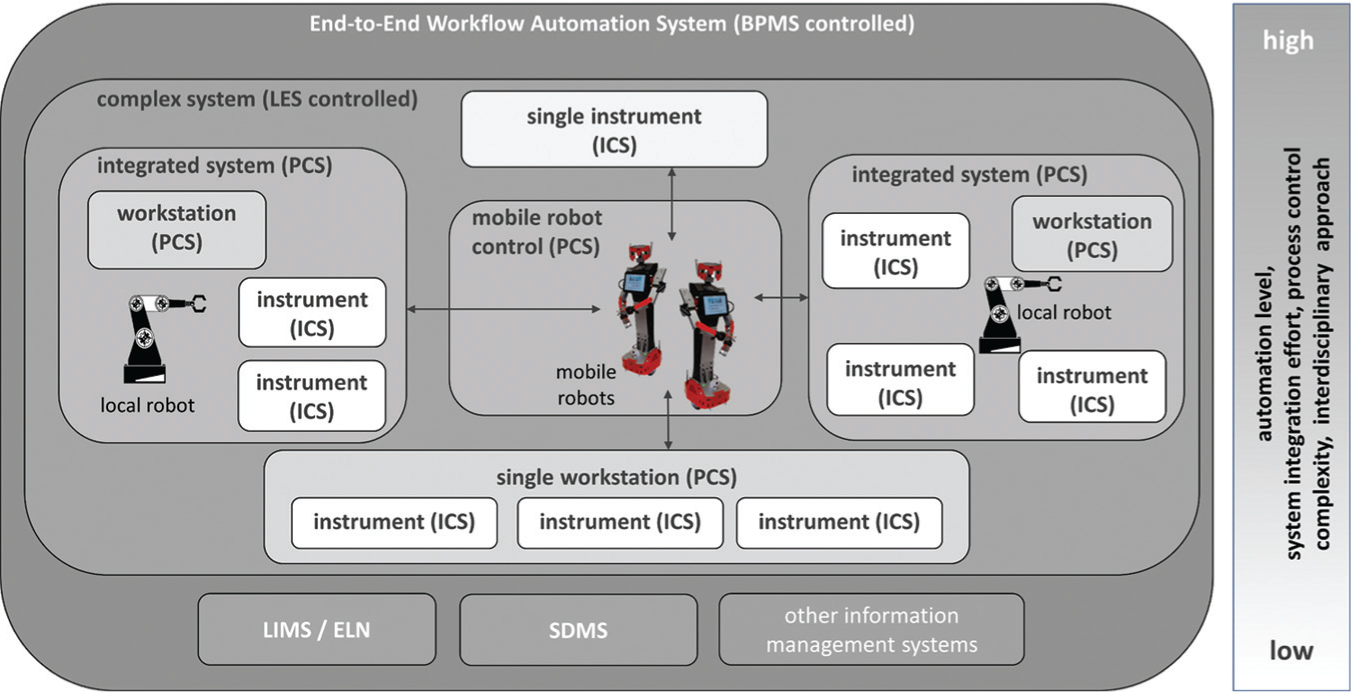
BPMS approach in LSA. The novel generation of LES simplifies the automated chaining of instruments, workstations, and integrated systems by mobile robots. The gray level indicates the different hierarchical automation level.
When LESs themselves do not provide appropriate process documentation, master data management, measurement data acquisition and processing, sample tracking, process template management, and report and documentation management,4–8 they require additional IT system integrations, for example, laboratory information management systems (LIMSs), 9 electronic laboratory notebooks (ELNs),10,11 or scientific data management systems (SDMSs). 12
Business Process Management Meets Laboratory Automation
A new approach in LSA is the implementation of business process management systems (BPMSs) for the standard-driven workflow automation. According to a study conducted in Germany, the dissemination of BPMSs, especially in larger life science organizations, is rather high, with 96% (n = 48), although only a small part of the offered functionalities are used so far. 13 The general concept of business process management (BPM) is spread in the four base phases: modeling, execution, monitoring, and optimization. These phases are arranged in the so-called BPM life cycle and run through continuously to optimize a planned process. 14 In practice, only 30% of the companies have a close connection between their operational information technology (IT) systems and their process models. Consequently, only 17% of the companies use BPM tools for IT-supported executions, 13 whereby the execution primarily refers to manual processing steps. However, in general, increasing usage and improved satisfaction concerning the management quality and achievement were recorded. 13
Previously, for example, the event-driven process chain (EPC) and Business Process Model and Notation 1.0 (BPMN 1.0) were used for the modeling of business processes. 15 Since the introduction of BPMN 2.0 and its elevation to an international standard (ISO/IEC 19510:2013) for business process modeling, 16 most BPMS have developers switched to it. The main advantages of BPMN 2.0 are the compatibility between different planning editors and process engines for executable process models 17 and—due to the use of the same notation—a common basis of understanding between IT and the automation engineers, business process experts, and process applicants.
The BPMN process diagram permits the creation of almost arbitrary workflows, which consist of logically coupled activities and subprocesses, including the necessary handling of data, dependencies, and connections (e.g., process variables and their decisions; the human operators and their role; interface information, e.g., web services, input/output [I/O] data handling, and their mapping to process data; and interface provision for user–machine and external systems interactions). The resulting benefit of the BPM concept in LSA is the possibility to handle so-called end-to-end processes, which cover the overall process steps from their beginning (e.g., sample entry or system/process preparation) to their end (e.g., cleaning and recycling procedures, sending results to customers, and process data archiving), irrespective of whether a human or machine executes the task or the task size and complexity (see Fig. 1 ). The implementation of human operators especially constitutes interesting perspectives for the LSA due to the fact that manual processing steps (in BPMN, referred to as human tasks) around an automated environment can also be integrated.
Experiences with BPM in Hierarchically Structured Laboratory Automation
The application potential of BPM in the field of LSA has been investigated and published in several years of research work, which supports the argumentation of this contribution in general. The aim of this research was the junction of classical laboratory automation with the BPM approach to establish a novel top-level workflow automation on the basis of the BPMN 2.0 standard. At an early stage, the achievement potential of human task automation by BPMS for the life science industry became clear. With this functionality, manual operations can be considered in global process control, which often form the link between automated subprocesses or comprise extensive pre- and postprocessing phases, respectively. The human task support achieved by BPMS supplements the established laboratory automation by the ability to depict (independent of the degree of automation) end-to-end processes and coherently support and monitor them. Already investigated significant advantages of the human task supports are error reduction and quality assurance, especially for time-critical process chains. 18
The use of BPMN 2.0 for process modeling in laboratory automation obtains a higher flexibility for professional users due to their direct involvement in the development and testing process of BPMS solutions. Simulation solutions, which depict the overall process with all its automation components, service tasks of data processing, and manual procedures, can effectively support the interdisciplinary development and test process. 19 Furthermore, it becomes apparent that in contrast to the usual BPM applications of business informatics, BPMN 2.0 can be regarded as a novel automation language for arbitrarily hierarchically structured automation components. This automation language includes, although not obligatory, full automation in service-oriented networks, whereby the laboratory automation components are provided as service tasks. Göde et al. 20 described the integration of BPMSs in the hierarchical laboratory automation using LIMSs as a generic recording platform for process data. Case studies of loosely coupled typical laboratory automation components validate the meaning and efficiency of the BPMS-controlled end-to-end-workflow automation. In this context, attention was drawn to the present situation of different (executable) process notations, which are distributed over at least three hierarchical automation levels (BPMSs, PCSs, and ICS control). In addition, an increased rise of process-oriented solutions for laboratory data processing (e.g., LIMSs) can be noticed, which also introduces its own process control languages for subworkflows.4,8
The synergy potential of BPMSs and generic information management solutions, for example, LIMSs and ELNs, was also investigated. For every process run (instance) caused by the variable process workflow control of the BPMS, individual process results and execution data occur, which should be recorded automatically as far as possible. Especially on the workflow automation level, implemented end-to-end processes require extensive process execution documentation, which takes into account process models and process data as important factors for the reproducibility of processes and as a point of departure for the quality assurance and proof. Both extent and high variability of the workflows to be automated generate a high number of changeable process variables and process statuses, which require a generic approach for the information management of process instances. Accordingly, the long-established LIMSs and ELNs offer extensive possibilities of process data recording and can be combined with BPMSs, as shown by Holzmüller-Laue et al. 21
The typical hybrid and heterogeneous automation environment of the LSA requires a high effort for systems integration. Therefore, solutions of efficient vertical and horizontal systems integration have to be developed. This includes the integration of different existing IT solutions (e.g., LIMSs, ELNs, chromatography data systems [CDSs], safety data sheets [SDSs], SDMSs, MESs, and spreadsheet application) on the workflow level in BPMSs as automation components. Special cases of horizontal systems integration are across-company or across-organization e-business applications, which are particularly interesting for consistent quality assurance. Holzmüller-Laue et al. 22 referred to typical integration tasks for LSA examples, whereby the limits of process complexity in BPMSs and problems concerning real-time demands also became visible.
The listed investigations offer an extensive consideration of the transfer of BPM into the application field of laboratory automation. As a result, the significant conclusion regarding the use of BPM in laboratory automation can be summarized as follows (in consideration of the fact that not every BPMS contains a sufficient range of functions):
BPMSs enable a novel top-level control of automation components.
BPMSs offer the implementation of human task support in automation chains.
BPMSs depict end-to-end processes at the workflow automation layer.
BPMSs conflate tasks of professional users, IT experts, and process automation engineers.
BPMN 2.0 can be considered a novel executable top-level automation language.
BPMSs support service-orientated architectures (SOAs)23,24 and database access.
BPMSs offer an open vertical and horizontal systems integration, which can be organized in an across-company manner.
BPMSs offer a standard interface concept (connectors) for the implementation of arbitrary subsystems and processing services.
BPMSs offer direct access to all subordinated SOA components in the hierarchically structured laboratory automation up to the field layer (intelligent sensors/actuators).
Generic LIMS and ELN solutions or other external information systems are required for master data management and for recording of process instance data generated by each workflow execution.
BPMSs implement data flow control by interfaces (process database access and service calls) to arbitrary data stores. In BPMN 2.0, the data flow is part of the process model and can be combined with professional standards such as ASTM/Analytical Information Markup Language (AnIML).
BPMSs are less appropriate for the control of real-time dependent or specific processes due to their open and interdisciplinary concept.
In addition to the executable process model, the exploitation of BPM for end-to-end workflow automation in life sciences comprises four important partial solutions (see Fig. 2 ). The already treated investigations of BPMS solutions 1–3 (in Fig. 2 ) were extensively discussed by Holzmüller-Laue et al.18,21,22,25 The approach of Holzmüller-Laue et al. used a centralized BPMS-controlled structure, which controls all subsystems and appropriately requires an overall systems integration in BPMSs (see Fig. 3 , concept 1). In contrast to that approach, the current investigations (see Fig. 2 , no. 4) deal with the coupling of distributed subworkflow controllers, located on the workflow automation layer, with the BPMS. This implies the displacement of workflow control tasks to capable and more specialized subsystems, which consequently also affects the displacement of the systems integrations to the subsystems (see Fig. 3 , concept 2). In consideration of the introduced preliminary work, this article discusses the introduction of a BPMS-LES approach, distribution conditions, and an application focus.
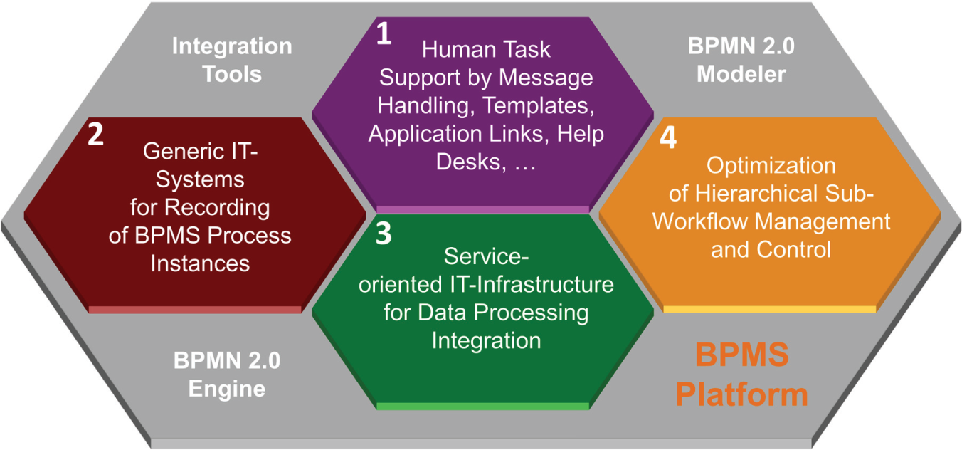
Four partial investigations for applying BPMS in LSA.
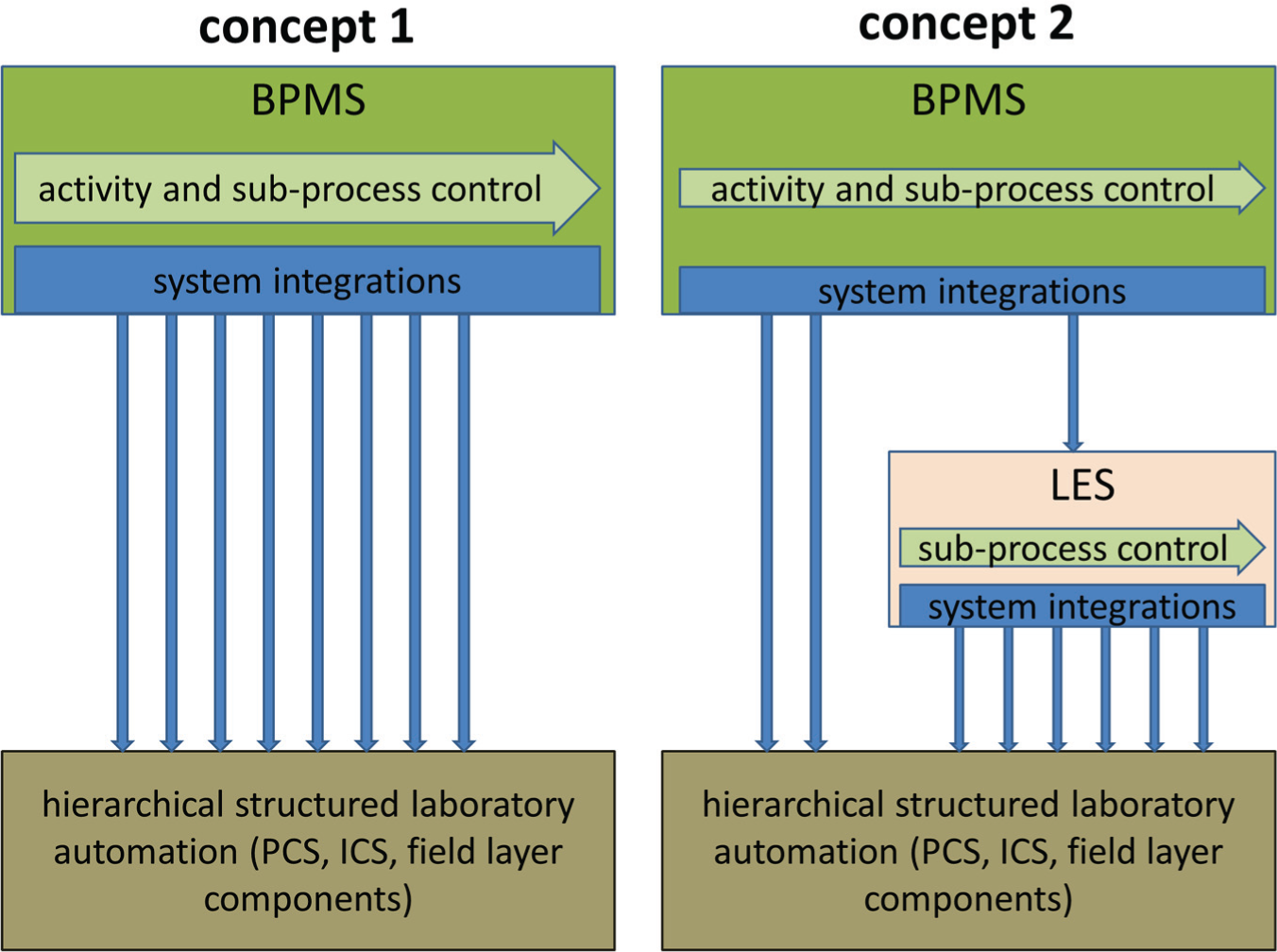
Concept comparison for the BPMS approach shows the simplification effect concerning the subprocess control and system integration at the BPMS level by using an LES.
Necessity to Comply with Hierarchical Structures of Laboratory Automation
As presented in the introduced research work, the implementation of BPMSs at the workflow automation level opens new beneficial possibilities in laboratory automation. Various processed applications were already performed, for example, drug screening in an environment with connected automation islands, as described by Holzmüller-Laue et al. 25 Thereby, the BPMN overall process modeling took place considering subsystems executed by PCSs. An unbound structure of the subsystems was assumed. This means that single systems of the hierarchical structured laboratory automation communicate directly with the BPMS, independent of their position (level). However, this strategy cannot simply be transferred to arbitrarily complex and time-critical process chains. This applies particularly when complex laboratory processes demand several close system couplings of distributed, heterogeneous automation systems (with many state variables to be evaluated) and frequently material status checks in the process flow (e.g., temperature, concentration, or sample analysis). In this case, the BPMN model loses its flexibility and transparency, since standard procedures in process control, for example, status polling and error handling, dominate the model.
Summarized, the application of BPM in laboratory automation is still hindered by the following factors:
Different interfaces of the subsystems
A large number of specific process status variables of automation components,
The individual, often complex error handling on the automation islands
A comparably time-critical and close system coupling
A high synchronization effort with other parallel processes
A large number of different system resources to be managed by BPMSs
Thus, the increasing complexity in the control structures of the BPMN greatly restricts important advantages of the BPMS concerning clarity, operability close to the user, and generally simple systems integration. The ability of the BPMS for direct control of all components of the hierarchical levels of the structured process automation should only be used in simple or special laboratory applications, as shown by Trigg. 5 The compliance of the hierarchical structure, and thus the well-distributed load over specialized subsystems, permits us to keep the control structures of the BPMN, with complex and often changing processes, controllable.
The direct involvement of many automation islands especially requires a high integration and control effort in the BPMS. The developments of so-called LESs, which already link automation islands, simplify BPMS solutions by realization of workflow controls of huge distributed subprocesses. Thereby control of complex subprocess chains and appropriate required systems integrations can be displaced to a process-specified LES. This close automation and process proximity is, for example, necessary if interactions with the subsystems on the process control level are required during the planning. These interactions deliver status information or scheduling results (which, e.g., determine handover positions for the labware between processing steps or allow the performance of a causality check of the process model before its execution) to the LES.
However, an LES does not work with a standardized diagram type for process planning and execution. While BPMSs use the BPMN 2.0 standard, for LESs, the use of, for example, material flow diagrams is appropriate, which depict the application-oriented labware transport on the respective path. Thus, the material flow diagram supports the desired specification of the LES by professional users, which offers a user-friendly platform for the planning and execution of already complex, highly automated laboratory subprocesses.
The consequent hierarchical structuring of the automation subprocesses and systems ensures a stronger decoupling of the BPMS in its system environment. This results in decreased detailing of BPMN process diagrams. Subsequently, a novel LES solution for standard-driven BPM-oriented laboratory automation will be presented, which permits a high flexibility of the LES-subordinated automation components and is, in contrast to BPMSs, specialized in real-time-critical, material-oriented processes.
LES for Efficient (Simplified) BPMS Couplings
An LES was developed and investigated at the Center for Life Science Automation (celisca), called HWMS (hierarchical workflow management system) according to its position in the hierarchically structured automation environment. The simplified architecture of the HWMS and its classification into the structured overall automation is shown in Figure 4 . The HWMS provides its own graphical planning editor, which chains the distributed subsystems to a complex automation process by means of a material flow diagram. In contrast to the BPMS, the HWMS allows interactions with the subsystems during the planning phase by web services to request planning-relevant information (e.g., scheduling results of the PCS and status information) and include it into the planning process. The planning results are stored in a machine-readable structure in the process database and executed by the process controller. The process controller schedules the processes to be executed 26 and triggers the required process steps/subprocesses (e.g., labware transport by mobile robots or method execution by an integrated system) in accordance with the scheduling results. The execution of the subprocesses takes place via control of the structured subsystems (e.g., PCSs, ICSs, and analytic devices) on the subordinated levels (process control and instrument control level). Thus, the configuration of the available subsystems depends on the specific application content. The architecture, shown in Figure 4 , divides the subsystems of the considered HWMS into two separate substructures. The first substructure ( Fig. 4 , on the left of the process control layer, in blue) treats the transport tasks between the laboratory locations (primary different automations island and storage locations) and allocates the tasks intelligently to mobile robots and the human operator. The human operators are integrated via smart phones and tablet computers, which allow task allocations by the transportation and assistance control system (TACS), as well as the local task management. The mobile robots are integrated over the robot remote center (RRC), which permits status data acquisition (e.g., battery status and position), task distribution, and path planning for available transportation units. The labware is transferred by the mobile robots between the defined transfer stations of the workflow. Due to their application between distributed automation islands, 3 the robots interact with the automation environment and human operators during the transfer. The second substructure ( Fig. 4 , on the right of the process control layer, in brown) implements the required PCS and ICS to control the automation islands. The process control adapter system (PCAS) consists of one integration module for every PCS or ICS. These modules follow the SOA concept and still offer the BPMS direct access. Besides the required requests for planning, the execution commands and status requests are always included. The automation chain that arises through the combination of the subprocesses is permanently monitored and controlled concerning resource availability, error detection, and synchronization of interdependent parallel processes. For its subprocesses, the LES ensures an independent error handling and recovery (e.g., repeated runs with exchanged resources). In accordance with the task distribution between LESs and BPMSs, the error handling and recovery are also divided. Should the LES be unable to solve the error, an event in the BPMS/BPMN is triggered, which initiates a superordinated error handling and recovery related to the workflow modeling (e.g., repeated runs of subprocesses of the LES and manual error handling by technicians).
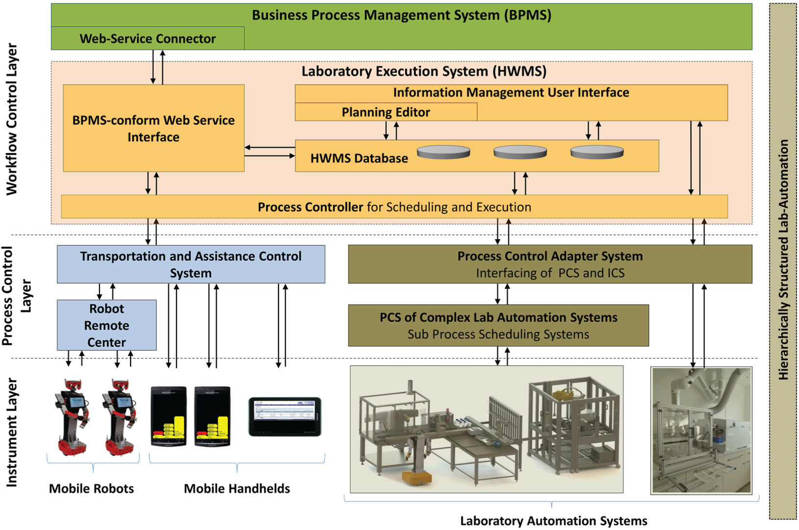
Structure and integration environment of the LES.
The integration of one or several LESs in a BPMS-oriented laboratory automation structure can be realized using standard-driven database interfaces or web services. By using databases, the LES offers read and/or write access for sections of the process database. The disadvantage of this solution, among others, is the high dependence of the BPMS on structural modifications in the LES database (changes in the LES database possibly require adaptions in the BPMS process model).
The preferred solution of using a web service module, as shown in Figure 4 , allows us to provide the range of functions of the LES by means of a standard protocol (mostly on the basis of the Hypertext Transfer Protocol [HTTP], Extensible Markup Language [XML], or JavaScript Object Notation [JSON]). Thus, structural changes in the LES database or in the LES architecture do not necessarily affect the BPMS process model, but then require the adaption of the web service, if necessary. Moreover, the web service allows the keeping of the defined registration procedures and the use of internal user management. Data access is primarily carried out over the database, whereby simple status or load distribution information can also be exchanged directly with the process controller.
The LES uses its an own process database and interfaces to external information management systems (e.g., PLSs, LIMSs, and analytical measurement systems) for recording data flows. In the presented systems solution for recording data flows of the LES, a generic LIMS 21 is used, which also provides the data for the BPMS. LIMSs increasingly support standards for the archiving and exchange of analytical data and metadata (AnIML standard), which easily can be implemented in BPMSs (e.g., call of AnIML-enabled viewers in human tasks).
Example Application
An example application illustrates the combination of BPMS and the introduced LES solution HWMS. The following workflows in the BPMS and HWMS were modeled and executed separately to show their general feasibility.
The example application deals with the determination of calcium (Ca) and phosphor (P) in bones using an inductively coupled plasma mass spectrometer (ICP-MS), as described by Fleischer et al. 27 The preparation and follow-up processing steps (e.g., tissue removal, bone crushing and drying, professional disposal, and data analysis) are manual processes that are logically controlled and monitored by the BPMS. Figure 5 shows the appropriate BPMN process model (simplified). The process model consists of the subprocess “Execution of LES-method” (shown simplified), which describes the integration of the LES web service, and thus the integration of complex subprocesses in the BPMN process model.
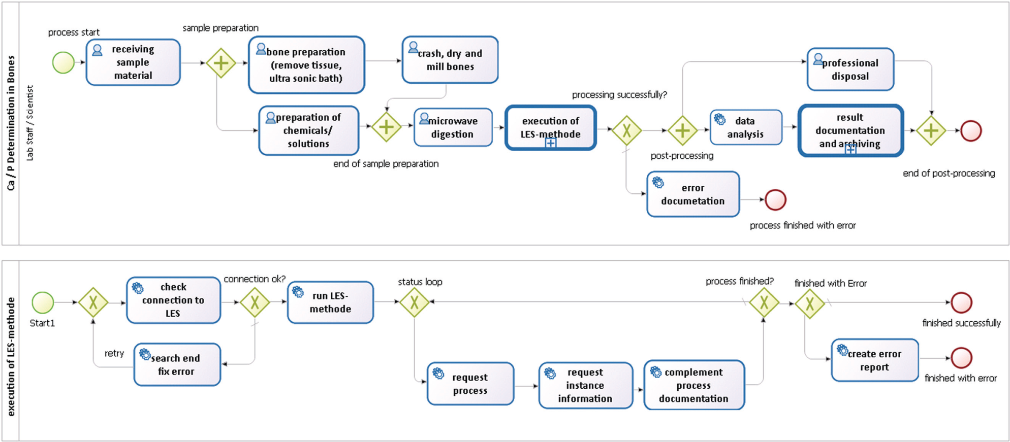
Simplified BPMN end-to-end process model for the example application, including the subprocess of the LES, called by a web service (below).
The complex subprocess is executed by the automation systems and is accordingly planned, controlled, and monitored in a method by the HWMS. Thus, the required systems integration, the interface control, and the management of the complex execution procedures from the BPMS are displaced to the HWMS. This also includes error handling, resource management, process scheduling/process synchronization, handling of process variables, and subsystem interfaces. The planned process chain consists of several transportation steps, which are executed by mobile transport robots or manually. Manual transport tasks to be executed are forwarded to implemented users via mobile handhelds. The process chains thus can be set up across laboratories and also across buildings.
In Figure 6 , the material flow diagram of the HWMS for the example application is shown. The process planning starts with the allocation of the initial positions for the required labware, whereby the position itself or the unique designation (ID) of the labware is used as a reference (see Fig. 6 [1]). The arrows (2) symbolize transportation tasks between the positions of the automation islands and transfer stations (inclusive initial and end positions). During the planning, these can be set at robot-based, human, or so-called dynamic transportation via a property window (5). The dynamic transport postpones the decision concerning the transport operator (robot/human) to the TACS (see Fig. 4 ), which distributes the transportation tasks in consideration of the available resources. The subprocesses of the automation islands (3) are controlled by a PCS or ICS and can also be configured by the property window. The definition of, for example, a PCS method in the process model allows the consideration of relevant process information from the PCS scheduling results (e.g., estimated process duration and number of labware paths, each inclusive of the user-specific labware path name, type, and expected labware starting position) for further process planning. Thus, in the example, the method “Serial Dilution” requires three different labware paths (dilution, sample, and tips), while the method “Anal. Meas. by ICP-MS” requires only one (sample). Every labware path contains different numbers of process-dependent labware units, which do not differ concerning labware type and labware content per path. After finishing the subprocess, the labware unit is treated appropriately for its path and transferred to the next automation island, a transfer station or the final position (4). During the process execution, the LES provides information about the process status, which also includes executing systems, devices, and operators.
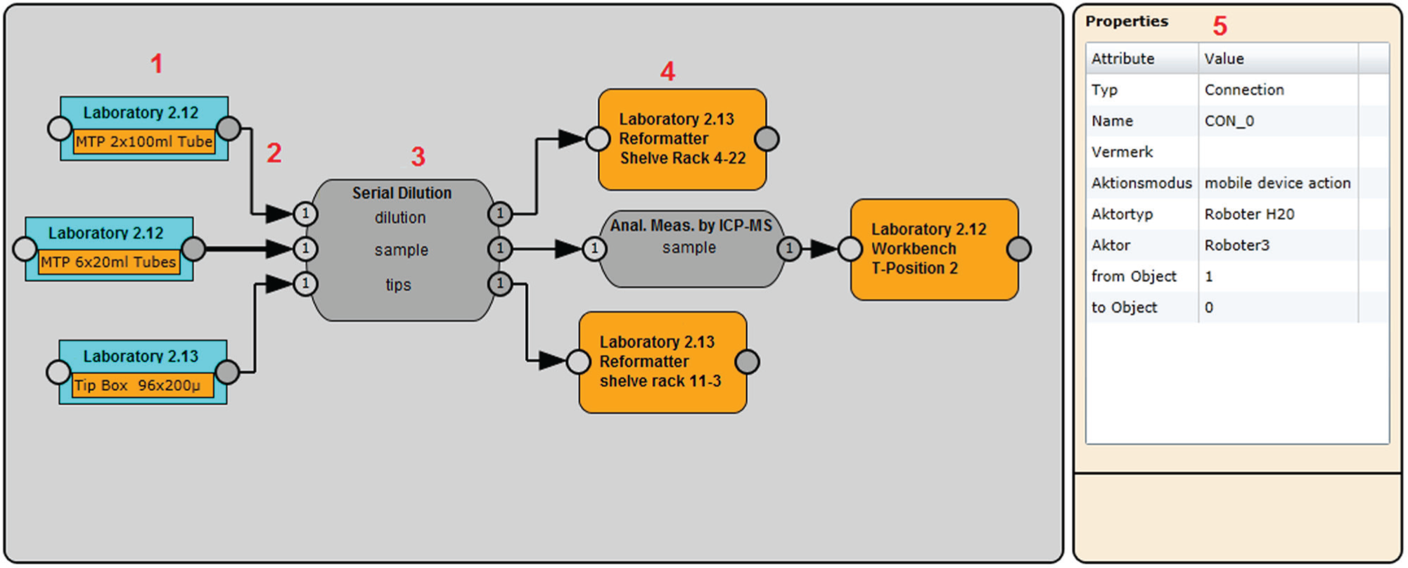
Material flow diagram of the LES for the example application.
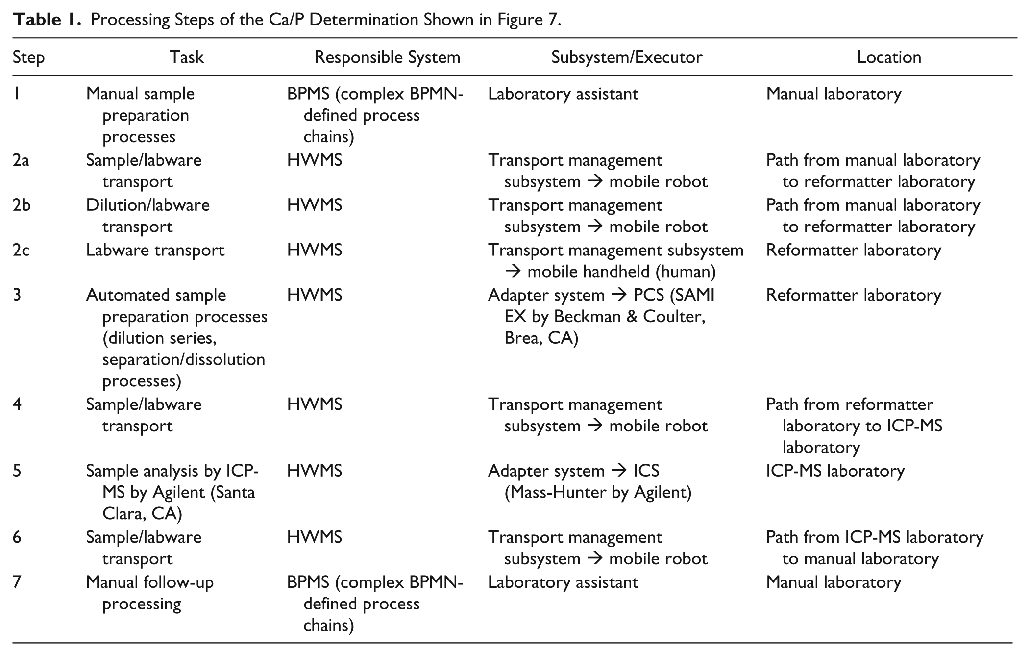
Figure 7 shows the distribution of the automation islands and manual workplaces in celisca, as well as the single steps of the process chain, further explained in Table 1 . Except for process step 2, the application process is handled sequentially. In process step 2, the transport of the samples and the diluting solution from the manual laboratory, as well as the provision of disposable tips for the dilution series, is a condition for the start of process step 3. The transportations to the end position in Figure 6 that are shown after the subprocess “Serial Dilution” are not displayed in Figure 7 , as the labware stays in the shelve rack of the reformatter.
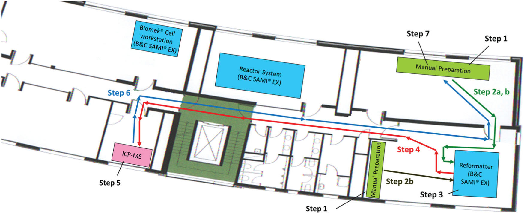
Distribution of the Ca/P determination workflow in the ground plan of celisca.
Processing Steps of the Ca/P Determination Shown in Figure 7.
Discussion
The contribution takes up the exploratory work and application experience of preliminary work17–21 for the introduction of BPM in laboratory automation. In the preliminary work, a comparative direct and non-time-critical coupling of BPMSs with automation components of the process and instrument control level was considered. Thereby low-complexity workflows (simple pre- and post-subprocesses combined with up to three automation islands and appropriately controlled transportation steps; low global process status monitoring of automation islands) were controlled by a BPMS. The extent of the BPMN models, as well as the number of BPMS–automation interfaces, increases very quickly for laboratory automation applications with higher complexity. To handle these situations, the presented LES solution, HWMS, responds especially to the following challenges and purposes:
By using a generic LES, BPMSs can be effectively decoupled from the established structured laboratory automation. In the developed HWMS, material flow-oriented subprocesses can be modeled as a joint process and executed largely independently from the BPMS. In this context, the LES independently covers the transportation tasks between the process executions of the automation islands. For this, the development of a PCS for the use of mobile transportation robots was required, which solves the manual and automated material transport by its own resources and state management. It is recommended that the generic LES offers the BPMS a service-oriented interface with a few comparable state and other process variables for connected subsystems on the process control layer. Time-critical and detailed state-guided process monitoring and material flow control, which are outside the scope of the BPMS definitions, are covered already by the LES. The use of the presented LES approach simplifies the BPMS solution with the integration of more complex subprocesses and can be executed free of conflicts concerning the competing process flows of the BPMS. Concerning flexible laboratory automation, the LES approach offers the advantage of upstream systems integration in a more specified subsystem. Moreover, due to its scheduling functionality, the LES enables parallel execution of similar and different LES models, which use the same lower-layer automation resources (e.g., PCSs and ICSs). Consequently, these LES models can be arbitrarily implemented in loops or in different workflows in the BPMS. A first test of modeling and executing a workflow separated into BPMSs and HWMSs confirms the synergy potential of the activity-oriented BPMN 2.0 and the laboratory automation–specified material flow process notation. This combination improves the process observation of complex laboratory processes using several automation islands and transport logistic solutions.
The approach of a generic LES for the BPM-driven end-to-end workflow automation does not restrict the openness of BPMSs. Furthermore, direct control access of the BPMSs to the subordinated levels of the structured laboratory automation is especially given by consideration of supervised resource availability. The presented LES offers professional users and system engineers a comfortable way to solve complex tasks of systems integration for high-level LSA. An initial example application confirms the general feasibility and effects of LES-BPMS couplings. Further research work will focus on the BPMS-oriented extension of the HWMS approach concerning the optimized interaction between distributed workflow controls of the laboratory automation.
Further activities in this field will focus on the aggregation of BPMS and LES and offer the possibility to consider and compare diverse life science applications between the BPMS-controlled and the BPMS-LES-controlled approach. Investigations on the simplification of the process planning and the reduction of the systems integrations effort for the BPMS-LES approach will follow. Moreover, the cascading of process models over several automation levels will be considered in more detail.
Footnotes
Acknowledgements
The authors thank PD Dr.-Ing. habil. The authors also thank Heidi Fleischer for her support concerning the analytical application and Dr.-Ing. Hui Liu for his expert advice in the field of mobile robotics.
Declaration of Conflicting Interests
The authors declared no potential conflicts of interest with respect to the research, authorship, and/or publication of this article.
Funding
The research project (FKZ: 03Z1KN11), which includes the content of this paper, was financially supported by the Federal Ministry of Education and Research (BMBF, Germany).