
Abstract
Life science areas require specific sample pretreatment to increase the concentration of the analytes and/or to convert the analytes into an appropriate form for the detection and separation systems. Various workstations are commercially available, allowing for automated biological sample pretreatment. Nevertheless, due to the required temperature, pressure, and volume conditions in typical element and structure-specific measurements, automated platforms are not suitable for analytical processes. Thus, the purpose of the presented investigation was the design, realization, and evaluation of an automated system ensuring high-precision sample preparation for a variety of analytical measurements. The developed system has to enable system adaption and high performance flexibility. Furthermore, the system has to be capable of dealing with the wide range of required vessels simultaneously, allowing for less cost and time-consuming process steps. However, the system’s functionality has been confirmed in various validation sequences. Using element-specific measurements, the automated system was up to 25% more precise compared to the manual procedure and as precise as the manual procedure using structure-specific measurements.
Keywords
Introduction
Allowing for applied and basic research applications, life science areas require specific sample pretreatment steps, such as stirring or shaking, aliquoting, diluting, protein precipitation, and sample extraction techniques. However, these sample preparation techniques are the rate-limiting steps in many testing processes. 1 Thus, automating these process steps ensures improved sample throughput and better economical results. 2 Moreover, automated sample preparation will reduce the amount of repetitive and tedious tasks for the operators 3 and will ensure the safety of the analyst 4 by assigning risk-involving procedures, such as handling of highly active substances 5 or potentially infectious biomaterial. 6 Moreover, due to the operator-unattended sample pretreatment, 7 automated systems eliminate the training time for the analyst and personal errors in sample preparation. 8 Therefore, these systems reduce the variability in sample preparation, 9 improve the accuracy of the experiments, and allow for rapid analysis.
Commercially available automated workstations are usually configured for handling the standardized multititer plate (MTP) format. Accomplishing DNA and RNA assays and in addition the analysis of (therapeutic) proteins, 10 biological applications use especially this format and represent, therefore, the prime candidates for laboratory automation. 11 Moreover, using this format, automated biological sample preparation contributes to an increased throughput 12 and enables simultaneous screening of many excipients and experimental conditions, such as storage temperatures, mechanical stresses, buffers, salts, and surfactants. 13
Nevertheless, commercially available automated systems are not suitable for common analytical sample preparation processes. Allowing for the analysis of small molecules and mixtures of molecules, analytical requirements differ significantly from biological applications. In detail, because environmental and industrial solid samples usually provide nonhomogeneous consistency, analytical sample preparation calls for higher volume ranges (up to liters), 14 allowing for dissolving higher quantities of the solid samples. The utilization of highly active aqueous solutions (such as concentrated acids 15 ) or (toxic) organic solvents with different viscosities has to be considered requiring the utilization of inert materials.
Demanding lower volume ranges, 16 biological sample preparation and measurement processes simply involve the analysis of food 17 and body fluids, 18 expression of cell metabolism products, 19 application of biomolecules, 20 culture media, 21 and washing solutions. 22 Accordingly, all of these biological tasks provide just nonhazardous pH values and call for standard laboratory conditions ensuring the utilization of the MTPs. 23 In contrast, performing high-volume, nonstandard temperature and pressure procedures, 15 the use of specialized vessels has remained indispensable for multistep analytical sample pretreatment.
Furthermore, analytical process steps call for various workstations, ensuring different tasks and functions. Because existing systems handle only a few steps of a complex analysis scheme 24 or offer a fixed solution for a single application, upgradable automation processes and flexible analytical sample pretreatment are still an unsolved issue.
Consequently, the most important challenge and, therefore, the purpose of this investigation was the design, realization, and evaluation of a suitable system performing automated sample pretreatment and high-performance flexibility. Hence, facilitating analytical sample pretreatment, the designed system has to be capable of dealing with the wide range of required vessels, simultaneously ensuring less cost and time-consuming process steps.
Materials and Methods
General Conspectus
System integrators are capable of moving labware, such as MTPs or individual vials and tubes, throughout the integrated system. Thus, allowing for system integration, common laboratory robots, such as the ORCA (Beckman Coulter, Brea, CA), the Motoman HP3JC (Yaskawa, Kitakyūshū, Japan), or the BenchBot Robot (Agilent, Santa Clara, CA) are commercially available.
The central elements of the presented system (as shown in Figs. 1 and 2 ) are, however, two ORCA robots (1) acting as system integrators and transportation systems. Facilitating easy access to a broad range of peripheral devices and instruments, the ORCAs were mounted on two orthogonal 2-m rails. Moreover, effectively doubling the useable workspace, the extended envelope feature enables the robot arms to operate on both sides of the rail, respectively. In addition, the designed regrip station (2) allows for the labware exchange between both ORCA robots.
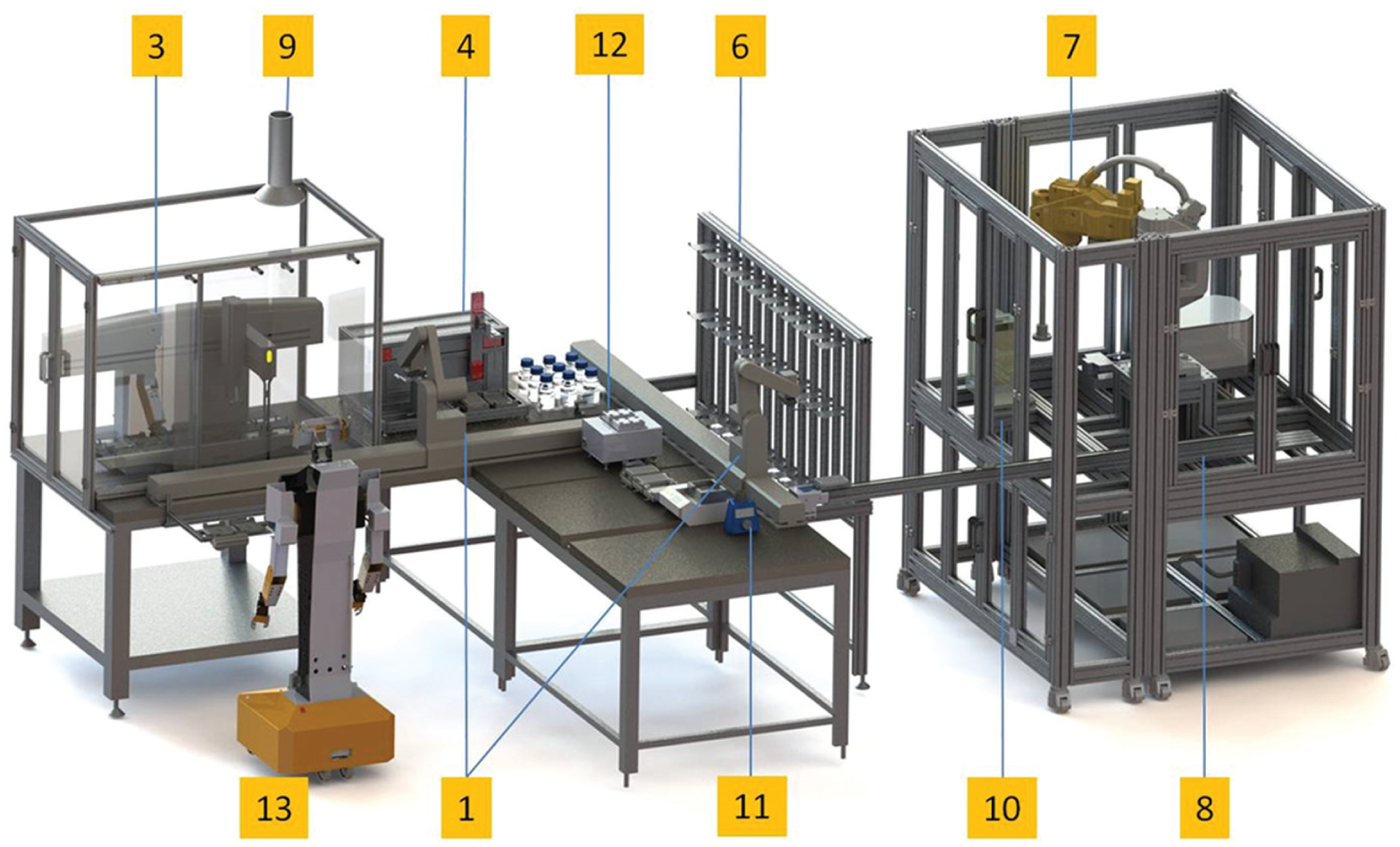
Computer-aided design of the automated system: (1) two ORCA robots (Beckman Coulter, Brea, CA); (2) designed regrip station, not shown; (3) Biomek 2000 (Beckman Coulter); (4) diluting station; (5) Digitus HQ webcam (ASSMANN, Luedenscheid, Germany), not shown; (6) flexible sample hotel; (7) SCARA robot Stäubli TS60 with housing (Stäubli, Bayreuth, Germany); (8) shuttle; (9) housing of the Biomek 2000, including an exhausting system; (10) analytical balance BP211 (Sartorius, Goettingen, Germany); (11) ionizer ANTISTAT 2000 (CEM, Kamp-Lintfort, Germany); (12) MHL 23 heating and shaking device (HLC BioTech, Bovenden, Germany); and (13) mobile robot H20 (Dr. Robot Inc., Markham, Canada).
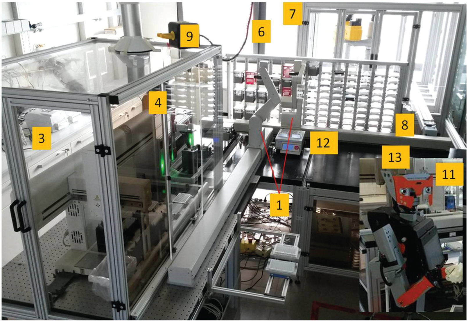
Actual picture of the automated system: (1) two ORCA robots (Beckman Coulter, Brea, CA); (2) designed regrip station, not shown; (3) Biomek 2000 (Beckman Coulter); (4) diluting station; (5) Digitus HQ webcam (ASSMANN, Luedenscheid, Germany), not shown; (6) flexible sample hotel; (7) SCARA robot Stäubli TS60 with housing (Stäubli, Bayreuth, Germany); (8) shuttle; (9) housing of the Biomek 2000, including an exhausting system; (10) analytical balance BP211 (Sartorius, Goettingen, Germany), not shown; (11) ionizer ANTISTAT 2000 (CEM, Kamp-Lintfort, Germany), showing detail; (12) MHL 23 heating and shaking device (HLC BioTech, Bovenden, Germany); and (13) mobile robot H20 (Dr. Robot Inc., Markham, Canada), in front of the Biomek 2000, showing detail.
Liquid delivery and dilution steps have been performed using the integrated Biomek 2000 (Beckman Coulter) (3), which accomplishes pipetting steps up to 1 mL. Higher volume ranges can be delivered using an in-house designed diluting station with a Hamilton dispenser (Hamilton Bonaduz AG, Bonaduz, Switzerland) (4), including an incorporated 10-mL gastight syringe. In addition, the Digitus HQ Webcam USB 2.0 (ASSMANN, Luedenscheid, Germany) (5) has been implemented into the automated system, ensuring sample identification, while using 2D barcode processing and reading. Furthermore, samples are stored in the flexible sample hotel (6), which provides 196 shelves varying in height and allowing for storage of different kinds of MTPs—until they are processed within the system.
Moreover, the SCARA robot (TS60; Stäubli, Bayreuth, Germany) (7) assembly, including a crimping die, which is part of the Crimp Capping Station (Zymark Corporation Model Z-420; Zymark, Hopkinton, MA), offers the availability of individual capping. Furthermore, the 2-m solid shuttle transport system (8) has been integrated, supplying transport to the SCARA robot assembly. Due to safety reasons, the developed system has been partially covered with a housing, which can be exhausted (9).
The weighing station (analytical balance BP211D; Sartorius, Goettingen, Germany) (10) allows for accurate weighing processes. Moreover, the weighing station is loaded using the high-precision SCARA robot, supplying individual weighing of the required vials. Moreover, the ionizer ANTISTAT 2000 (CEM, Kamp-Lintfort, Germany) (11) avoids electrostatic charge of the samples, allowing for fast and precise weighing steps. The heating and shaking device MHL 23 (HLC BioTech, Bovenden, Germany) (12) has been integrated, allowing for derivatization and homogenization of the samples. Moreover, the designed Positive Pressure Unit can be simply assembled on the Biomek liquid handler, providing positive-pressure solid phase extraction (SPE) applications. In addition, automated analytical sample preparation includes microwave digestion steps. However, due to safety reasons, these steps have to be performed under a separated hood.
Analytical devices can be integrated into the developed SamplePrep station. Supplying flexible and precise sample transport between the automated sample preparation system and further external stations, such as the detection and separation systems, a mobile robot system (13) has been developed. Finally, a specific integration module has been developed for every custom-integrated device using the SILAS software developer kit.
Concept of Standardized Labware Design
Commercially available automated workstations are usually configured for handling the standardized MTP format. Due to the higher volume ranges and the specific conditions required for performing analytical procedures, reaction chambers of this labware format are not sufficient to fulfill multistep analytical sample pretreatment. Therefore, the use of specialized vessels has remained indispensable. In detail, even for one specific application, several labware types are required, such as the analysis and calibration vessels, special treatment vessels, and, moreover, several reservoirs for organic and inorganic solvents.
Nevertheless, embedding these vessels into the standardized MTP footprint represents a suitable solution, allowing for system adaption and, therefore, ensuring the availability of existing workstations for multistep analytical sample pretreatment. The embedded vessels, however, have to meet the specifications of the controller software to provide the entire task performance of the adapted workstations. The predetermined labware parameters are based on the MTP contours, including a maximum length of 130 mm and a maximum width of 120 mm. Nevertheless, by way of derogation from the standard MTP contours, the liquid handler controller software (Bioworks, Beckman Coulter, Brea, CA) allows for a maximum height of 115 mm. Consequently, due to this deviation, embedding the applicable vessels into the standardized MTP footprint (as shown in Fig. 3 ) enables the adaption of existing workstations for multistep analytical processes. In addition, this concept idea allows for simultaneous handling of up to 24 vessels, supplying less cost and time-consuming process steps. Moreover, representing a flexible solution, embedding is applicable for a wide range of vessels.
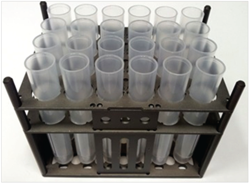
Image of a designed, multititer plate–formatted labware type with 24 embedded calibration vessel. Embedding the analytical vessels into the standardized MTP footprint represents a suitable solution, ensuring the availability of existing workstations for multistep analytical sample pretreatment. The concept idea of embedding is applicable for a wide range of vessels and facilitates, therefore, the performance of different kinds of analytical applications.
System Integrator
Working as system integrators, two classical laboratory robots (ORCA) were implemented into the automated system, providing six axes of movement. With high degrees of freedoms and four revolute joints, these articulated robots provide high flexibility and move with dexterity while manipulating various labware, such as MTPs, vials, and tubes. 25 The additional regrip station enables labware exchange between both robot arms.
Based on the standardized MTP footprint, the ORCA robots, or any other common laboratory robot that is capable of handling the MTP format, are able to deal with the designed labware types. Due to the standardized footprint, the ORCA robots are able to place every kind of designed labware type on any existing labware position throughout the integrated system. Therefore, embedding allows for various kinds of applications without any changing of labware positions.
Liquid Handling
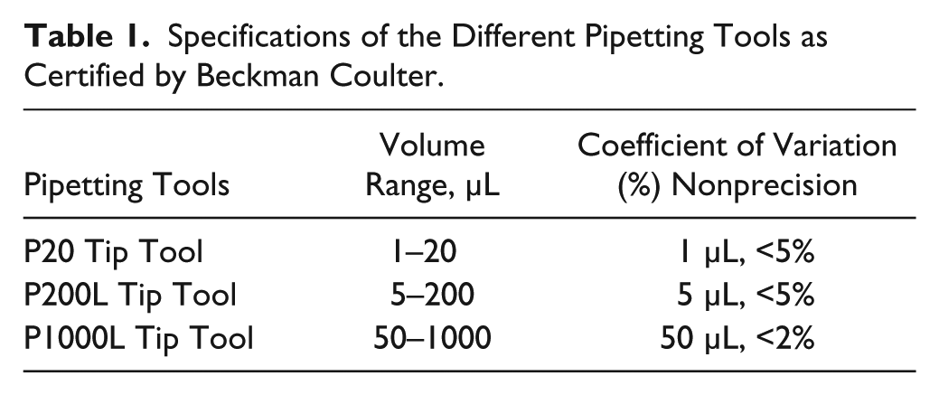
The Biomek 2000 has been implemented performing liquid handling in the range of 1 to 1000 µL while using the designed labware types. Pipetting precision, however, depends on the required volume and the chosen pipetting tool, which is depicted in Table 1 using the coefficient of variation (CV).
Specifications of the Different Pipetting Tools as Certified by Beckman Coulter.
Pipetting tips for the Biomek 2000 require an additional barrier to avoid contaminations of the Biomek 2000 pipetting tools, which can occur while using evaporating fluids, such as dichloromethane or vapor-generating acids. In addition, the Biomek system has been covered with a housing that can be exhausted. For constructing the housing, acrylic glass panes and aluminum profiles have been used supplying the following dimensions: 1310 mm × 835 mm × 966 mm. The Biomek housing is designed as a removable hood. At the front side and at the lateral side, there are two doors providing fast and easy operator access. The front door can be opened by the ORCA robot using a twin track guide with rollers. On the top side, the housing is connected with the exhausting system, which is capable of aspirating up to 37 cubic decimeters of air per second. The aspirating rate can be adjusted manually.
For handling higher volume ranges, a further liquid handler has been designed. The liquid handler is equipped with a Cartesian robotic configuration and two additional labware holders requiring the MTP footprint. Using the Hamilton dispenser (Microlab 511C) with an incorporated 10-mL gastight syringe, inaccuracy (CV) of liquid handling is lower than 1%. Providing volumes up to 10 mL, the Microlab gastight syringe consists of borosilicate glass, a polytetrafluoroethylene (PTFE) Luer Lock termination, and a PTFE tipped plunger. Supplying inert materials, Teflon fluorinated ethylene propylene (FEP) tubing creates the fluid path connecting one reservoir with the Hamilton dispenser and the Hamilton dispenser with the Cartesian robotic configuration.
Therefore, the designed liquid handler is capable of performing high-precision dispensing, simplifying the liquid handling steps. Moreover, using the presented, standardized labware design, both liquid handlers are capable of handling several vessels simultaneously.
Sample Handling
Barcode Reading and Sample Storage
Because a large percentage of laboratory errors are related to errors in sample identification, 26 data audit trails have become an important part of manufacturing quality systems documentation. 27 Thus, supplying 2D barcode reading, the Digitus HQ Webcam USB 2.0 has been implemented into the automated system. Moreover, barcode processing and reading are necessary due to the high number of samples that have to be analyzed.
Moreover, sample storage options have been offered by the automated system using a flexible sample hotel. The sample hotel provides 196 shelves and has been constructed using diverse aluminum profiles, which require labware loading by the central ORCA robots. Calling for the MTP footprint, the shelves allow for the storage of the conceived trays.
(De)Capping and MTP Handling
For automating the sealing process, the most important impetus was the fact that the manual sealing puts physical stress on the human hands that may contribute to occupational injuries, such as tendonitis and carpal tunnel syndrome. Furthermore, this task is potentially hazardous as it may expose the scientist to the samples via accidental spillage or breakage. 2
Sealing in analytical sample preparation comprises crimping, capping, and screwing. However, crimping and screwing the vessels is an underestimated challenge, respectively, because the vessels have to be transferred to a crimp/screw-tightening robot one by one. Moreover, allowing for tight sealing, screwing calls for force measurement and straight alignment of the screw caps.
Thus, the developed concept comprises the idea of capping the whole MTP footprint, including all the implemented vessels, with just one lid. Allowing for simultaneous capping of up to 24 vessels, the Biomek gripper tool is capable of gripping this lid in one single step. Because the designed labware types and, moreover, the conceived lids meet the specifications of the liquid handler software (Bioworks), the gripper tool supplies automated (de)capping as certified by the manufacturer for all automatic moves. Thus, the Biomek 2000 accomplishes (de)capping without any fail (n = 100). Allowing for gripping the whole tray, a gripper lip is necessary. A second lip has been attached, providing the tight fit of the vessels.
Crimping and Individual Sample Handling
To ensure concentration stability while handling volatile components, individual capping, including a very tight seal, is still required. Consequently, crimp caps with septa have been chosen. Crimping requires individual sample handling because the caps and vessels have to be transferred to a crimp-tightening robot one by one, which is enabled using the Stäubli TS60 SCARA robot. This robot provides high-speed and high-precision sample handling. Using a pneumatic system, including a suitable end-effector (SMC, Tokyo, Japan), and also the developed, flexible finger design, the TS60 robot is capable of gripping and placing individual vials and caps.
The crimping construction comprises two additional linear pistons (SMC), providing x- and z-axis of movement. Moreover, the TS60 SCARA robot assembly includes a crimping die (part of the Zymark Crimp Capping Station), which is mounted on special aluminum profiles. The pistons, the crimping die, and the TS60 are connected via a pneumatic system (SMC), which is also used to control the end-effector.
Using the end-effector with the flexible finger design, the TS60 is capable of gripping the vials and crimp caps. Thus, the TS60 puts one crimp vial and one crimp cap into the crimping adapter. Subsequently, performing x- and z-axis of movements, the pneumatically controlled pistons provide the final crimping position of the crimping adapter. Crimping is pneumatically accomplished using the crimping die. Finally, the pistons back up to their initial position, and the TS60 robot puts the crimped vials back into the conceived trays using its flexible finger design. Due to the high repeatability (±0.01 mm) of the TS60 SCARA robot, gripping and placing is accomplished without any fail. Crimping is also accomplished without any fail (n = 100) because the success of crimping depends on the right positions of the caps placed by the SCARA robot.
Due to the increased space requirements of the SCARA robot and its performance vibrations during rotation, the TS60 calls for a separated workbench. This workbench has to be integrated using a solid shuttle system. Supplying 2-m linear guidance while using an engine-driven toothed belt, the designed shuttle system has been constructed. Using aluminum profiles and the MTP-formatted labware holder, the shuttle system requires labware loading by the central ORCA robots. Due to the high-speed robot motions and its operating distance, the SCARA robot assembly has been covered with a housing. Aluminum profiles have been used for constructing the housing. At the front side and at the lateral sides, there are two doors, respectively, providing fast and easy operator access for service, cleaning, and placing labware. The dimensions of the housing are as follows: 1600 mm × 1441 mm × 1085 mm.
Sample Treatment and Analytical Devices
The implemented weighing station BP 211D provides an internal calibration weight, enabling accurate weighing processes. The station offers dual range weighing with 0.01 mg sensitivity to 80 g and of 0.1 mg sensitivity to 210 g. The weighing station is loaded using the high-precision SCARA robot, allowing for individual vial treatment. Avoiding the electrostatic charge of the samples and, therefore, the introduction of contamination particles, the ionizer ANTISTAT 2000 supplies easy and precise weighing steps. Using Excel files, data storage and sample dosage options have been provided.
Accomplishing derivatization reactions to convert the analyte molecules into an appropriate form for the detection or separation systems, the heating and shaking device MHL 23 attains temperatures up to 130 °C. Moreover, the shaking options enable the homogenization of the treated sample solutions, allowing for completed reaction processes. The designed exchangeable thermo-block adapters (as shown in Fig. 4 ) can be used for any kind of application using 2-mL crimp, snap, or screw-cap vials. The vials, however, have to be embedded into the conceived trays using the MTP-formatted labware design that matches with the thermo-block adapters and enables, therefore, precise stacking steps. Providing connective heat transfer, the chosen material of the thermo-block adapters and the conceived trays is aluminum.
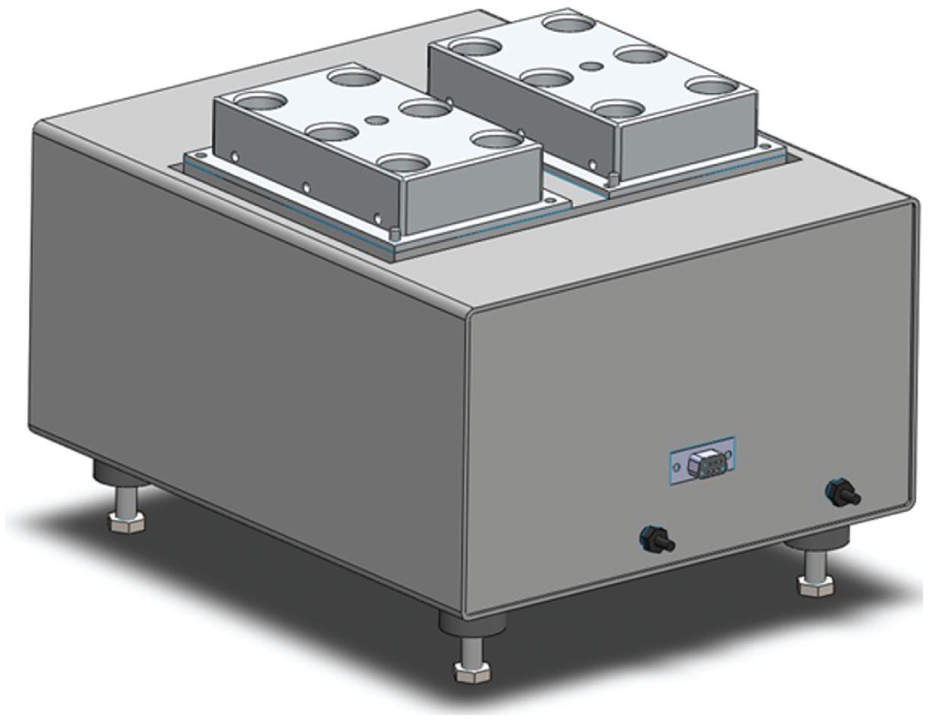
A 3D computer-aided design of the heating and shaking device MHL 23, including two exchangeable thermo-block adapters. The heating and shaking device allows for derivatization reactions and homogenization of the sample solutions. The aluminum-based thermo-block adapter matches with the conceived, multititer plate–formatted labware design, enabling precise stacking steps and connective heat transfer.
Providing positive-pressure SPE applications, the developed unit 28 can be simply assembled on the Biomek workspace. Using the pipetting options of the Span-8 pipetting tool and the stacking options of the Biomek gripper tool enables automated loading and handling of the columns. Moreover, using the designed fritting-based pressure flow reduction technology, the Positive Pressure Unit avoids vacuum manifold–specific difficulties, allowing for reproducible recovery rates. To provide extensive sample preparation techniques, an ultrasonic bath (Bandelin Sonorex, Berlin, Germany) has been implemented, allowing for dissolving and fragmenting the required substances.
Moreover, automated analytical sample preparation includes microwave digestion steps. Due to safety reasons, these steps have to be performed under a separated hood. However, performing microwave digestion is simple and fast using the applied Xpress vessels (CEM). In detail, process steps comprise sample dosage that is provided by the automated system, insertion of the vessels, and starting of the microwave digestion program. After sample treatment, the converted analyte molecules have to be analyzed using the analytical devices, such as inductively coupled plasma mass spectrometry (ICP-MS) and gas chromatography/mass spectrometry (GC/MS).
Software Integration
For integrating third-party equipment, devices or the device control software have to be interfaced with the upper level of control software, called integration software. Hence, translating data and commands from the upper control instances to the devices or devices’ software and vice versa, drivers have been written.
Regarding the represented automated system, the standardized SILAS protocol is used that supports custom integration into the automated system, which is controlled by the SAMI Workstation Ex software (Beckman Coulter). SILAS is an integral content of the SAMI Workstation Ex software and based on Microsoft (Redmond, WA) ActiveX messaging. However, integration of devices running under other platforms is feasible using network communication. Hence, any device that is controllable via electronic interfaces, such as RS232, USB, Firewire, or Ethernet, can be integrated. Moreover, any device that is controlled by its own software can be integrated if the device software has a remote control interface, such as COM, ActiveX, OLE, DDE, or TCP/IP communication. Thus, the designed dilution station, the heater and shaker device MHL 23, the scale BP 211D, the barcode reader, and the designed shuttle system have been integrated into the automated system using direct integration via hardware interfaces, such as RS232 and USB. Besides, device software integration has been required for the ORCA, the Stäubli TS60, and the Biomek 2000. These automation devices communicate with their own proprietary host controller software. Running on the same automation controller, their device integration modules communicate with the host controller software. Furthermore, device software integration has been required for mobile robot transport, exerting its own automation controller. Using hardware interfaces, the device integration module communicates with the device software.
Communicating with the SILAS router and with the device/device controller software, a specific executable module has been developed for every custom-integrated device. The SILAS software developer kit contains a prebuilt module framework facilitating custom integrations. Communication on the SILAS level is message based and controlled by the SILAS router. Providing direct settings of the operation parameters for more simple devices or a selection of predefined methods for more complex devices, such as liquid handlers, every device needs a user interface to parameterize the functions of the device. Thus, for using more complex applications, additional hardware platform-independent method editing, scheduling, and runtime control software is required, providing a time-efficient run and, therefore, cost-effective system usage. Powered by SAMI Workstation EX software, which is used for all automation processes of the presented system, the software allows for developing (via SAMI Editor), scheduling (via SAMI Scheduler), monitoring, and running (via SAMI Run Time) multiple processes on the integrated systems.
Integration with External Stations (Mobile Robot Transport)
Providing flexible and precise sample transport between the automated sample preparation system, the microwave hood, and other external stations, such as the detection and separation systems, a mobile robot system has been integrated. The mobile robot system comprises several H20 robots. These robots are designed and built on the i90 robot base featuring a 12-inch touchscreen tablet, two large arms (Hawk arms), dual-camera animated head (Hawk head), indoor GPS navigation system, and auto-docking/recharging station.
The mobile robot transport has been provided by the Hierarchical Workflow Management System (HWMS) using the Transportation and Assistance Control System. This system controls not only the robots’ but also the humans’ resources for transportation tasks while getting queried for transportation orders. Moreover, monitoring the process environment, the Transportation and Assistance Control System allows for periodic and maintenance tasks that have to be performed on the automation islands. With respect to the HWMS’s preselection, all of the transportation orders are locally queued and distributed among the available transporters. Dealing with their specific requirements, the Transportation and Assistance Control System provides different communication interfaces.
Moreover, fulfilling the particular tasks, the HWMS facilitates not only labware and substances exchange but also data exchange (as shown in Fig. 5 ) between the automation islands, such as the automated sample preparation system, hoods, and analytical devices. Allowing for remote control of the automation islands, the Adaptive Workstation Control System connects different third-party device software, such as SAMI EX and MassHunter (Agilent), to the HWMS. Executing analytical measurement processes, reporting the results, and supplying status updates, the Adaptive Workstation Control System queries the analytical operations while using SAMI Schedule and Run options. Consequently, the HWMS provides a complete software structure that allows for the automation of analytical processes while using the integration of external stations, remote control of the automation islands, and postsample preparation steps, including sample analysis and evaluation processes.
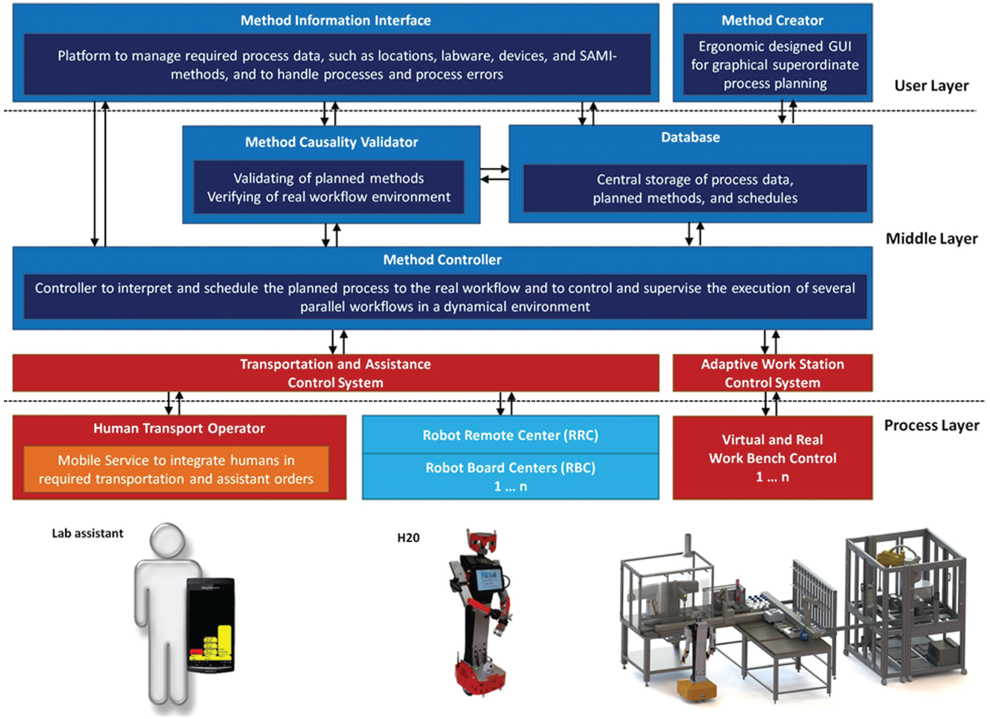
Flowchart of the Hierarchical Workflow Management System (HWMS). The mobile robot transport has been provided by the HWMS. However, this system controls not only the robots’ but also the humans’ resources for transportation tasks. Moreover, the HWMS enables not only labware and substances exchange but also data exchange between the numerous automation islands, such as the automated sample preparation system, hoods, and analytical devices.
Results and Discussion
Ensuring element- and structure-specific measurements, various validation sequences have been performed (as shown in Fig. 6 ). Accomplishing both automated and manual sample pretreatment, results have been measured using specific separation and detection systems, such as ICP-MS and GC/MS. Finally, the results have been evaluated and compared with each other.29,30 For validating the automated and the manual sample preparation processes, bias error of the measuring instrument (according to DIN 1319), repeatability standard deviation (SD) (according to DIN 1319), reproducibility SD (according to DIN 1319), and discrimination threshold (according to DIN 1319, also called limit of detection according to DIN 32645) have been calculated.
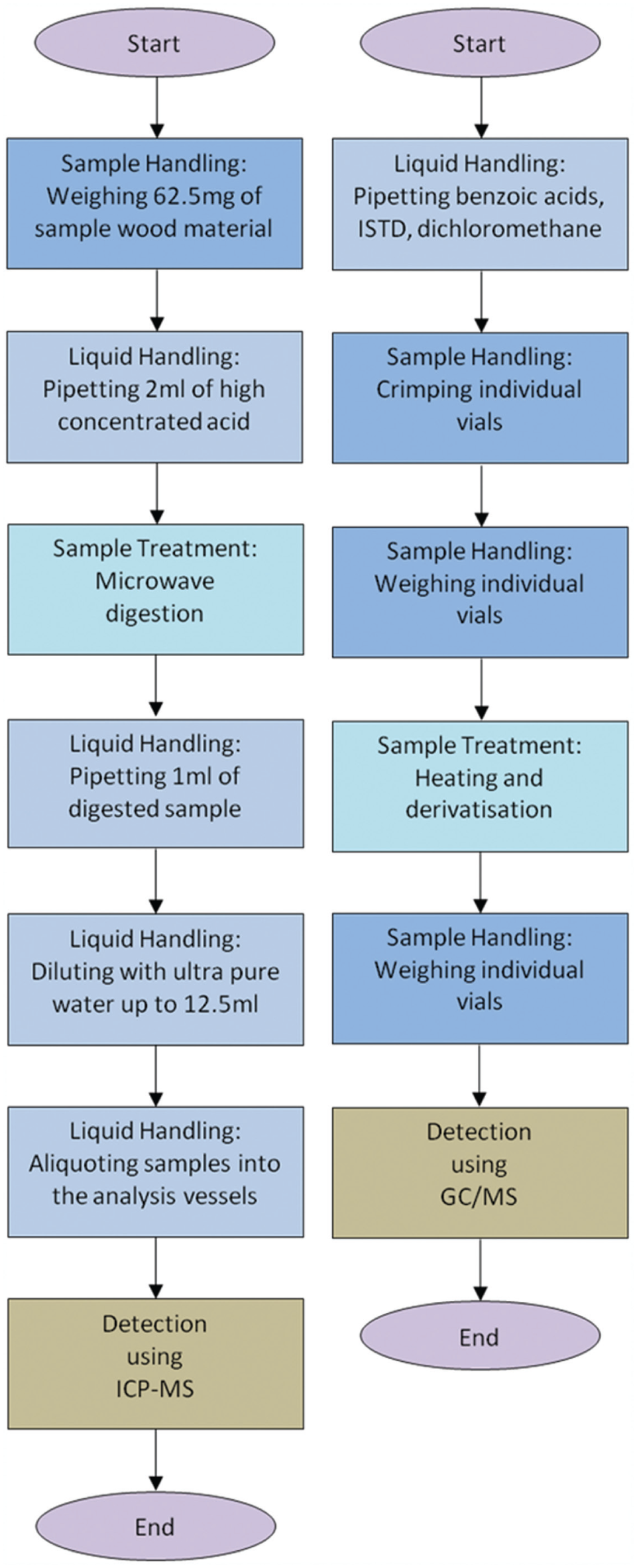
Required sample pretreatment steps for the element-specific (left side) and the structure-specific (right side) validation sequence. The element-specific measurement comprises the following: (1) weighing of referenced wood material (using the TS 60 assembly for the automated process), (2) pipetting of high concentrated acid (using the described liquid handlers for the automated process), (3) microwave digestion (using the mobile robot transport for the automated process), (4–6) various pipetting steps (using the described liquid handlers for the automated process), and (7) detection using inductively coupled plasma mass spectrometry (ICP-MS). The structure-specific measurement comprises the following: (1) pipetting (using the described liquid handlers for the automated process), (2) individual vial crimping (using the TS 60 assembly for the automated process), (3) individual vial weighing (using the TS 60 assembly and the implemented balance station for the automated process), (4) sample treatment (using the implemented heater/shaker device and the developed multititer plate–formatted labware adapter for the automated process), (5) individual vial weighing (using the TS 60 assembly and the implemented balance station for the automated process), and (6) detection using gas chromatography/mass spectrometry (GC/MS). ISTD, internal standard (cis-decahydronaphthalene).
Element-Specific Measurements
Element-specific measurements have been performed, providing experimental applications and, therefore, a validation sequence. The sample preparation sequence includes a mercury analysis and is shown in Figure 6 . The sample pretreatment for both the automated and the manual processing comprises various weighing and dilution steps, as well as microwave digestion steps. Nevertheless, using ICP-MS analysis, the measurement process has been the rate-limiting step (3 min/sample). However, because the automated system allows for 24/7 investigations, the automated sample pretreatment enables the investigation of up to 480 samples per day.
Bias error (%) of the measuring instrument (ICP-MS) was 1.2% and was calculated by measuring 10 times a sample that was processed using the automated system. Measuring 10 times a sample that was processed using the manual sample preparation procedure, bias error (%) of the measuring instrument was 1.6%. Discrimination threshold/limit of detection was calculated from the mean value of 10 blank measurements and 3-fold of the value’s SD. Discrimination threshold/limit of detection was 8.4 ng/L using a blank solution that was processed by the automated system and 6.1 ng/L using the manual processing.
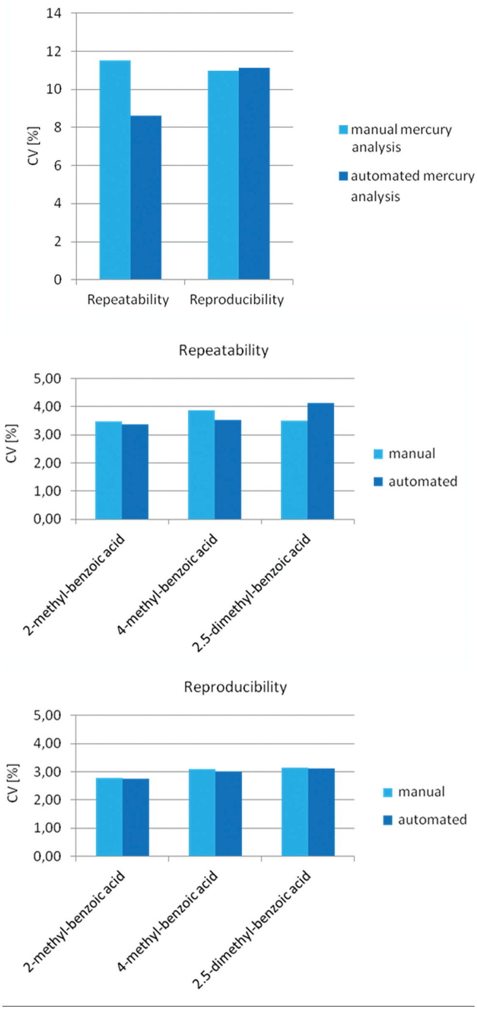
Validation results are shown in Figure 7 , allowing for the comparison of the manual processing and the automated sample preparation system. Using repeatability conditions for the automated and the manual sample preparation process, 25 samples per day have been prepared. The applied sample masses and thus homogeneity of the samples were the same. Due to the very low final concentration of mercury, which was 1.5 µg/L in the analysis solution and 0.6 mg/kg in the solid matter, the maximum SD (%) is allowed to be 11.52%, according to the Horwitz definition. Performing ICP-MS measurements, calculated repeatability SD (%) of the automated process was 8.6%. Repeatability SD (%) of the manual processing was 11.5%. Hence, compared with the manual procedure, the automated process was up to 25% more precise.
(
Preparing 10 samples per day on 5 consecutive days, reproducibility SD was calculated using reproducibility conditions. Using the ICP-MS measurement results, reproducibility SD (%) of the automated process (11.13%) was similar to the reproducibility SD (%) of the manual processing (10.98%). Results did not exceed the maximum value (SD [%] = 11.52%) according to the Horwitz definition. Moreover, verified by the David test, all measured values followed a normal distribution.
Structure-Specific Measurements
Structure-specific measurements have been performed for the detection of benzoic acids. Thus, the automated system and the manual processing were compared with each other using derivatization and subsequent GC/MS analysis. Providing fast and easy environmental analysis, the automated process enables 24/7 investigations and is shown in Figure 6 (flowchart presenting the liquid handling and sample treatment steps). However, the rate-limiting step was the derivatization step (2.5 min/sample).
Bias error (%) of the measuring instrument (GC/MS; 10 measurements) was 0.8% for samples processed on the automated system, compared with 1.3% for manual processed samples. Discrimination threshold/limit of detection was calculated from the mean value of 10 blank measurements and 3-fold of the value’s SD. Discrimination threshold/limit of detection was 0.43 mg/L using a blank solution that was processed using the automated system and 0.36 mg/L using the manual processing.
Performing repeatability and reproducibility testing for structure-specific measurements, the automated sample preparation process was as precise as the manual testing. In detail, preparing 24 samples per day, repeatability SD was calculated using repeatability conditions for both the automated and the manual sample pretreatment. Using the GC/MS measurement results, repeatability SD of the automated process was between 3.36% and 4.14% for three different benzoic acids, whereas repeatability SD of the manual procedure was between 3.48% and 3.86% (as shown in Fig. 7 ).
Preparing 10 samples per day on 5 consecutive days, reproducibility SD was calculated using reproducibility conditions. Using the GC/MS measurement results, calculated reproducibility SD of the automated system was between 2.76% and 3.1% for three different benzoic acids (as shown in Fig. 7 ). Reproducibility SD of the manual procedure was between 2.77% and 3.15%. Results did not exceed the maximum value according to the Horwitz definition, which was 6.39%. Moreover, verified by the David test, all measured values followed a normal distribution.
Regarding further investigations, such as the implementation of a filtering device, additional measurements have to be performed extending the provided application spectrum. Finally, all applications will be performed in a high-throughput manner, supplying 24/7 investigations for a wide range of environmental and pharmaceutical samples.
Footnotes
Declaration of Conflicting Interests
The authors declared no potential conflicts of interest with respect to the research, authorship, and/or publication of this article.
Funding
The authors disclosed receipt of the following financial support for the research, authorship, and/or publication of this article: The authors thank the State Ministry of Education and Research (Ministerium für Bildung, Wissenschaft und Kultur MV, Germany) for the financial support of this project (FKZ: V-630-S-105-2010/352 and V-630-F-105-2010/353). The work was further supported by the Federal Ministry of Education and Research (FKZ: 03Z1KN11).