
Abstract
The field of centrifugal microfluidics has experienced tremendous growth during the past 15 years, especially in applications such as lab-on-a-disc (LoD) diagnostics. The strength of LoD systems lies in its potential for development into fully integrated sample-to-answer analysis systems. This review highlights the technologies necessary to develop the next generation of these systems. In addition to outlining valving and other fluid-handling operations, we discuss the recent advances and future outlook in four categories of LoD processes: reagent storage, sample preparation, nucleic acid amplification, and analyte detection strategies.
Introduction
During the past 15 years, centrifugal microfluidics has emerged as an advanced diagnostics platform for point-of-care assays. A centrifugal microfluidic device typically takes the shape of a compact disc (CD) and incorporates interconnecting fluidic channels and chambers that are fabricated into the device. These microfluidic discs are capable of performing complex assays ranging from in vitro diagnostics to water quality analysis. Furthermore, recent developments have evolved CD microfluidics technology to become increasingly portable, low cost, and easy to use, making it an ideal system for applications at the point of care. The recent development of unique approaches to sample preparation, fluid-handling, DNA amplification, and other enabling technologies has allowed for the integration of multiple fluidic and analytical steps, leading to complete micro-total-analysis systems (µTAS) on a CD.
Centrifugal microfluidic devices, also called lab-on-a-disc (LoD) systems, comprise a subcategory of lab-on-a-chip (LoC) devices. The advantages of LoC platforms include reduced cost, the use of smaller amounts of materials and reagents, faster reaction times due to small liquid volumes and diffusion distances, portability, and programmability. Although LoD systems incorporate the same advantages as miniature chip-based systems, their superiority lies in their inherent simplicity. A simple motor generates several pseudo-forces on the platform: the centrifugal force, which acts as a liquid pump and generates a force gradient affecting fluids differently at varying radial positions; the Coriolis force, which allows for direction-specific liquid-pumping control; and the Euler force, which can be used to create turbulence during mixing. The disc rotation facilitates multiplexing of several assays on a single disc, separating components of a sample by density, eliminating trapped bubbles, and allowing liquids to be pumped without direct contact with external hardware (see the expanded list in Table 1 ). A comprehensive comparison of the characteristics of different microfluidic platforms can be found in the dissertation by Jia. 1
Characteristics of the Lab-on-a-Chip (LoC) and Lab-on-a-Disc (LoD) Platforms.
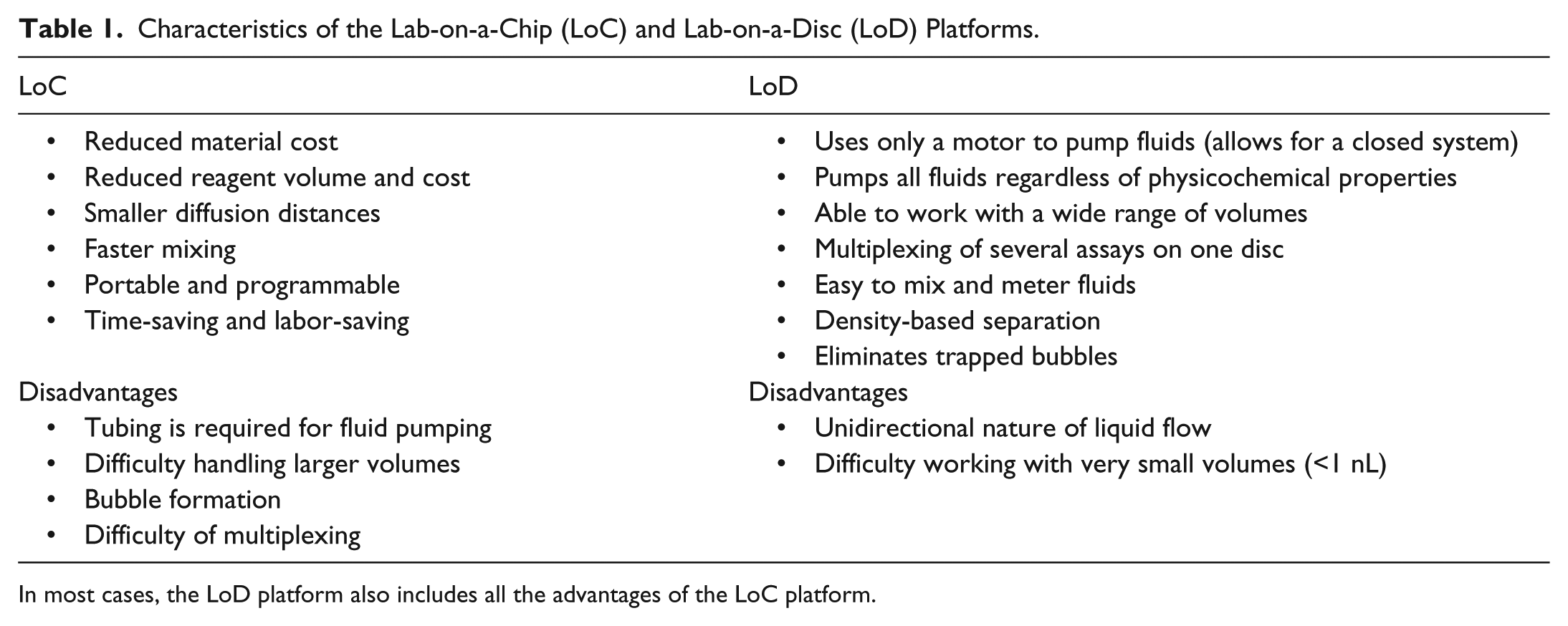
In most cases, the LoD platform also includes all the advantages of the LoC platform.
Although many different assays, such as enzyme-linked immunosorbent assay (ELISA) and blood plasma separation assays, have already been automated on the LoD platform, there is a demand for a wider range of fully integrated assays that require precisely controlled operational parameters. The main focus of this review is on molecular diagnostic assays, which are especially challenging to implement on centrifugal microfluidic platforms and have not been adequately covered in previous reviews.2–6
This article first provides a background of the physics framework of the centrifugal system before introducing the most common fabrication methods used for prototyping and mass production of microfluidic discs. Operations such as valving, pumping, mixing, and volume definition are important for sequencing the different fluidic processes in any on-disc assay. Therefore, a substantial section of this review, the Fluid-Handling Techniques section, is devoted to techniques that perform these tasks on a LoD platform.
Molecular diagnostic assays need to include storage and dispensation of reagents, efficient sample preparation, nucleic acid (NA) amplification, and rapid detection, all seamlessly integrated on a fluidic platform. This review examines the current state of the art in all of the assay steps outlined above and discusses the future outlook for point-of-care molecular diagnostics on a CD.
Physics Framework
The LoD platform uses centrifugal, Coriolis, and Euler forces to manipulate liquid flow on the disc (see Fig. 1 ). These three forces are pseudo-forces—fictitious forces with respect to a rotating frame of reference. Although each of the pseudo-forces has its respective characteristics and applications, the main driving force for fluids on a disc is the centrifugal force, which propels liquid radially outward from the center of the disc, forcing it through channels and chambers. The centrifugal force acting on a particle or liquid unit volume is represented by Equation (1):

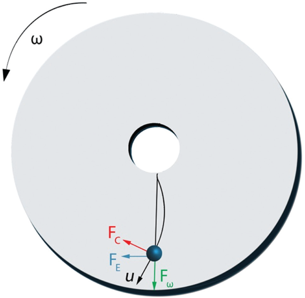
Schematic of forces present on a rotating platform. Fω, centrifugal force; FE, Euler force, which is perpendicular to the centrifugal force; and FC, Coriolis force, which is perpendicular to the velocity.
where ρ is the liquid density,
The Coriolis force is perpendicular to the velocity vector of the moving particle shown in Figure 1 . The force per unit volume is:

where ρ is the liquid density,
The Euler force is perpendicular to the centrifugal force and opposite to the direction of angular acceleration. This force is only generated when the angular velocity of the disc changes with respect to time, and the force per unit volume is:
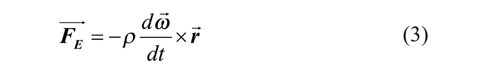
where ρ is the liquid density,
In most cases, only the centrifugal force is used for liquid propulsion. Liquid flow characteristics are dependent on the liquid’s properties (e.g., density and viscosity), its radial location on the disc, the angular velocity of the disc, and the geometry of the microfluidic features. This flow rate was characterized by Madou et al. and Duffy et al., who derived the flow rates of liquids on a LoD platform from basic centrifuge theory.8,9 The average velocity of the liquid on a spinning platform is given by Equation (4):

where
The volumetric flow rate (Q) is defined in Equation (5):

Flow rates achieved experimentally by Duffy et al. had no systematic deviation from the theoretical model and ranged from 5 nl/s to 0.1 ml/s depending on a combination of factors, including rotational speeds of the disc (400–1600 rpm), channel widths (20–500 µm), and channel depths (16–340 µm). 9 Since this early work, higher rotation speeds and greater variation in channel width and depth have been used to achieve flow rates that are significantly higher. 6
Furthermore, Duffy et al. tested flow rates for a variety of different liquids to verify the effectiveness of the centrifugal pumping mechanism when pumping liquids with varying physicochemical properties, such as pH, ionic strength, and conductivity. 9
CD Fabrication
Successful adoption and use of LoD systems depend on inexpensive and reliable manufacturing solutions for the disposable CD. Common materials used for microfluidic discs include, but are not limited to, polycarbonate, poly(methyl methacrylate) (PMMA), cyclic olefin polymer (COP), polydimethylsiloxane (PDMS), and polyurethane. Often, optical detection requires optical-grade materials, which can be costly. These materials can be used for rapid prototyping by molding, 3D printing, laminating, and computer numerical control machining, and some can be injection molded for mass production. For rapid prototyping purposes, microfluidic discs are generally made from layers of adhesives and hard plastics (see Fig. 2 ). 10 Features can be cut into polycarbonate, PMMA, or COP sheets using a milling machine.10,11 PDMS and polyurethane features can be molded using, for example, a wax or SU-8 mold.9,12 PMMA can be cut using a laser, whereas COP and other polymers in thin-sheet form can also be embossed or micro-thermoformed.12,13
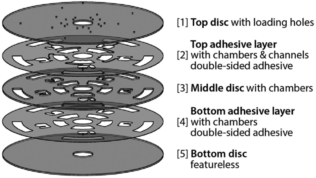
Five-layer disc assembly method. Layers 1, 3, and 5 are typically made from a hard plastic material. Layers 2 and 4 are typically made using a double-sided adhesive.
Other bonding techniques, such as laser bonding, 14 solvent bonding, 15 thermal bonding, 16 and ultrasonic bonding, 17 have been used to bond CD layers together, and these approaches can be scaled up for mass production. Most materials used for CD microfluidics are sufficiently hydrophobic for use in hydrophobic burst valves, which are disc angular frequency–controlled valves. In certain cases when the disc surfaces need to be more hydrophilic, the material must be surface treated using oxygen plasma or a surfactant. However, oxygen plasma treatment adds to the cost of fabrication, and generally, both plasma and surfactant treatment result in devices with short shelf lives.18–21
New solutions to produce more permanent surface treatments that are also compatible with reagents and samples used on the CD are becoming available. Kitsara et al. spun coat polyvinyl alcohol (PVA) and (hydroxypropyl) methyl cellulose (HPMC) on PMMA surfaces, demonstrating a contact angle change from 68° to 22° and 27°, respectively, that lasted for more than 60 days. This surface treatment was tested on a CD device with serial siphon valves, which was previously designed by Siegrist et al., 10 and a sandwich immunoassay was implemented to validate the biocompatibility of the treatment. 22
Future Outlook for CD Fabrication
Although many of the works described in this review use so-called subtractive manufacturing methods, where material is removed to create desired features, the focus has begun shifting to rapid prototyping using additive manufacturing methods such as 3D printing. Despite the geometric distortions that typically accompany 3D printing, Moore et al. showed that the experimental burst frequencies, or the spin frequencies at or above which liquids pass through a burst valve, on microfluidic discs fabricated using this method were comparable to theoretical burst frequencies, proving that traditional CD functions can be implemented on 3D printed disks with similar results for prototyping purposes. 23 This implies that 3D printing harbors further potential for CD microfluidics research. Furthermore, prototyping in CD microfluidics generally uses layers of different materials, making transfer to injection molding in mass manufacturing difficult because fluidic behavior may change with respect to disc materials. Although 3D printing cannot be used for mass manufacturing, it can be used to study fluidic behavior in microfluidic discs with homogeneous material composition.
Although the cost for a high-resolution 3D printer is still high, its advantages over other manufacturing techniques described here include quick fabrication time (<30 min) and ease of fabrication requiring only computer-aided drafting (CAD) knowledge. In addition, 3D printing is appropriate for low-resource environments, where microfluidic diagnostics can be produced and used. Additive manufacturing modules can also be a part of sophisticated, portable manufacturing platforms such as desktop integrated manufacturing platforms (DIMPs) for prototyping or research purposes (for extensive discussion of this topic, refer to the Conclusion section). 24
Fluid-Handling Techniques
Valving Techniques
Effective valving technologies lie at the heart of sample-to-answer assays: keeping a liquid volume isolated from the rest of the system during operations such as sample lysis and mixing, allowing for accurate aliquoting, and preventing liquid leakage during temperature changes, for example.
Valving techniques on centrifugal microfluidic platforms can be classified into three different categories: passive, active, and semiactive. Passive valves do not use any forces besides those present on the spinning disc, and they are actuated by the rotation of the disc itself. The actuation of a passive valve is dependent on the interplay between surface tension and centrifugal force acting on the liquid in the disc. The most common passive valves are burst valves.9,25 When the angular velocity is sufficiently high, the centrifugal force overcomes the surface tension of the liquid, allowing it to burst into the next chamber. For this reason, the angular frequency at which the valve opens is called the burst frequency. Some passive valves are actuated by decreasing the rotational speed of the disc, such as the pneumatic pump (refer to the Passive Pneumatic Valves subsection) or the siphon valve. 3 Another type of passive valve, the Coriolis valve, is actuated by changing the direction of disc rotation. 7 Although passive valves are simple to fabricate, some types require a hydrophilic surface treatment step, usually plasma treatment. 3 This surface treatment is reversible and generally limits the shelf life of the device to a range of days to weeks,18–21 whereas current diagnostic devices remain on the shelf for many months before use. In addition, variations in the manufacturing process can change the burst frequency from device to device, making it difficult to implement a reliable protocol. 22
Active valves require an external actuation mechanism, resulting in higher reliability and robustness than passive valves. The operation of these valves is independent of or only partially dependent on the angular velocity of the disc. Examples of external actuators include heat sources, lasers, and magnets. The main disadvantage of active valving is the need for additional hardware, adding complexity and cost to the platform.
In this review, we define another type of valving: semiactive valving. Semiactive valves are angular velocity-dependent valves that offer a higher level of control than passive valves, yet they are simple to fabricate and do not involve surface treatments. They usually integrate additional inexpensive materials, such as paper, to perform valving tasks.
In the context of valves, it is important to distinguish between liquid valves and vapor valves. When liquid passive valves are “closed,” they do not prevent vapor exchange within the disc’s fluidic network. In contrast, a vapor valve seals off both liquid and vapor, but allows them to pass on opening. Certain vapor valves have long enough shelf lives to be used for liquid reagent storage on the disc, eliminating the need to manually add reagents before running an assay and increasing the commercial value of the device.
Passive Valves
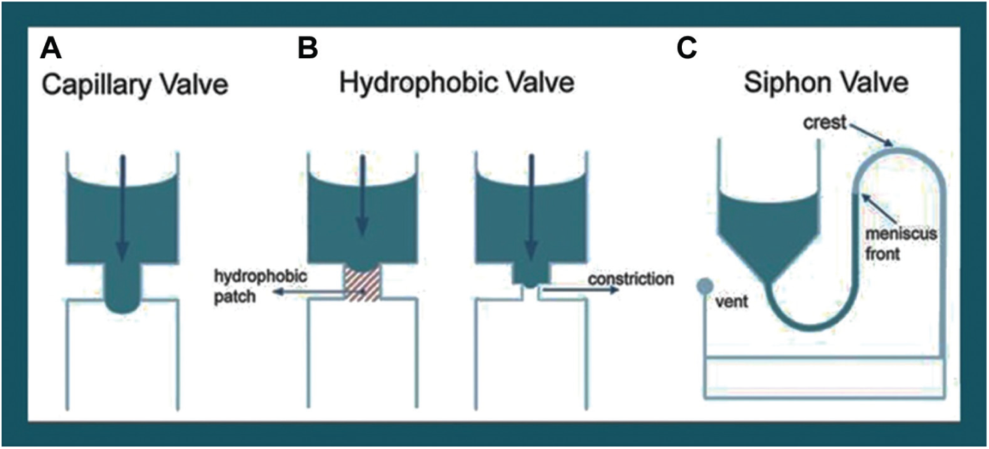
Passive valves remain an advantageous valving technique because of their simplicity and ease of fabrication. Capillary valves were the first type of passive valve to be investigated on LoD platforms, and they are dependent on the interaction between the liquids and the disc materials. When the centrifugal force exerted on a volume of liquid overcomes the capillary force exerted on that liquid by the surrounding materials, the liquid is pushed through the fluidic features outward from the center of the disc ( Fig. 3A ). Thio et al. analyzed several models for predicting the burst frequencies of capillary valves and examined convex menisci that extended beyond the channel opening, taking into consideration the angle with which a channel opens into a larger reservoir. Adjusting the equation parameters to more closely simulate previous experimental conditions has yielded improvements on the agreement between theoretical and experimental data. 26
Lab-on-a-CD passive-valving techniques. (
Another type of passive valve, the hydrophobic valve, is also dependent on the interaction of the liquid with the materials of the disc, and it uses a hydrophobic patch or a constriction in the channel ( Fig. 3B ).3,27–31 An advantage of hydrophobic valves is that they do not require hydrophilic surface treatments, which can be costly and ineffective, as discussed above.
The siphon valve addresses the challenge of process timing in a microfluidic system. A siphon valve, connected to a liquid-containing reservoir, again exploits the interplay of capillary forces and centrifugal forces. At initial high angular velocities of the disc, the liquid level in the channel remains below the crest of the siphon. When the rotational velocity is sufficiently reduced, capillary forces dominate and the liquid fills the siphon, priming the valve ( Fig. 3C ). When the angular velocity is increased again, the hydrostatic pressure difference now aids in the complete emptying of the original reservoir.
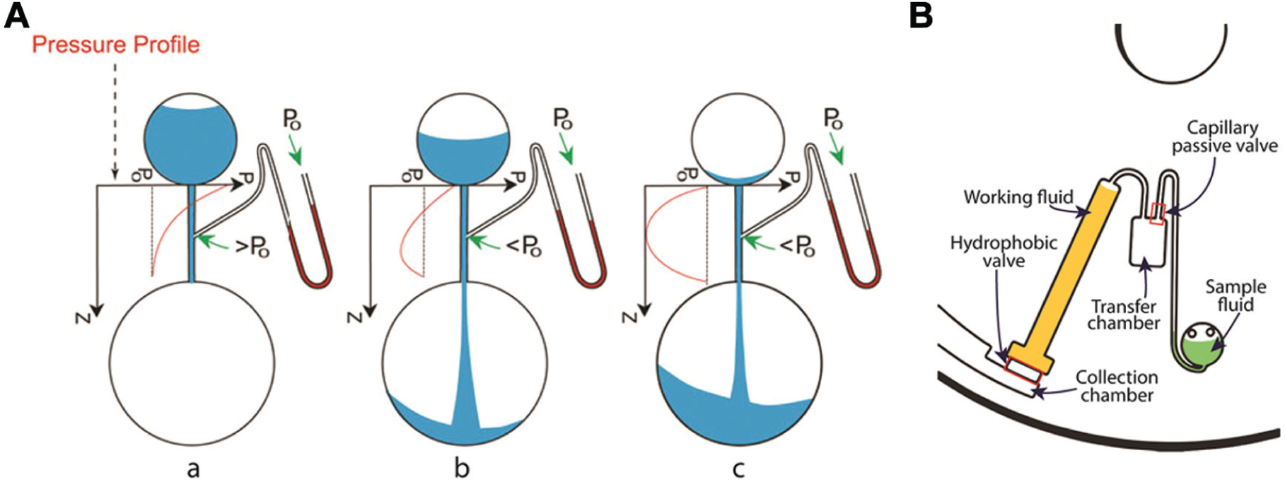
In 2011, Gorkin et al. enhanced this technique by using the bursting of one liquid’s passive valve to release a second liquid stored in an adjacent chamber (see Fig. 4A ). The second liquid’s storage chamber is connected to the first liquid’s exit channel via a hydrophobic siphon. When the first channel is burst, a negative pressure is created that pulls the second liquid over the hydrophobic siphon, draining that chamber due to the hydrostatic pressure in the siphon. This technique does not require any surface treatments and can be used when two liquids need to be pumped sequentially. 32
(
Another modification of the siphon valve is the micropulley valve developed by Soroori et al. 33 For this method to work, a sample liquid is in a loading chamber, which is connected to a transfer chamber where the sample liquid will drain. A second working liquid is loaded in a chamber, where a channel connects the top of the transfer chamber to the top of the working liquid’s loading chamber (see Fig. 4B ). The channels and chamber between the two liquids are ventless. Under high centrifugal force, the working liquid bursts and begins to flow into a collection chamber. The working liquid column and the air between the two liquids behave like the weight and rope of a pulley system, respectively. As the working liquid column height decreases, the expanding air creates a negative pressure that pulls the sample liquid against the centrifugal force toward the center of the disc. 33
Passive pneumatic valves
The centrifugal force points radially outward from the center of a microfluidic disc, making the implementation of more complex LoD systems problematic because liquids cannot be pumped back to the center of the disc. To overcome this problem, methods were developed for pumping liquids back toward the center against the centrifugal force, extending the path length of the fluidic network. In one case, Gorkin et al. used an air compression chamber to pump fluids back toward the center of the disc. 34 Liquid was centrifuged at 7000 rpm to trap and compress air, storing pneumatic energy. When the disc’s angular frequency was lowered, the trapped air quickly expanded, pushing back liquid toward the center of the disc. This cycle of high and low angular frequencies can be repeated to act as a reciprocating pump. A connecting siphon in a pristine disc can now offer the same function as a siphon valve. 3
Taking advantage of pneumatic reciprocating pumping, Noroozi et al. embedded an immunoassay array in a special mixing chamber connected to the air compression chamber of a pneumatic pump. When the disc was spun at high angular velocities, the liquid sample compressed the trapped air and passed over the array in one direction. When the angular velocity was decreased, the sample was pumped out from the mixing unit in the reverse direction. Noroozi et al. compared the efficiency of reciprocating flow, flow-through, and passive diffusion when forming antigen–antibody complexes between human immunoglobulin G (IgG) antigens and goat anti-human IgG antibodies. Reciprocating flow was found to be the most efficient method because it reuses the same sample volume, using only a fraction of the volume required for a flow-through assay. Reciprocating the sample volume also introduces chaotic advection, which reduces the reaction time as compared to passive diffusion. 35
Pneumatic pumping was further improved with the implementation of the latex microballoon pump introduced by Aeinehvand et al. (see Fig. 5 ). The microballoon integrates a highly elastic latex rubber sheet into the CD. As the CD was spun at a high angular velocity, trapped air expanded the elastic sheet outward. When the CD’s angular velocity was lowered, the latex sheet relaxed to its original shape, and the compressed air was released. Although Gorkin et al.’s pneumatic pump requires a very high operational angular velocity, adding a balloon feature to the pneumatic pump lowers the required working angular frequency to 1500 rpm or less, which also lowers the power required for pumping and relaxes the demands on the sealing quality of the CD parts. A high angular frequency may prematurely open valves in other parts of the microfluidic disc, so the low actuation angular velocity in this technology is advantageous. 36 The microballoon pump was also used for assisted siphon priming and liquid transfer.
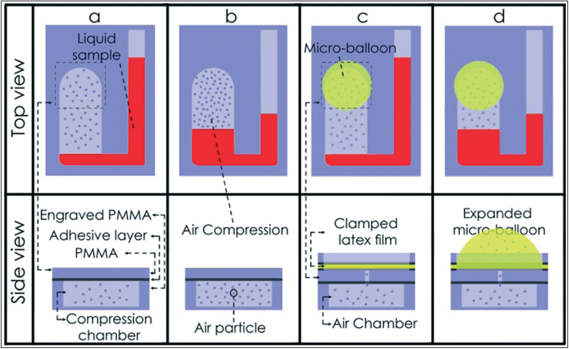
Aeinehvand et al. integrated sheets of latex rubber to improve Gorkin et al.’s pneumatic pumping technique by lowering the angular frequency required for compression. At low angular velocities, the liquid is at the same height without and with the microballoon in (
Zehnle et al. also used a compression chamber to increase the distance over which a fluidic pump can send liquid toward the center of the disc.37,38 The group was able to pump a variety of liquid types from a compression chamber near the rim of a disc to a collection chamber located close to the center of the disc by designing channel geometries to have the appropriate fluidic resistances. A channel with a larger cross-sectional area has a lower fluidic resistance, so the group designed the channel that feeds liquid into the compression chamber to be much smaller than the channel through which the same liquid exits the compression chamber. Although this technique does not guarantee complete liquid volume transfer to the center of the disc, a majority of that volume can be successfully transferred without any external actuation mechanisms or specialized fabrication steps, making this technique useful when a longer fluidic path is required to perform a more complicated assay. A variation on this technique enables thermocycling of the sample liquid, such as in NA amplification, without overpressure. 39
The complexity of many of today’s assays cannot be handled by passive valves alone due to reliability issues associated with their burst frequencies. In addition, passive valves are generally not vapor-tight barriers; this characteristic makes the passive valve unsuitable for reagent storage due to the loss or exchange of vapors throughout time. As a result, other liquid-handling techniques often must be used in conjunction with passive valves to achieve a higher level of fluidic control.
Active Valves
Paraffin wax valves on the CD
Paraffin wax has been a preferred method of vapor valving in chip-based microfluidics due to its biocompatibility and simplicity of operation. It is a phase-change valve, and its convenience and utility are well known.40,41 Only a heat source needs to be turned on to open a paraffin wax valve. Abi-Samra et al. used an infrared lamp to serially open valves made of different melting-temperature paraffin waxes on a CD. 42 The advantage of this technique is that all valves on the same radius of a disc can be actuated at the same time during spinning by positioning the heat source above the desired radial location of the disc.
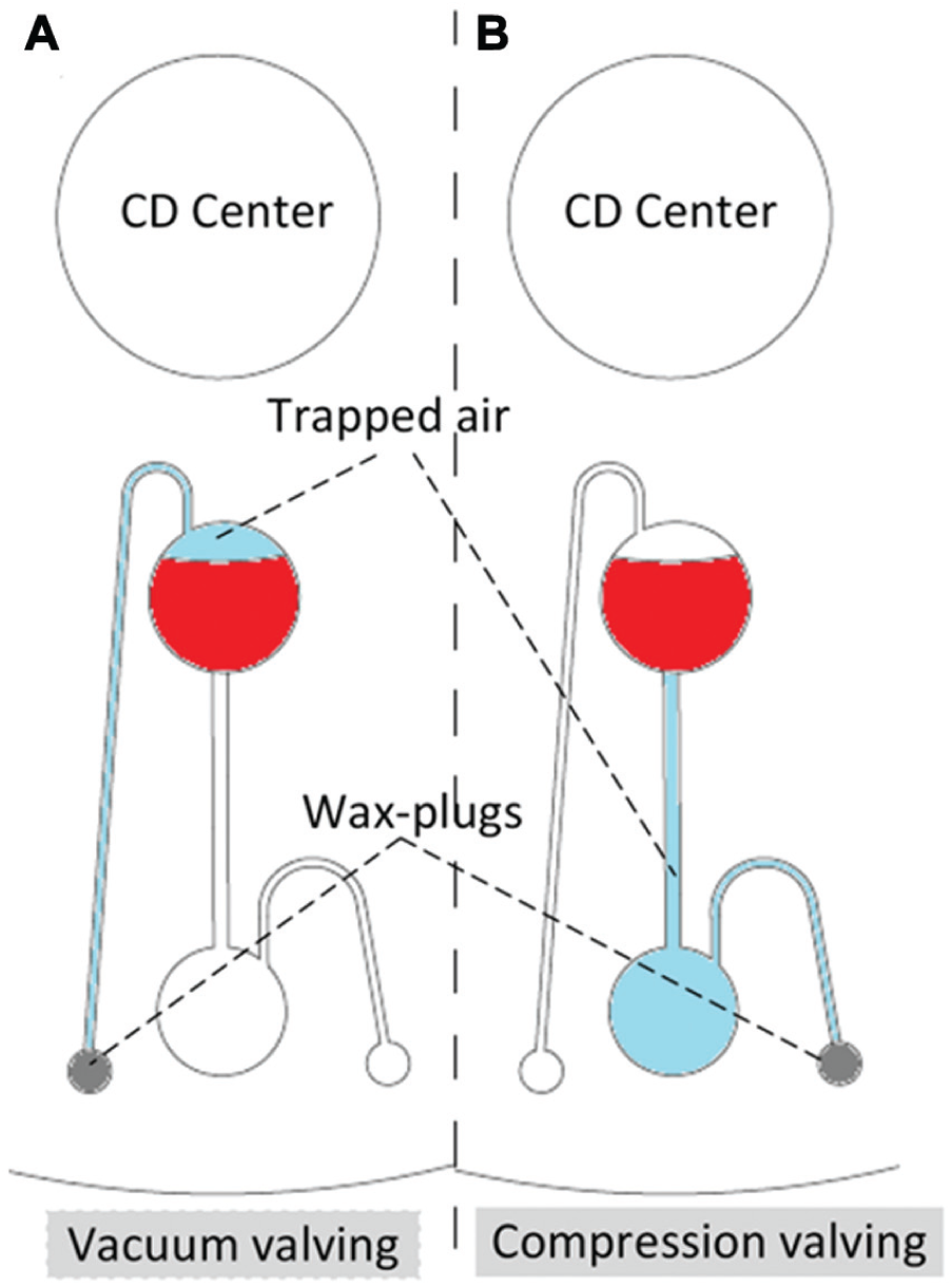
Paraffin valves were also used by Al-Faqheri et al. to achieve vacuum- and compression-controlled valving on a disc. 43 The design (see Fig. 6 ) consisted of source and destination chambers and corresponding vent holes. Vacuum valving was achieved by blocking the source chamber vent hole with paraffin wax, and the trapped air above the sample created a negative pressure that prevented liquid flow to the destination chamber. Melting the wax opened the valve, allowing the liquid to flow to the destination chamber. Compression valving was achieved in a similar manner. In this case, paraffin wax was used to block the vent hole connected to the destination chamber, compressing the trapped air beneath the sample and preventing liquid from entering the chamber. When heat was applied to melt the wax, the fluidic pathway was vented to allow liquid flow. Because the paraffin wax does not provide a physical barrier directly below the liquid, its disadvantage is that under high enough centrifugal force, liquid can leak into the downstream chamber. However, it provides yet another method of on-disc liquid control, and by designing the wax valve to be distant enough from the sample chamber, unnecessary heating of sample and reagents during an assay can be prevented.
Vacuum compression valves. (
Another example of paraffin wax valves, demonstrated on a CD by Park et al., used iron oxide nanoparticles mixed in with the paraffin wax. These valves were actuated by laser irradiation, and the nanoparticles acted as nanoheaters. 44 In this technique, called laser irradiated ferrowax microvalves (LIFMs), as the valves are actuated by a small laser light spot, the probability of exposing the sample to excessive heat is significantly reduced. The disadvantages are that disc rotation must be stopped to actuate the valve and that the actuation of the valves is serial.
Active pneumatic valves
Active pressure-based fluidic techniques provide a simple mechanism to actuate a built-in on-disc pump by expanding an air pocket. Unlike the techniques described in the Passive Pneumatic Valves subsection,32–34,43 active valving and pumping techniques involve external actuation mechanisms and provide more control in fluid-handling.
Abi-Samra et al. demonstrated thermo-pneumatic pumping, which involves heating a ventless chamber of air on a disc. As the air volume thermally expanded, it pushed out liquid in an adjacent chamber. 45 The angular velocity of the disc had to be kept low enough to allow the force generated through thermal expansion to overcome the centrifugal force exerted on the liquid being pumped, while high enough to create a uniform meniscus in the liquid reservoir on which the expanding air can exert pressure. The pumping ability is characterized by the following factors: the amount of temperature change of the air (in accordance with Charles’ Law), the size of the ventless chamber, and the location of the liquid on the disc. A heat source, such as an infrared lamp, is the only piece of external hardware required for thermo-pneumatic pumping.
Pumping using electrolysis was implemented by Noroozi et al., as shown in Figure 7 . 46 A slip ring was used to bring electricity to the CD, and a current was sent through an electrolyte solution using embedded planar gold electrodes. The current generates hydrogen gas at the cathode and oxygen gas at the anode, pumping liquid out of the chamber. Unlike the thermo-pneumatic pump, which limits the volume of liquid that can be pumped with a certain temperature change, a small amount of electrolyte in the electrolysis pump produces a large volume of gas. This pump allows for pumping regardless of its radial distance from the CD center, which is useful when more on-disc real estate is required for an assay.
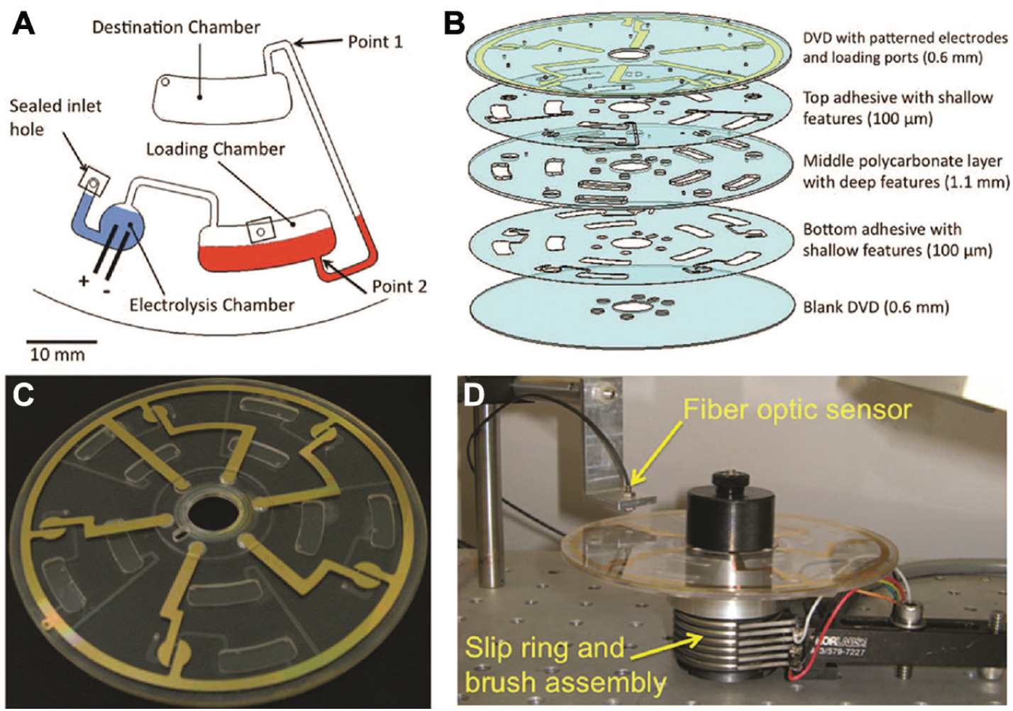
(
Laser-actuated valves on the CD
Optofluidic valves, implemented using plastic sheets and a laser printer, are advantageous because they are easy to fabricate with existing commercial equipment. Garcia-Cordero et al. printed valves as black dots onto a thin plastic sheet sandwiched between two layers of plastic containing overlapping fluidic channels (see Fig. 8 ). The valves were printed at the point of overlap of the channels in the two plastic layers and pierced by a 671 nm, 500 mW laser. Due to laser light absorption by the dark pigment, only the valve material directly adjacent to the printed dot was melted, opening the fluidic pathway. 47 Accidental piercing anywhere else on the device is avoided due to the strict requirement of light absorption for valve piercing. A laser from a commercial optical CD drive can be used to perform serial valve piercing, leveraging existing technology and simplifying the hardware development process. Furthermore, because the valve is liquid- and vapor- tight, and must be opened using a laser, this technology is high in utility and reliability.
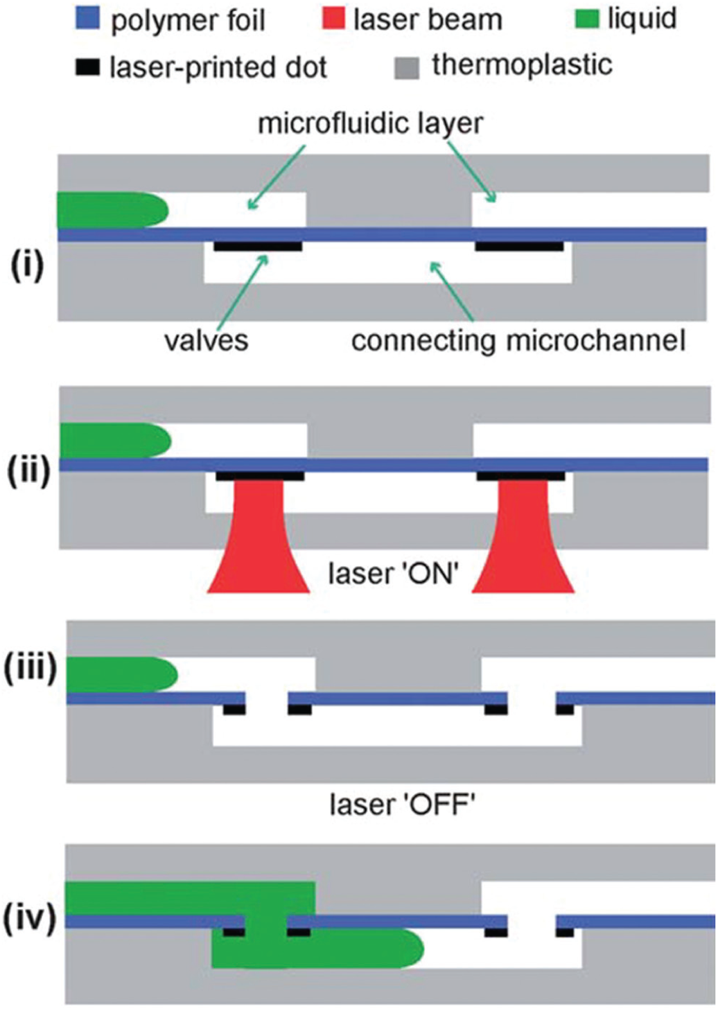
Garcia-Cordero et al. used a 671 nm, 500 mW laser to pierce valves that consist of black dots printed on thin plastic sheets. The operation sequence is as follows: (
Magnetic valving and pumping on the CD
Magnetism as a valving solution on the CD has been explored recently by several groups because of its reliability and versatility. Burger et al. used external magnets to produce a reversible liquid flow inside a microfluidic CD made of a soft silicone elastomeric material, PDMS.48,49 An on-disc magnet was attached to the top of one chamber, and a connecting chamber contained a V-cup array for particle trapping (the pumping mechanism is shown in Fig. 9a–9c , and the V-cup array is shown in Fig. 9d ). The V-cup array chamber was filled with a stationary liquid, and a microbead solution was added via a loading hole. A stationary external magnet was located below the disc at the same radius as the on-disc magnet. When the disc was rotated, the on-disc magnet periodically aligned with the external magnet, pushing the chamber ceiling downward, and propelling the liquid into the V-cup array chamber and toward the center of the disc. The induced hydrodynamic lift forces dislodged the trapped microparticles. Once the two magnets were no longer aligned, the chamber ceiling relaxed, causing a reciprocating flow from the V-cup array to the compression chamber. The behavior of the on-disc magnet was determined by the angular frequency of the CD. A higher angular frequency allowed capture by the centrifugal force, and a lower angular frequency released the captured particles. Integrating an optical tweezer module enabled the transport of individual stain-identified cells to a separate chamber for analysis, which is useful when experiments on individual cells are necessary. 50
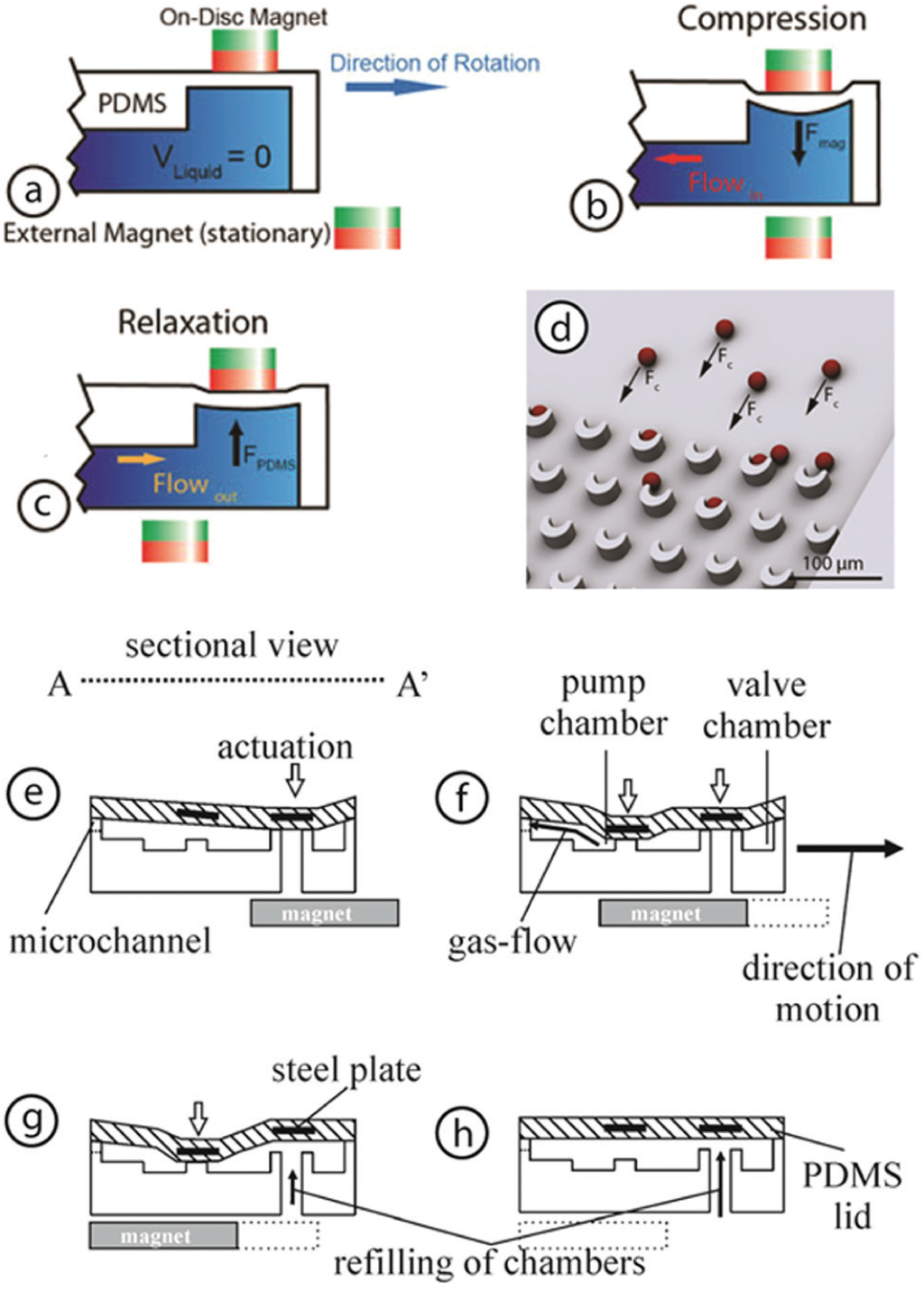
(
This same magnetic-pumping mechanism was applied by Haeberle et al. to develop the centrifugo-magnetically actuated gas micropump, which uses two valves. 51 Two steel plates, each to control a single valve, were directly integrated into a top PDMS layer of a CD. These plates were positioned adjacent to each other but at the same radial distance from the disc center, allowing them to be actuated by a single mounted external magnet. As the plates passed over the magnet during disc rotation, the PDMS ceiling was pulled down, closing the valves sequentially and pressurizing the gas in the chamber. Once the steel plates were no longer above the magnets, the valves were opened, releasing the pressurized gas (see Fig. 9e–9h ). This pressurized gas can be used for pumping liquid streams or for the introduction of ambient air into a liquid sample to implement multiphase flow.
Although this technique was used as a fluid pump by the two groups listed above, the amount of liquid that the pump can transfer is generally limited and depends on the volume of the pump. Another major drawback is that the disc requires the use of a soft material, limiting the material choices. However, in fully integrated systems, this technology can be used to perform other functions such as mixing and requires no external electrical power.
Semiactive Valves
Although only a limited number of approaches have been demonstrated in the category of semiactive valves, these valves can be highly practical due to their low cost and ease of implementation. Passive valves, such as capillary valves, may have a spectrum of possible burst frequencies instead of one absolute burst frequency. Semiactive valves reduce the dependence on the reproducibility of the native surfaces of devices by using an alternative material or a delay mechanism. In systems in which the fluid-handling tasks become more complex, semiactive valves can be added to achieve more robust control than with passive valving techniques alone.
Dissolvable film valve
Valving using biocompatible dissolvable films was first introduced by Gorkin et al. in 2012. 52 In this approach, two chambers were connected with a pneumatic chamber containing a commercially available dissolvable film tab in between, as shown in Figure 10 . Under low rotational speeds, a trapped air pocket prevented the liquid in the upstream chamber from entering the pneumatic chamber and wetting the dissolvable film. Once a high enough rotational speed was reached, liquid entered the pneumatic chamber, dissolved the dissolvable film (DF), and passed into the downstream chamber. The pneumatic chamber, equipped with the dissolvable film, allowed for more control over the bursting event because the angular frequency of the disc must be sufficiently high for liquid from the upstream chamber to enter the pneumatic chamber and begin the valve-opening process by dissolving the film in that chamber. Although this valve is not vapor tight, it provides considerably more control than capillary valves and is tunable in that films with different dissolution rates can be chosen.
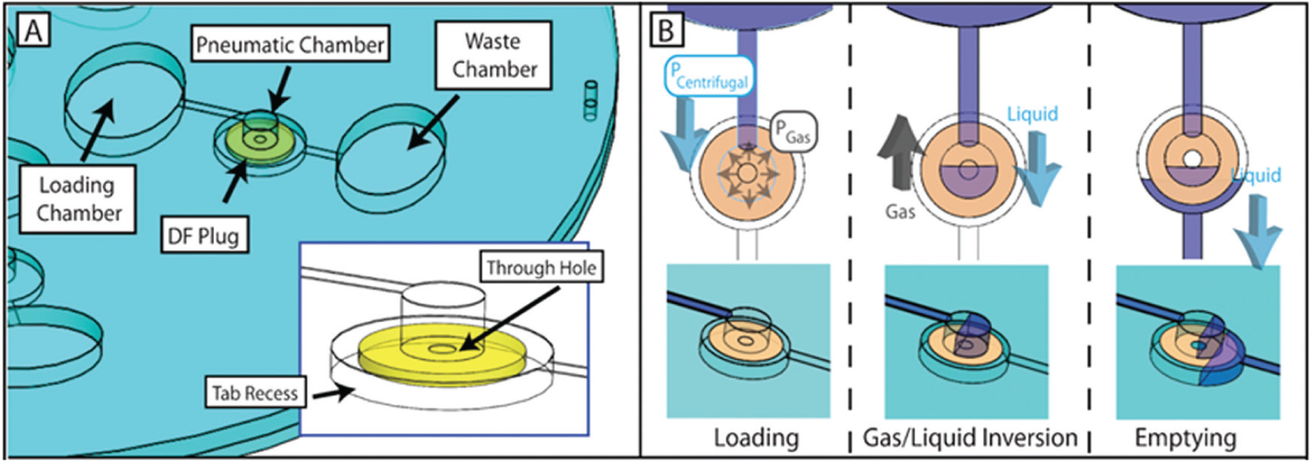
(
A hydrophobic membrane valve can be used in conjunction with dissolvable film to selectively flow aqueous and organic solutions into different chambers.53–57 This technique has been used in combination with paper microfluidics to implement timed fluidic control 58 and has also been demonstrated in clinical applications, including a fluorescence-linked immunoassay and a liver assay panel.59,60
The paper siphon
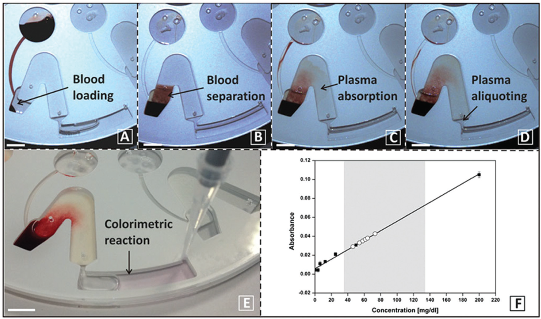
Another type of semiactive valving is established by using paper strips inserted into the CD to perform the function of hydrophilic siphons. Although this type of valving is angular velocity-controlled, the wicking ability of the paper offers more fluidic control than traditional passive valving. The principle of paper microfluidics on a CD is based on the interplay of capillary forces that allow liquid to wick through the paper and centrifugal force that pushes liquid only toward the outer edge of the disc. As shown in Figure 11A–11E , Godino et al. used chromatographic paper in a siphon to achieve a high level of control of blood plasma flow. 61 An aliquoted whole blood sample was spun on a disc to separate blood plasma from the red blood cell pellet. The disc was spun at 375 rpm for 5 min to allow the plasma to wick up the paper siphon and accelerated to 2250 rpm to collect plasma on the other end of the paper siphon. This process was repeated until 10 µL of blood plasma was collected. Figure 11F shows the results of the aliquoted plasma’s triglyceride levels measured off- disc and plotted against a calibration curve. Both dissolvable films and paper microfluidics have been combined in the development of another technology, which involves event-based valve actuation. 58 In this case, the wicking of a liquid across a paper strip opens dissolvable film valves in a desired sequence that determines the fluidics operation.
(
Graphene oxide membrane valve
Gaughran et al. used graphene oxide membranes in flow control of liquids of aqueous and organic phases in a microfluidic disc. 62 The group assembled a 10 µm thick graphene oxide membrane with pressure-sensitive adhesive before assembling it into an 8-layer disc. Characterization demonstrated that the membrane is permeable to water but impermeable to air, isopropanol, and ethanol.
Check valves
Check valves are valves that allow fluid to flow in only one direction. Al-Faqheri et al. implemented several check valves that each incorporated a latex membrane (side views of these valves are seen in
Fig. 12
).
63
As shown in
Figure 12a1–12a3

Al-Faqheri et al. implemented terminal check valves (TCVs) and bridge check valves (BCVs) by incorporating a latex membrane layer in the disc fabrication process. In a TCV (
Similarly, Carpentras et al. proposed a theoretical model for controlling the liquid flow through a channel by using a magnetic ball as a movable plug actuated by an external magnetic field. 64 Various channel geometries and materials were tested for both the valve and the movable plug, and an ideal geometry, a conical PDMS valve seat, was proposed. Although this valve has not yet been used in an application, flow control that is independent of heat or chemicals is useful in temperature- or contamination-sensitive molecular diagnostic assays.
Volume Definition
Volume definition, in some cases called aliquoting, is used to obtain the appropriate volumes of reagents and samples for downstream analysis. Although the simplest way to define volumes is the use of an overflow chamber, 6 many other techniques have been used on the disc. For example, volume definition can be performed by placing a body of liquid inside a chamber with two channels: an overflow channel at the top; and a collection channel, which only opens after the overflow is complete, at the bottom. 65 Volume splitting was implemented by Andersson and Ekstrand, who created a zigzag hydrophilic channel design, geometrically defining a series of volumes before sending each fraction to perform its respective test. 66 This feature can be used to vary the concentrations of the reagents to automatically synthesize different nanoparticles, as shown by Park et al. in an application that synthesizes nanoparticles of various colors, 67 and in another application that synthesizes anisotropic metallic nanoparticles. 68 Optimization of this technique with other functional units in a system can yield high-throughput synthesis of a great variety of nanoparticles for the monitoring of biological or chemical assays.
Decanting from a sample volume, such as a fractionated whole blood sample, has been explored and demonstrated by several groups.65,69-73 Whole blood fractionation techniques are useful when blood plasma is required for its components. The most common way to decant blood plasma from a fractionated whole blood sample is to use a hydrophilic siphon that leads from the bottom of the plasma layer to a collection chamber. At lower spin frequencies, plasma flows out through the siphon, similar to the mechanism of a siphon valve.
One of the most applicable techniques for volume definition for complex assays was demonstrated by Mark et al., who divided a liquid sample into smaller volumes. 74 The feature that this team implemented is shown in Figure 13 and allows a stream of liquid to enter the volume VM while the unvented chamber below, V0, remains empty. The channel between the two chambers prevents the liquid from entering V0 at low spin frequencies because of the air pressure in the chamber. At high spin frequencies, the surface tension is broken, overcoming the high pressure in the chamber and allowing the liquid to enter V0. This technique has been analyzed in detail 75 and is especially useful for performing real-time PCR because defined liquid volumes can undergo thermocycling at high centrifugation speeds with reduced evaporation and no risk for leakage.13,76-78
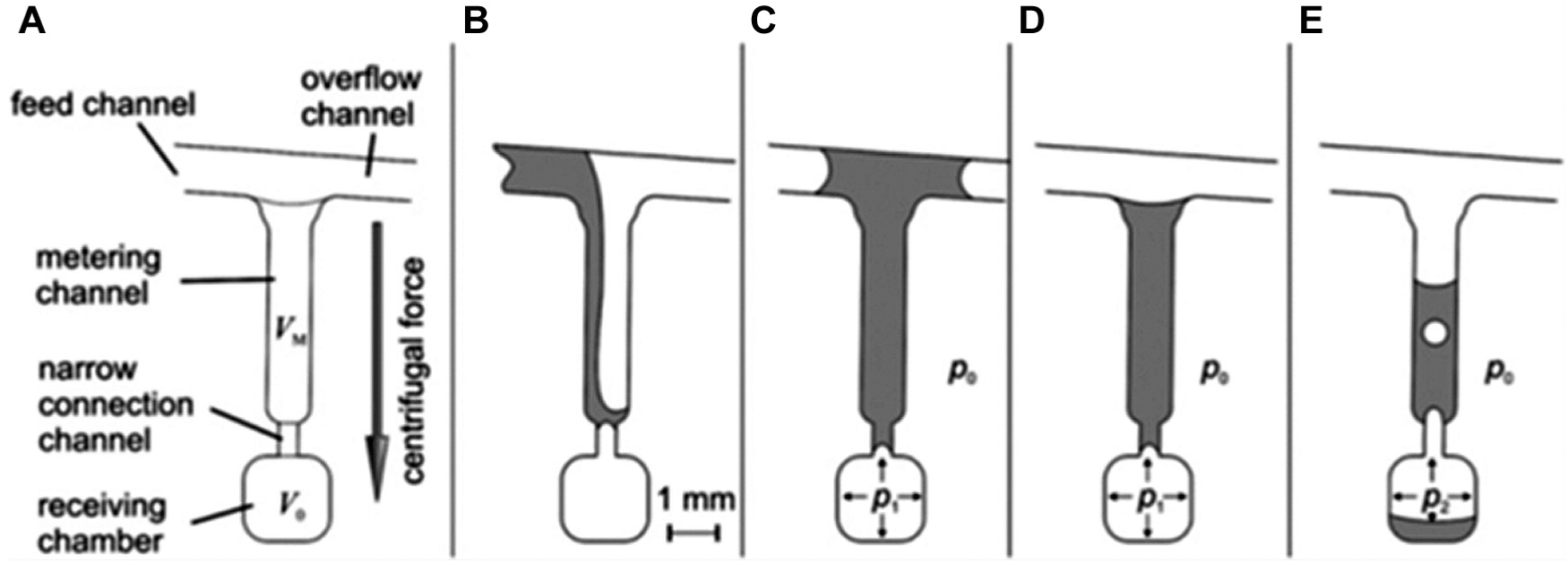
Mark et al. implemented a fluidic feature that essentially incorporates two volumes, VM for metering and V0 for receiving the final volume of liquid (
Mixing
Mixing of reagents and samples is a critical step in any µTAS, particularly in molecular diagnostic processes, in which fully automated fluidic processes in a closed system are crucial to avoid contamination. Although necessary, mixing is challenging due to the low Reynolds numbers and laminar flow regime present in microfluidic devices.79,80 In microfluidic chips, liquid streams are generally confined to narrow channels, allowing for only diffusive mixing. On the other hand, in microfluidic discs, separate liquid streams are usually directed into a large chamber, inducing both convective and diffusive mixing. Although this phenomenon makes the centrifugal microfluidic platform inherently better for mixing, various passive and active mixing techniques have been developed to further speed up the process. Here, we present a variety of mixing techniques for liquid- handling in LoD assays.
Researchers have optimized on-disc mixing by incorporating special micromixers onto microfluidic devices. While passive micromixers use special microchannel geometries to induce advection during liquid-handling and minimize diffusion times, active micromixers use additional hardware or integrated structures to homogenize liquids. One of the simplest passive mixers on a CD is the modified centrifugal force–based serpentine micromixer (CSM) first simulated by La et al. 81 and further optimized by Kuo and Li. 82 A serpentine channel was incorporated into a microfluidic CD design, and the combination of Coriolis force and the channel geometry induced chaotic advection and diffusion in the sample, effectively mixing it. Kuo and Li used the CSM method to mix reagents with plasma after separation by sedimentation, demonstrating the potency of this mixing technique in sample preparation. 82 In Figure 14 , the 5-s time point from the simulation of this micromixer, with different channel widths, is shown.
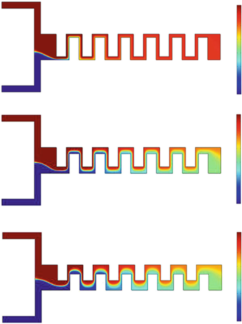
Kuo et al. conducted computer-simulated studies on the effects of a serpentine geometry for a microchannel on a microfluidic compact disc (CD). In this model, the CD platform was simulated to spin at 2200 rpm for 5 s while mixing plasma and deionized (DI) water. The center of the disc is located to the left, and the liquids flow to the right into a waste chamber. The mixing of plasma (red, top inlets) with DI water (blue, bottom inlets) increases as channel width (around the bends) increases. Best mixing is observed in the third simulation where the final product is an intermediate color, or green, to represent a well-mixed solution. (Adapted from Reference 82 , ©2014, Springer.)
Using the same principle demonstrated by Kuo and Li, Aguirre et al. increased chaotic advection by adding an alternating directional flow pattern to the existing CSM. The mixing unit changed the bulk flow direction, resulting in a phenomena called flipping. This method was effective in mixing fluorescent tags with targeted cancer cells in a blood sample. 83
Other passive mixing methods use droplets as microreaction chambers 84 or bubbles to promote chaotic advection. 85 Droplet formation on a disc, in which the small diameter of the microreaction chambers significantly reduces the diffusion distance of any reactants, has been demonstrated by Haeberle et al. 84 Bubble mixing using T-junctions has not yet been integrated on a disc, possibly due to the constraint of the disc’s footprint size, but it could be implemented in the future.
A more effective passive-mixing technique is flow reciprocation, which uses less on-disc real estate than serpentine channels and can be used for sample hybridization. In 2009, Noroozi et al. designed a reciprocating flow mixer that used both centrifugal force and the pneumatic pressure generated in a ventless compression chamber to effectively and quickly mix two liquids together. 86 This technique can handle significantly more liquid sample volume than droplet and serpentine mixing. In 2011, Noroozi et al. was able to integrate this technology into a multiplexed LoD immunoassay to improve Burkholderia detection, illustrating the impact this mechanism can have on sample preparation. 35 Furthermore, Aeinehvand et al. incorporated a microballoon for flow reciprocation. 87 The microballoon mixer required a smaller disc footprint than the reciprocating flow mixer by Noroozi et al. and reduced mixing time from 170 min of diffusion-based mixing to less than 23 s.
Although effective, some drawbacks to passive mixing for more complicated assays include inefficient use of on-disc real estate, long mixing times, and ineffective mixing of very viscous samples. Active mixing techniques include electro-osmotic mixing, 88 ultrasonic manipulation of a piezoelectric diaphragm, 89 and magnetic mixing. 90 Electro-osmotic mixing has not been implemented on a CD due to its dependence on the sample’s pH and ionic strength. 91 Mixing using piezoelectric actuation also has not yet been implemented on a microfluidic disc but could be developed in the future for suitable platforms. Active mixing using magnetic beads is simple and effective, and has been demonstrated on a microfluidic disc by Grumman et al. 92 In this technique, termed batch-mode mixing, a series of permanent magnets were placed at alternating radial distances underneath the mixing chamber, while magnetic microbeads were placed inside the mixing chamber. As the disc was spun, the beads inside the chamber moved toward each permanent magnet, inducing turbulent mixing by means of the Stokes drag force. To further increase mixing, a shaking protocol was implemented, periodically changing the frequency of rotation to induce phases of acceleration and deceleration. This technique creates shear forces that stimulate an advective current during acceleration and deceleration of the disc. This alteration between spinning speeds induces lateral movement of the magnetic beads in the mixing chamber, increasing the mixing area of the beads and drastically reducing the mixing time from 7 min via diffusive mixing to less than 1 s. The mechanical lysis method developed by Kido et al. works using the same principle as the batch-mode-mixing technique. 11 In addition to lysis, it also performs mixing in the same chamber, and has been applied in a NA extraction system developed by Siegrist et al. 94
Future Outlook for Fluid-Handling Techniques on the CD
Although some of the valves described in the valving sections are yet to be used in fully integrated systems on a disc, the availability of different valve options is important for the advancement of new, complex assays. The characteristics of the major CD valving options detailed above are summarized in Table 2 . When choosing a valve for a particular application, many of the factors listed in the table need to be considered for a balanced solution between reliability, complexity, and cost. Active valves tend to be more reliable, whereas passive valves tend to be lower in complexity and more cost-effective. A valve may also share external hardware with other features on the disc to lower the overall hardware cost. An example is the multifunctional wax valves technology developed by Kong et al., in which a single heat source was used for release of a liquid encapsulated in wax, incubation of the liquid, and thermo-pneumatic transfer of the liquid to a collection chamber (see the discussion of thermo-pneumatic pumps in the Active Pneumatic Valves subsection). 95
Characteristics and Examples of Passive, Active, and Semiactive Valves.
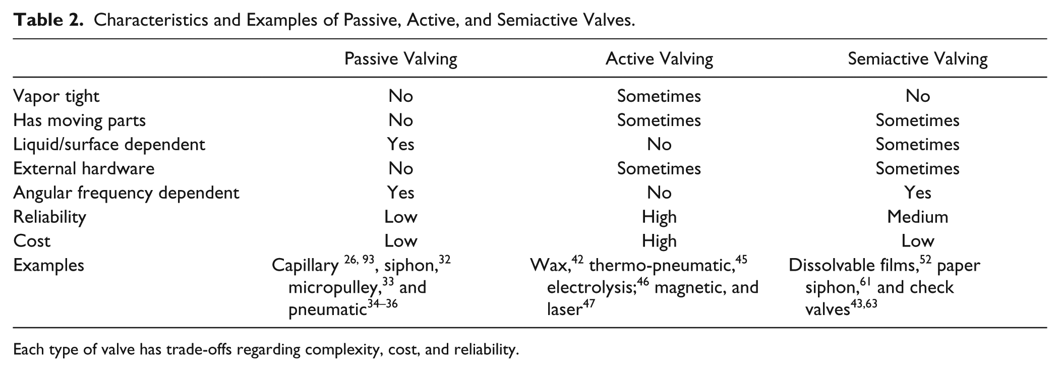
Each type of valve has trade-offs regarding complexity, cost, and reliability.
Although it may seem attractive to use a combination of several fluid-handling techniques in novel sample-to-answer assays, the resulting complexity will often be too high. Reducing such complexity can promote the development of multistep assays on a CD. For example, the most effective mixing techniques use additional mechanical components, such as magnetic beads, to create turbulent mixing. The use of these extra components allows for other operations such as lysis (as discussed in the Cell Lysis section) in the same fluidic chamber, reducing the use of on-disc real estate and decreasing design complexity. Evidently, the need for simpler, lower-cost, and more reliable fluid-handling options is always present.
Reagent Storage
One of the more neglected yet critical aspects of CD microfluidics is long-term, vapor-tight reagent storage and on-demand release of both liquid and solid or dried reagents on microfluidic discs. For a microfluidic assay to be effective, reagent storage must have the following characteristics:
Long-term storage for up to 12–18 months. The quantity and integrity of the reagent must remain sufficient for its respective application before the end of the storage period.
On-demand release of reagents.
Low-cost fabrication and ease of implementation.
Capability to effectively store both lyophilized and liquid reagents on the same disc.
The simplest method of reagent storage is to either dry or lyopholize reagents, turning them into easily resuspendable pellets. 96 However, this method is not vapor tight and may require specified storage conditions. Kim et al. developed an effective method of encapsulating lyophilized reagents in paraffin wax. 97 Heating the wax-encapsulated reagents not only released the reagent but also created a “hot start” effect for enzymes.
Although this works well for solid reagents, some assays use liquid biological reagents or combinations of both liquid and dry reagents. To address the need for liquid reagent storage, Van Oordt et al. demonstrated an effective storage solution that uses pouches made from an aluminum foil composite. 98 These aluminum pouches, illustrated in Figure 15 , were fabricated with a frangible seal. As the disc was spun at a sufficiently high angular frequency, this seal was broken by the hydrostatic pressure from the liquid inside the pouch. The pouches were sealed using ultrasonic welding, and the strength of the seal was tuned so different pouches could open at different disc spin rates. A second frangible seal can be implemented on each pouch to create separate storage compartments for liquid and dried reagents. These pouches were tested to have a volume loss of 0.4% after 42 days at 70 °C, which is equivalent to 2 years at room temperature. In addition to the long-term vapor-tight storage of liquids, this technology can also serve as a semiactive valve.
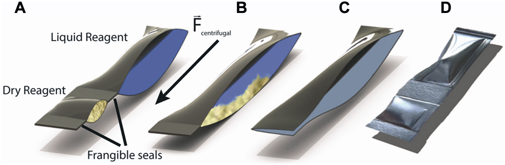
Miniature aluminum pouches used for microfluidic compact discs were made by van Oordt et al. From left to right: (
Although aluminum pouches are well suited for storage due to their versatility and low cost, the best packages for long-term storage of complex liquid biological reagents are bio-inert glass ampoules. 99 Despite the wide use of glass in most biological applications, cost, manufacturing, and safety challenges have prevented it from being used in microfluidic devices. For certain specialized assays, glass is necessary, and new techniques for integration of glass ampoules must be developed. On the other hand, plastic tubes have been successfully used in complex assays by companies such as GenePOC, which seal plastic tubes with a heat-sensitive material for NA amplification. 100 Certain active valves, such as the laser-pierceable polymer valves developed by Garcia-Cordero et al., can also be used to store liquid reagents for up to 30 days with no significant evaporation. 101
Future Outlook for Reagent Storage
Reagent storage, which has been neglected in the field of CD microfluidics, remains one of the most critical components of a complete sample-to-answer system. Future work will focus on two aspects of reagent storage: the development of bio-inert, inexpensive materials for reagent encapsulation and the integration of simple, noncontact reagent release mechanisms that take advantage of the forces present on a spinning disc.
Sample Preparation
In biological and chemical assays, a raw sample must go through a series of preparatory operations, which may include cell sorting or sample concentration, lysis of cells in assays requiring genomic material, sedimentation to isolate any precipitate from supernatant, and filtration. 102 Very few LoC and LoD devices, particularly those that perform molecular diagnostic assays, feature a completely integrated sample preparation system because modular solutions, in which one fluidic feature or hardware component can be used for multiple functions, are rarely available. However, to develop a truly user-friendly and portable total analysis system, sample preparation is key. The physics already present on the rotating platform make it ideal for integration of multiple sample preparation steps on a single platform.
This section describes processes commonly used in clinical assays with a focus on NA processing. Particle sorting, sample purification, or sample concentration is used in any assay in which the species of interest needs to be further isolated, whereas sedimentation or filtration is used to separate components of different densities. Cell lysis is a specialized operation generally used for molecular diagnostic assays. Purification of NAs is required in certain molecular diagnostic assays. 103 A flow chart of the processes in a molecular diagnostic assay is shown in Figure 16 .
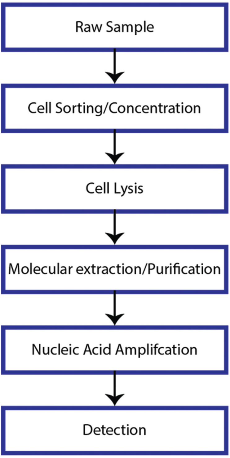
Steps in a typical molecular diagnostic assay.
Particle Sorting
Particle sorting is required when there is a low quantity of a target cell type amongst a population of cells. Such cases include separation of fetal cells from the mother’s whole blood or rare cancer cells from a tissue sample prior to NA analysis.102,104 The size range of particles that can be separated is inherently limited by the radial size of the disc. Even so, effective particle separation on a disc is possible, and it is preferred because the motor for rotating the CD uses a small amount of power compared to any benchtop system.
Particle separation can use either passive methods that take advantage of the centrifugal force or active methods that incorporate external components. Aguirre et al. used Dean forces in serial serpentine flow-focusing channels to separate cell–bead complexes from blood. 83 Morijiri et al. separated particles of different densities and sizes using a rotational movement combined with a technique called pinched-flow fractionation, as illustrated in Figure 17 . The fluidic structure was filled with a bulk buffer solution before the particles were introduced. As the disc rotated, the pinched segment focused particles onto the upper wall, whereas the centrifugal force drove the sedimentation of particles by their respective sizes and densities. 105
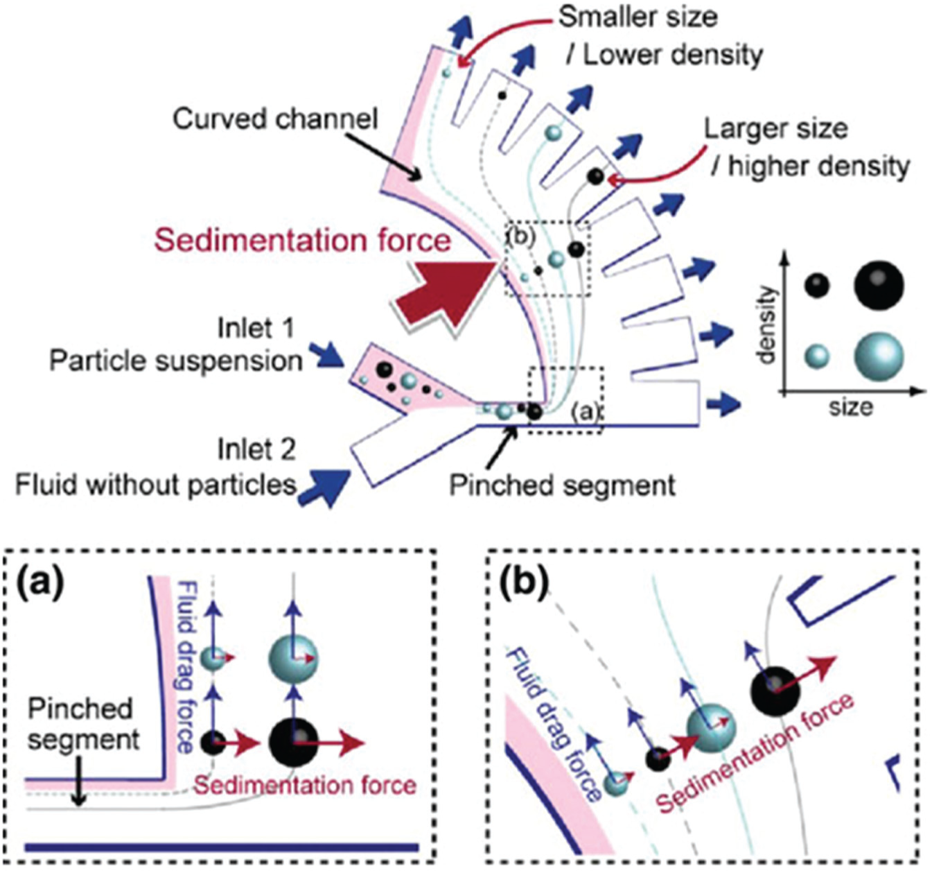
Schematic of pinched-flow fractionation by Morijiri et al. (
Besides using pseudo-forces present on a rotating platform, additional active components may be integrated for more effective particle separation. Recently, Kirby et al. used a set of three magnets on a CD platform to successfully simulate the isolation of rare bioparticles from background tissue cells (see Fig. 18 ). 106 A mixed particle suspension, including magnetic and nonmagnetic particles of different sizes, was sent through a focusing channel, where the centrifugal force, along with three permanent magnets located at different radial distances, separated particles according to their density, size, and magnetic properties. Nearly 100% separation was achieved. This technique was used to separate MCF-7 cells with as few as 1 target cell in 1 µL of whole blood with capture efficiencies of up to 88%. 107 A total of 18 µL of sample was processed on a disc within 10 min.
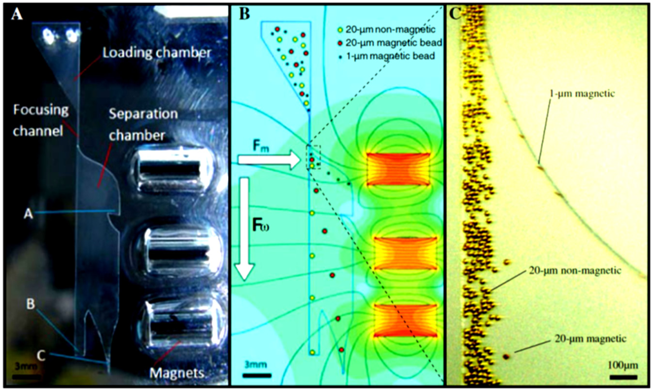
(
Glynn et al. used geometric designs, termed size exclusion rails, to separate cells of different sizes. 108 Whole blood, spiked with HL60, colo794, and sk-mel28 cells, was sorted on the microfluidic disc. The different size gaps in the geometric design allowed the passing of the appropriate-sized cells into several bins. Each bin received cells of a certain size range, including components of blood, making this technique a simple and label-free manner for cell sorting.
Schaff et al. demonstrated sedimentation-based particle sorting, in which two different size and density bead types, each functionalized with a different capture antibody, sediment into distinct layers when passing through a density medium. This process also separated the beads from the red blood cells in the case that they are present, and provided a washing step for the beads. 109 Koh et al. performed a similar sedimentation step with only one bead type for the detection of botulinum toxin and achieved a lower limit of detection of 0.09 pg/mL. 110
Sample Purification and Concentration
The detection of low-concentration components in many biological or chemical assays may require an initial step to concentrate or isolate the sample. Examples of components that require such a process include proteins, environmental pollutants, and NAs. The method of choice for concentration or purification often involves the use of a solid-phase extraction column. We introduce here several methods used to extract compounds: the use of monolith in a microcolumn, 111 in situ detection following the collection of samples in the column,112,113 and the use of hydrophobic membranes and dissolvable films for reagent flow control in silica bead-based RNA purification. 53
Moschou et al. discussed the implementation of such a unit on a microfluidic disc for the extraction of proteins. 111 The disc contained a microcolumn for separation, a fractionation channel to isolate the proteins from the rest of the sample volume, and an isolation chamber for optical detection of the proteins. The group prepared a monolithic column using in situ polymerization by microwaves for efficient sample extraction. Fluorescent analysis of the isolated analyte showed that at least 80 percent of the original 12.4 pmol sample was recovered.
Works from another group used a different microfluidic disc design to detect and quantify elements in water samples 112 and an environmental pollutant. 113 Instead of elution using organic solvents, the authors analyzed the sample directly in the stationary phase in the column. Direct analysis of the column reduces loss of sample by wall adsorption and the amount of harmful organic solvents used for sample extraction. Using laser ablation, Lafleur and Salin found the limits of detection to be between 0.1 and 12 ng for Ni, Cu, V, and Co. 112 Lafleur et al. analyzed the column for fluorescein by fluorescence and absorbance and for anthracene by fluorescence. The limit of detection of fluorescein was 50 ng using both detection methods, and that of anthracene was 20 ng. 113
Dimov et al. introduced the use of hydrophobic membranes and dissolvable films for liquid reagent control in silica bead purification of RNA samples. 53 Although the system yielded considerably less RNA than benchtop methods, it was capable of purifying both mammalian and bacterial RNA.
Mamaev et al. built a fully contained and fully automated system that performs NA isolation and purification on up to 24 samples. The system incorporates lyophilized reagents, leak-proof inlets for sample input, outlets with standard micro test tubes for sample recovery, and hardware components that deliver heat, pressure, and spinning of the motor to perform valving and pumping. Experiments confirmed that the system was capable of isolating genomic material from Bacillus thuringiensis and Mycobacterium tuberculosis cells that were in the concentration range of 102–108 cells/mL and from hepatitis B and C viruses with concentrations of 102–107 particles/mL in plasma. Quantitative PCR was performed using the obtained B. thuringiensis DNA, and the results among the replicates did not vary by more than 10%. The NA obtained from the automated system was compared to those obtained from the manual method, and the two sets of data were almost identical. These experiments confirmed that the platform was reliable for performing NA purification, and the authors project that, when integrated with low-density hydrogel microarray technologies, the platform will be capable of analyzing viral and bacterial DNA and detecting genetic point mutations associated with cancer or other conditions. 114
Despite the effectiveness of solid-phase extraction for sample purification and concentration, a few challenges still prevent its widespread implementation on centrifugal microfluidic systems. One challenge is the requirement for liquid reagent storage for a fully automated assay. In the multistep elution assays described, the reagents had to be manually introduced into the disc after each step.53,111 A second challenge is the incompatibility of the reagents with the materials used to make the disc. For example, Moschou et al. observed that glycidal methacrylate and hexane, components used to create the microcolumn monolith precursor, caused deformation of the disc’s PDMS layer. 111 In other cases, organic solvents, such as acetone or methanol, are sometimes the standard reagents for an assay. These solvents etch certain polymers such as polycarbonate or acrylic, limiting material choices.
Sedimentation and Filtration
Sedimentation and filtration are essential in assays in which solid portions of the sample may disturb the fluidic process. The inherent centrifugal force on a centrifugal microfluidic platform promotes convenient, built-in sedimentation and speedy filtration. Various aspects of these processes have thus been explored on a microfluidic disc.
One application of sedimentation, blood plasma separation, has been demonstrated in a variety of ways: by exploiting the density and size differences between cellular blood components and plasma,65,69,71,115 by using curved microchannel geometries, 116 and by using special finger-like fluidic structures that increase the bonded area, and therefore, the structural integrity of the disc during large-volume blood plasma separation. 70 A technique for rapid separation of red blood cells from plasma by Kim et al. used inclined chamber walls in addition to centrifugal force, in which a phenomenon called the Boycott effect is observed. 117 According to the Boycott effect, in a gravitational force field, particles suspended in a liquid settle toward the inclined wall, rather than the bottom, of a tilted container, shortening the total sedimentation distance and time. Kim et al. were able to separate red blood cells from plasma in whole blood up to eight times faster in inclined chambers than radial chambers. This effect was further described and mathematically analyzed by Schaflinger. 118 It was demonstrated on a disc in two cases—by Kim et al. 119 using chambers with radial geometry and by Kinahan et al. using chambers with spira mirabilis geometry. 120 Decreasing the width of the separation channels or increasing the inclination angle of channels from the radial direction increases the speed of the blood plasma separation process.
Sedimentation of soil samples has also been demonstrated by LaCroix-Fralish et al., who integrated capillary tubes with very small inner diameters (ranging from 12 to 100 µm) that many microfluidic disc prototyping methods have not been able to accomplish. 118 The capillary tube overreaches into the sample input reservoir, allowing sediments to fall around it and liquid to empty through the capillary tube.
Filtration is a necessary process to isolate components suspended in liquids and can be rapidly performed on a disc due to the presence of the centrifugal force. Lee et al. used a polycarbonate membrane with 8-µm pores to filter MCF-7 cells from whole blood. On average, 3 mL of blood took 20 s to filter without significant radial sedimentation of red blood cells. The group was able to achieve 61% capture efficiency, whereas under different dilution factors, they achieved between 44% and 84% capture efficiency. 104 Karle et al. implemented an axial centrifugal filter on a disc to send liquid, termed permeate, down in the direction parallel to the spinning axis through a filter unit, whereas bacterial cells in the portion of the sample, termed retentate, avoided the filter and flowed toward the rim of the disc. 122 This strategy prevented the clogging of the filters. Templeton et al. sealed different types of filter paper onto polycarbonate layers to create leak-free filtration units and filtered soil from water in <1 min using centrifugal force. 122 Whereas filtration can isolate species suspended in solution that sedimentation cannot, sedimentation is generally preferred on the centrifugal microfluidic platform for two main reasons: sedimentation does not require any extra fabrication steps, whereas filtration may involve insertion of filtering units; and, moreover, filters can be clogged if the amount of precipitate is considerable.
Cell Lysis
For many biological samples, lysis is necessary for retrieving genomic or proteomic material from cells. The process usually involves breaking the outer membrane of the cells using one of two methods: physical means,11,123,124 such as laser-induced thermal shock 72 or sonication, or chemical means, which generally involves the use of detergents. 2 Many of these processes can also perform sample homogenization to ensure that the biological sample is uniform in size and texture throughout.
Although a variety of methods can be used for sample lysis on the CD, bead beating, developed by Kido et al., remains the most universally effective method, capable of lysing even the toughest samples. 11 The bead-beating setup consists of several permanent magnets located under the disc at alternating radial distances. A ferromagnetic disc is free to move inside a radial chamber on the CD. As the CD spins, the ferromagnetic disc moves toward the permanent magnets as it passes them, sliding back and forth in the chamber. Glass beads or another grinding media is required to lyse cells. This method was used to effectively lyse Saccharomyces cerevisiae cells, which are considered notoriously difficult to lyse.
Future Outlook for Sample Preparation
Sample preparation steps may include isolation of specific targets, sample purification, and control of particles inside a liquid solution. The unique nature of the centrifugal platform makes it excellent at realizing many of these applications. Most techniques on this platform do not require any complex fabrication methods, surface treatments, or external hardware components and are capable of dealing with any sample type. To further simplify assays, one set of hardware can be used to accomplish multiple actions, such as the use of the bead-beating setup for simultaneous mixing and lysis of a sample-reagent mixture.
Particle separation has not been integrated into a LoD system with other types of sample preparation units due to its large on-disc real estate requirements. However, with pending applications such as cell sorting for disease diagnosis and wastewater analysis, sedimentation and particle sorting are subfields that continuously seek improvements for more efficient and inexpensive solutions. 125 Future improvements will include the integration of compact particle separation units with other fluid-handling operation units.
To address the challenge of integrating multiple sample preparation steps on a disc with limited real estate, a 3D architecture can be used to combine and organize different modules and reactor systems of the assay. The microfluidic disc created by Ukita et al. provided an elegant solution for performing various functions on a multilayer stacked CD. 126 The different layers of the stack segregated the different steps of the assay and provided several advantages: The increased reaction surface area improved the immobilization of antibodies, the increased total thickness of the disc layers provided a longer optical path length for detection, and a single reservoir of reagents on one layer dispensed reagents to multiple locations on multiple layers. The use of this 3D architecture is a possible solution for sophisticated sample-to-answer assays that require increased fluidic control.
Nucleic Acid Amplification
Nucleic acid (NA) amplification is an integral part of genetic analysis, allowing for the detection of a few copies of biomarkers, which is especially valuable when attempting to diagnose a disease in its early stage. One of the most commonly used techniques for NA amplification is PCR, an enzyme-driven reaction that amplifies a sequence of target DNA by cycling between specific temperatures. For certain other cases in which the sample consists of RNA strands, reverse transcriptase PCR (RT-PCR) is required. In RT-PCR, strands of RNA are transcribed into their complementary DNA (cDNA) before these cDNA strands are amplified with PCR. PCR generally cycles between three target temperatures, each with a specific function–denaturation of double-stranded DNA at 95 °C, annealing of oligonucleotide primers to template DNA strands (the typical annealing temperature is a few degrees below the melting temperature of the primer template), and elongation, or primer extension, which is typically at 72°C. 127 Generally, up to roughly 40 cycles are required to achieve sufficient target NA concentration.127,128 The exact temperature protocol must be optimized for each sample and each set of reagents and equipment used. In general, the main time-limiting steps are the long ramping times between the target temperatures, especially with large liquid volumes. Furthermore, large temperature changes lead to substantial power consumption and generally require bulky hardware.
Thermocycling for NA Amplification
To address the challenges of slow temperature cycling times and high power consumption, PCR thermocycling has been incorporated on miniaturized centrifugal microfluidic platforms. By increasing the sample’s surface area–to-volume ratio, a larger area of the sample is exposed to temperature gradients, yielding faster thermocycling times. Moreover, using smaller components decreases power consumption.
One of the first uses of PCR on a centrifugal microfluidic system was by Kellogg et al., who amplified Escherichia coli DNA. A thermoelectric element embedded in a spinning printed circuit board was in direct contact with the thermocycling chamber on the microfluidic disc, and an integrated thermistor was used for temperature feedback control to achieve a ramping rate of 2 °C/s for a 25 µL reaction volume. 129 The disc was spun to minimize loss of sample volume so that liquid that condensed upstream returned to the PCR chamber. Contact heating has since been used for effective and fast PCR thermocycling by Amasia et al., who used a stationary disc and ice valves for vapor-tight sealing of the PCR chamber during thermocycling.16,130 The design by Amasia et al. used thermoelectric elements for heating, cooling, and valving (shown in Fig. 19 ).
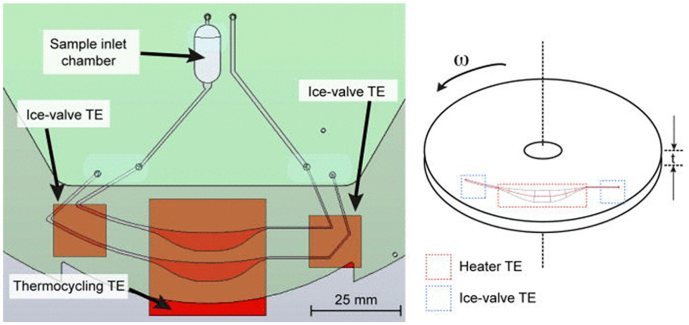
Diagram showing Amasia et al.’s integrated compact disc (CD) setup. Two thermoelectric elements act as ice valves to seal the PCR chamber, and one large thermoelectric element performs thermocycling for PCR. A sample is pipetted into the inlet chamber and is transferred into the inner PCR chamber. A second fluid, used as a negative control, is pipetted into an inlet and is transferred into the outer PCR chamber. Once the samples are inside the PCR chambers, the disc is stopped and the ice valves are turned on, sealing off the chamber. Following this, thermocycling is performed. (Reprinted with permission from Reference 130 . ©2012, AIP Publishing LLC.)
Noncontact heating was first used by Mårtensson et al., who used an infrared (IR) lamp positioned directly above the PCR chamber on a rotating disc to actively heat liquids to desired temperatures. 131 While spinning the disc, both centrifugal and Coriolis forces contributed to the increased circulation and temperature homogenization of the sample. Passive cooling was implemented by fast spinning of the disc. A single cycle time of 20.5 s was achieved for a 100 µL sample, with 45 cycles of PCR finished within 15 min. The method of using pseudo-forces on a disc for temperature homogenization of a sample, called SuperConvection (TM), was patented by AlphaHelix Molecular Diagnostics AB.
Burger et al. used an IR thermocycler with an integrated on-disc wireless temperature system to improve noncontact heating. 132 The group obtained a heating rate of 5 °C/s with a proportional-integral-derivative (PID) controller by optimizing the disc materials and depth of the sample-holding cavity.
Another technique for NA amplification, reported by Sundberg et al., is digital PCR, a method used to quantify genomic material in a sample. 133 In digital PCR, a sample is diluted and distributed into small chambers so that each vessel has either one or zero copies of DNA strands present. After distribution, PCR is performed, and dyes that bind to double-stranded DNA are added. An optical reader then determines whether the result of each reaction chamber is positive or negative, so that the number of genomic templates from the original sample can be inferred. Sundberg et al. used a disc with 1000 nanoliter-sized wells into which the sample was aliquoted (shown in Fig. 20 ). The small volumes allowed for 45 thermocycles to be performed in just 25 minutes.
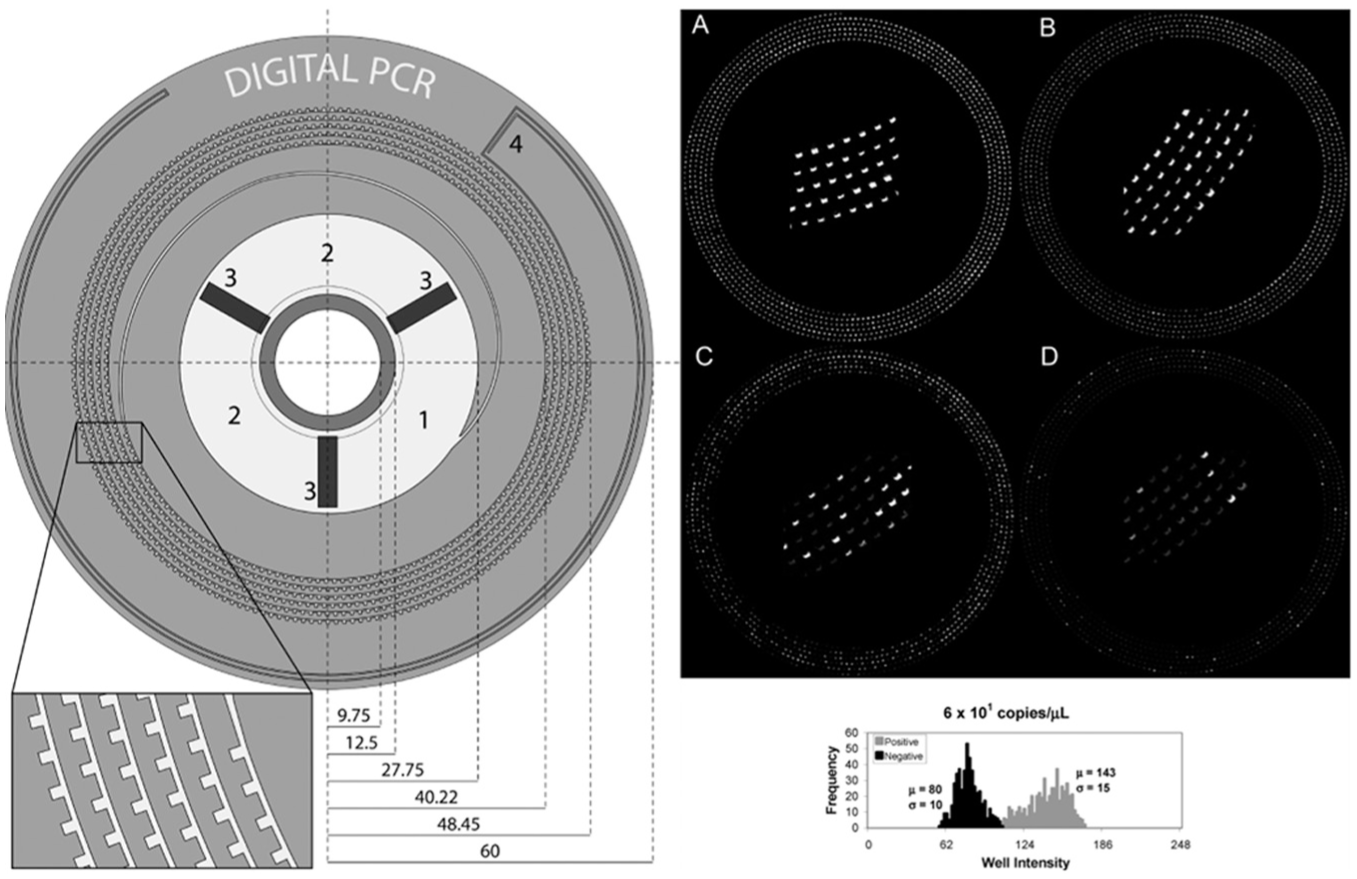
Sundberg et al. designed a microfluidic disc containing 1000 nanoliter-sized wells to perform digital PCR (left). The DNA sample was diluted so that each well contained one or zero copies of DNA. The end results were imaged with a charge-coupled device camera, and ImageJ was used to analyze the wells (right). (Reprinted and adapted with permission from Reference 133 ©2010, American Chemical Society.)
PCR thermocycling times can be further optimized by using droplets on a CD, which significantly increases the surface area–to-volume ratio. 84 Wang et al. used density difference pumping to move a 3 µL droplet between two thermo-electric elements held at different temperatures, 95 °C and 60 °C, for performing real-time PCR. 134 A single cycle time of 60 s was reported. However, despite the success of droplet thermocycling, it should be noted that there is a trade-off between amplification efficacy, which is usually better with more accurate temperatures and therefore slower run times, and fast thermocycling, which risks temperature overshoot.
Future Outlook for NA Amplification
Currently, NA amplification is the rate-limiting step in biomarker detection assays on centrifugal microfluidic platforms, requiring complex thermocycling hardware, specialized sample preparation steps, and solutions to reduce sample evaporation and CD delamination. There are two main future directions for NA amplification on a CD:
1. Hardware optimization: Although both contact and noncontact heating methods (summarized in the Thermocycling for NA Amplification subsection) have been demonstrated for PCR thermocycling, further improvements in heating and cooling ramping rates still need to be made. Techniques implemented while the platform is spinning are preferred, because sample evaporation is reduced as condensate is collected back into the reservoir. 95 More concentrated efforts to improve temperature control and to decrease the complexity and power requirements of hardware used in noncontact heating methods on CDs must be made.
A good example along these lines, although not specifically used for NA amplification, is by Chen et al., who wirelessly heated localized areas on a spinning disc using micropatterned resonant heaters by controlling the frequency of the external radiofrequency (RF) field. 135 This team used inductive heating to achieve temperatures as high as 93 °C. These heaters are low cost and can be selectively activated, and the target heater temperature can be easily adjusted by varying the RF power output, making it an ideal technology for PCR applications.
2. Advanced isothermal amplification techniques: Although PCR has been historically favored for NA amplification due to its potency for achieving the highest sensitivity and accuracy, isothermal amplification methods, which eliminate the need for temperature cycling, have been developed since 2000 136 and have improved throughout time. The sensitivity levels of isothermal amplification methods have been refined to come close to those of PCR.137–139
Examples of isothermal DNA amplification methods include recombinase polymerase amplification (RPA),13,140,141 loop-mediated isothermal amplification (LAMP), and nucleic acid sequence-based amplification (NASBA). These techniques use simpler and less expensive hardware, making them ideal for use on LoD platforms. An example of isothermal PCR on a CD is the recent use of RPA in a lab-on-a-foil disc system by Lutz et al., who achieved amplification at room temperature in less than 20 min with a 10 µL sample volume. 13 This is a good starting point for future NA amplification assays that are both fast and effective.
Analyte Detection Strategies
Two methods of analyte detection have been used on LoD systems: optical detection and electrochemical detection. CD microfluidics, inspired by conventional CD players, has generally preferred optical detection schemes. Although molecular diagnostic assays generally use fluorescent methods, colorimetric methods for the detection of other analytes are also described. Colorimetric methods for the detection of NA biomarkers have not yet been implemented on a disc and are discussed in the Future Outlook for Analyte Detection Strategies section. In addition, recent advances in the microfabrication of electrodes have made electrochemical detection an attractive option for microfluidic devices. This section highlights the recent advances in these two detection schemes and suggests potential future developments for LoD systems.
Optical Detection
Fluorescent detection
Fluorescent detection methods, unlike colorimetric detection, do not depend on the optical path length of the sample, contributing to the enhanced lower limit of detection of the method. For example, Duffy et al. used fluorescence to detect 2000 times lower concentration of a substrate, p-nitrophenol phosphate, than using colorimetry in the same sample volume. Fluorescence has been used successfully in conjunction with the centrifugal microfluidic platform for a wide range of applications, including solid phase extraction, 113 analysis of PCR assays,13,133 and immunoassays.142,163
In molecular diagnostics, DNA microarray hybridization is commonly used in NA detection, particularly when high-throughput analysis is required. On a microfluidic disc, Peytavi et al. implemented a diagnostic microarray for the detection of the DNA of four staphylococcal species. Flow-through of the sample through the microarray was found to be a more effective method for the hybridization of the target DNA strands with probes, as opposed to passive hybridization.143,144 This has been the only DNA microarray implemented on a CD. Burstein Technologies developed a viable strategy using a laser in a CD drive to detect hybridization on DNA microarray. 2 After streptavidin-labeled microspheres were added to hybridized spots, positive spots reflected laser light back to the CD drive’s optical sensor. Other fluorescent detection methods for NA targets have been discussed extensively by Epstein et al. 145
Riegger et al. enhanced the sensitivity of fluorescent signals by using detection antibodies tagged with special fluorescent polystyrene microspheres, called FluoSpheres, that amplify a fluorescent signal by two orders of magnitude. 139 The efficiency of this disc-based fluorescent assay was enhanced by rapidly hybridizing the sample and probe using centrifugal force and by detecting several biomarkers on one device.
Fluorescent detection is generally done with a stationary disc, forcing the user to stop the disc and manually align it to the camera to perform detection. To solve this problem, Ukita and Takayama developed a stroboscopic optical setup to image fluorescent objects on a spinning platform. 146
Despite their success, flourescent detection has one major drawback: the results for fluorescent imaging, traditionally obtained visually through a microscope, can be subjective. To automate fluorescent image analysis, Sundberg et al. implemented a digital PCR assay (described under the Thermocycling for NA Amplification subsection and shown in Fig. 20 ). The disc was imaged by a fluorescent reader, which consisted of a light-emitting diode, a band-pass filter, a lens, and a charge-coupled device camera. Although the acquired results were analyzed with ImageJ software, 133 digital PCR assays involve more objective image analysis that can be fully programmed easily, implying that the entire assay eventually can be automated.
Moreover, due to the high cost of optical hardware, research groups have presented more cost-effective alternative solutions. To substitute expensive glass lenses, Kuo et al. fabricated a microfluidic disc with a built-in PDMS lens for focusing the excitation source. 147 Lutz et al. described a microfluidic disc for isothermal amplification that was operated using a modified commercial thermocycler, the Rotor-Gene 2000 (Corbett Life Sciences, now Qiagen, Sydney, Australia), which was also capable of reading real-time fluorescent signals. 13 Adapting an existing machine reduces the cost and eliminates the need to develop and produce new hardware.
Colorimetric detection
Colorimetry is a widely used technique in many biological and chemical assays for detecting the concentration of specific analytes. The analyte concentration is determined by measuring the absorbance of light of specific wavelengths when a probe beam is passed through a sample holding chamber of a specific thickness. Absorbance (A) is linearly proportional to the concentration of a substance in a solution (c) and the optical path length of the solution (l), according to the Beer-Lambert law shown in Eq. (6):

where ε is the molar absorptivity of the sample.
Because the optical path length in a microfluidic device is typically very short, the sensitivity of colorimetric detection can be compromised severely. Rather than sending a light beam perpendicular to the surface of a flat disc, Grumann et al. designed parallel V-grooves on both sides of the detection chamber to guide a laser beam through the length of a fluidic chamber parallel to the surface of the disc (see Fig. 21 ). The geometry of the chamber is designed to take advantage of the principle of total internal reflection, ensuring that no light is lost, and the entire light beam is reflected throughout the path length of the sample. This setup achieved a fivefold increase in the path length. The disc can continue to rotate while the colorimetric assay is executed, requiring no disc alignment to optical hardware and enabling real-time detection. The enhanced sensitivity of the method has been shown to be comparable to standard colorimetric, cuvette-based assays, such as those for alcohol, glucose, and hemoglobin levels in serum and whole blood.65,124,148,149
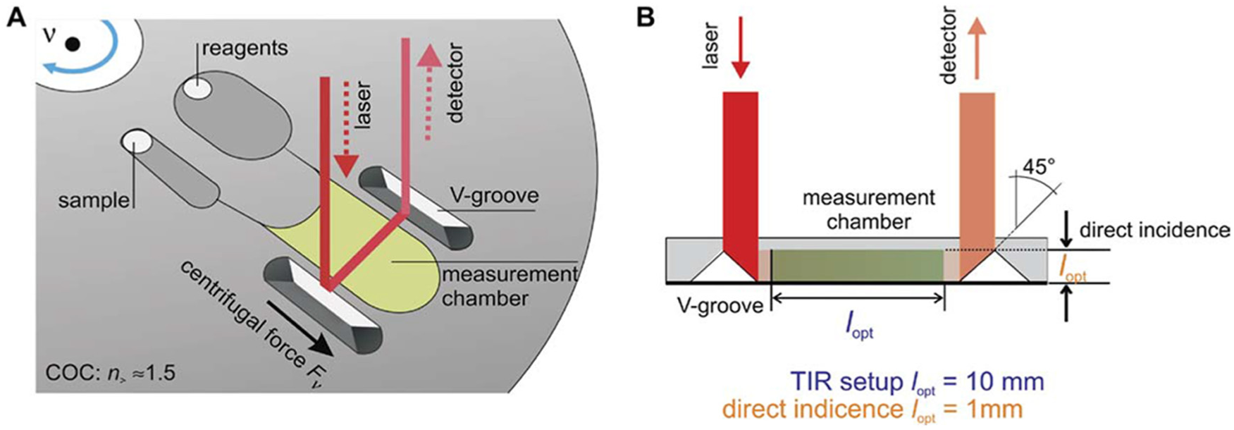
This system developed by Steigert et al. features two V-grooves on either side of the detection chamber. After the sample and the reagents are sent to the detection chamber by spinning the disc, a laser beam is pointed at one of the V-grooves for detection (
Electrochemical Detection
Electrochemical detection is an attractive alternative to optical detection because of its low cost, small equipment footprint, high sensitivity, specificity, and portability.150–152 The most common type of electrochemical detection used in microfluidic systems is amperometric detection.150,153,154 In amperometric detection, the current produced with either the reduction or oxidation of an electroactive species is monitored.
Amperometric detection has been successfully integrated onto the LoD platform using a slip ring-and-brush setup 46 or a low-noise slip ring with liquid mercury for moving electrical contact. 155 In this detection scheme, three electrodes are typically used: a working electrode, a reference electrode, and an auxiliary electrode. An electrical potential is applied between the working electrode and the reference electrode. At the appropriate potential, a redox reaction occurs, and a current is generated. This current, measured between the working and auxiliary electrode, is directly proportional to the concentration of analyte being measured, and the voltage potential, measured between the working and reference electrodes, can be used for inferring the presence of a specific analyte in the system. 156
One application of this method is the detection of proteins or antigens in bodily fluid based on the redox reaction of a substrate bound to the target proteins or antigens. Kim et al. recently used this method to detect C-reactive protein (CRP). 154 This electrochemical method can be used to replace the optical component of standard ELISAs, reducing the footprint of the system.
Another application of an electrochemical measurement is on-disc flow monitoring. Abi-Samra et al. determined the average volumetric flow rate by measuring the current of a ferrocyanide solution flowing over an embedded electrode array (see Fig. 22 ). This method is called flow velocimetry. Ferrocyanide flowed from the loading chamber across the electrode array and into a collection chamber using centrifugal force. Because the flow of the solution enhanced the mass transfer of the electroactive species to the surface of the electrode, an increase in current could be observed as the flow rate increased. The current measured across the electrodes was determined to be proportional to the flow rate across the electrodes. 157 This powerful electrochemical technique uses no bulky hardware or expensive setups, making it ideal for portable applications.
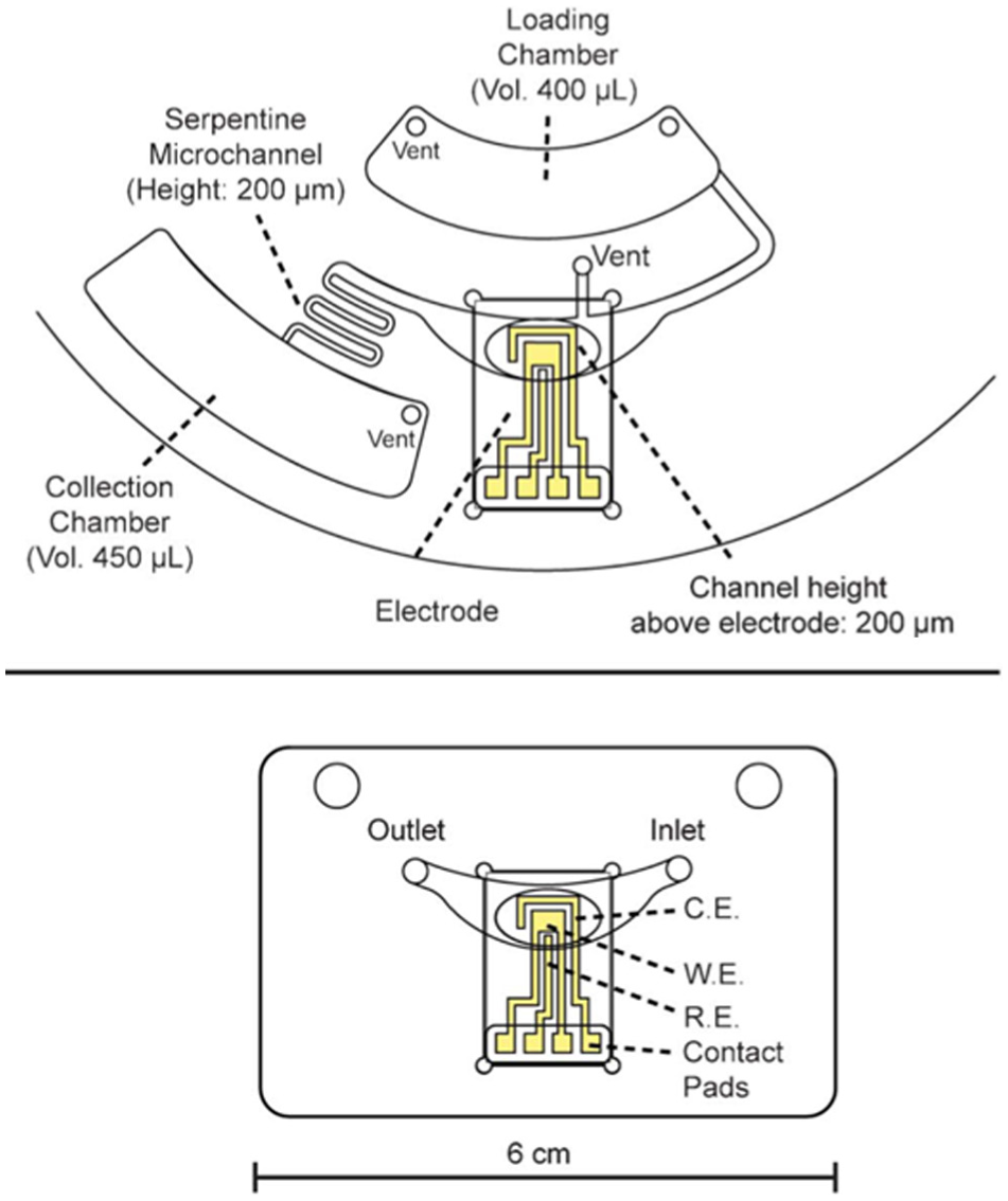
Abi-Samra et al. developed a flow velocimetry device by integrating an electrode array onto a centrifugal microfluidic platform. (
Nwankire et al. developed an electrochemical LoD platform that performed whole blood fractionation and label-free detection of SKOV3 cells from whole blood. 158 They achieved a detection limit of 214±5 captured cells/mm2 and a capture efficiency of 87%.
Future Outlook for Analyte Detection Strategies
Although colorimetric detection for molecular diagnostics has not yet been implemented on a centrifugal microfluidic platform, several techniques developed by molecular biology groups can be integrated on a disc in the near future.159–162 These colorimetric detection schemes can reduce hardware complexity when thermocycling is required and cut the cost of reagents compared to fluorescent detection schemes. However, streamlining and automation of multiple steps to achieve colorimetric detection will be required.
Other future work in analyte detection on a CD may involve integration of more compact and user-friendly optical methods and enhancing their lower limit of detection in applications such as early disease diagnosis and measurement of minute concentrations of biological toxins in wastewater. The move toward the use of inexpensive and modular CD and DVD drives for optical detection is another future goal. 164 However, despite advancements in optical hardware, we believe that the move toward electrochemical detection, which is less costly and more compact, is inevitable. In addition, optical detection requires complicated image analysis, which is generally difficult to automate and can be slow. With advances in microelectrode arrays, electrochemical detection can be integrated easily into microfluidic discs and provides fast analysis.
The future integration of electrochemical detection on a CD, which has already been successfully achieved via both an electrical slip ring (see the slip ring in Fig. 7D ) and induction, provides several advantages. Replacement of optical detection schemes allows for cheaper, biocompatible materials to be used instead of the expensive, optically clear substrates required for imaging. Smaller electrodes can be produced for a smaller footprint on the disc, leaving space for other features.
Furthermore, electrochemical DNA biosensors pose an attractive alternative to DNA microarrays and other optical DNA detection methods.165–167 The most common electrochemical biosensors detect DNA hybridization by labeling the target DNA with a tag such as ferrocene, a redox-active enzyme,167–170 or redox-active silver or gold nanoparticles.171,172 Azek et al. demonstrated the sensitivity of this technique with their enzyme label–based biosensor. 173 The group used a peroxidase enzyme label and a screen-printed carbon electrode to detect DNA sequences in human Cytomegalovirus. The limit of detection of the target was 0.6 amol/mL, making the technique 83 times more sensitive than standard hybridization techniques using colorimetric methods.
Due to the redox-active nature of certain DNA nucleotides, label-free electrochemical detection methods have also been successfully developed.174,175 Palecˇ ek et al. showed that both DNA and RNA produce reduction and oxidation signals following hybridization. 176 Because guanine is the most redox-active DNA nucleotide, successful label-free electrochemical DNA hybridization sensors have immobilized guanine-free DNA probes for target detection. Chen et al. created an ultrasensitive label-free electrochemical DNA biosensor by using self-assembled DNA nanostructures for signal amplification. 177 The limit of detection was measured as 2 amol/mL of target, making this sensor more sensitive than any optical technique.
Although these electrochemical DNA biosensors have not yet been integrated in CD microfluidics, they present a cost-effective yet highly sensitive alternative to optical detection methods, particularly in the burgeoning field of molecular diagnostics.
Conclusion
This review has highlighted the technologies needed to develop fully integrated molecular diagnostic LoD systems not yet available in the commercial market. Table 3 summarizes the array of enabling techniques on CDs discussed in this review, their applications, and the specific advantages these techniques have when used on microfluidic discs.
Summary of Fluidic Operations and Reagent Storage Techniques Executed on Centrifugal Fluidic Platforms.
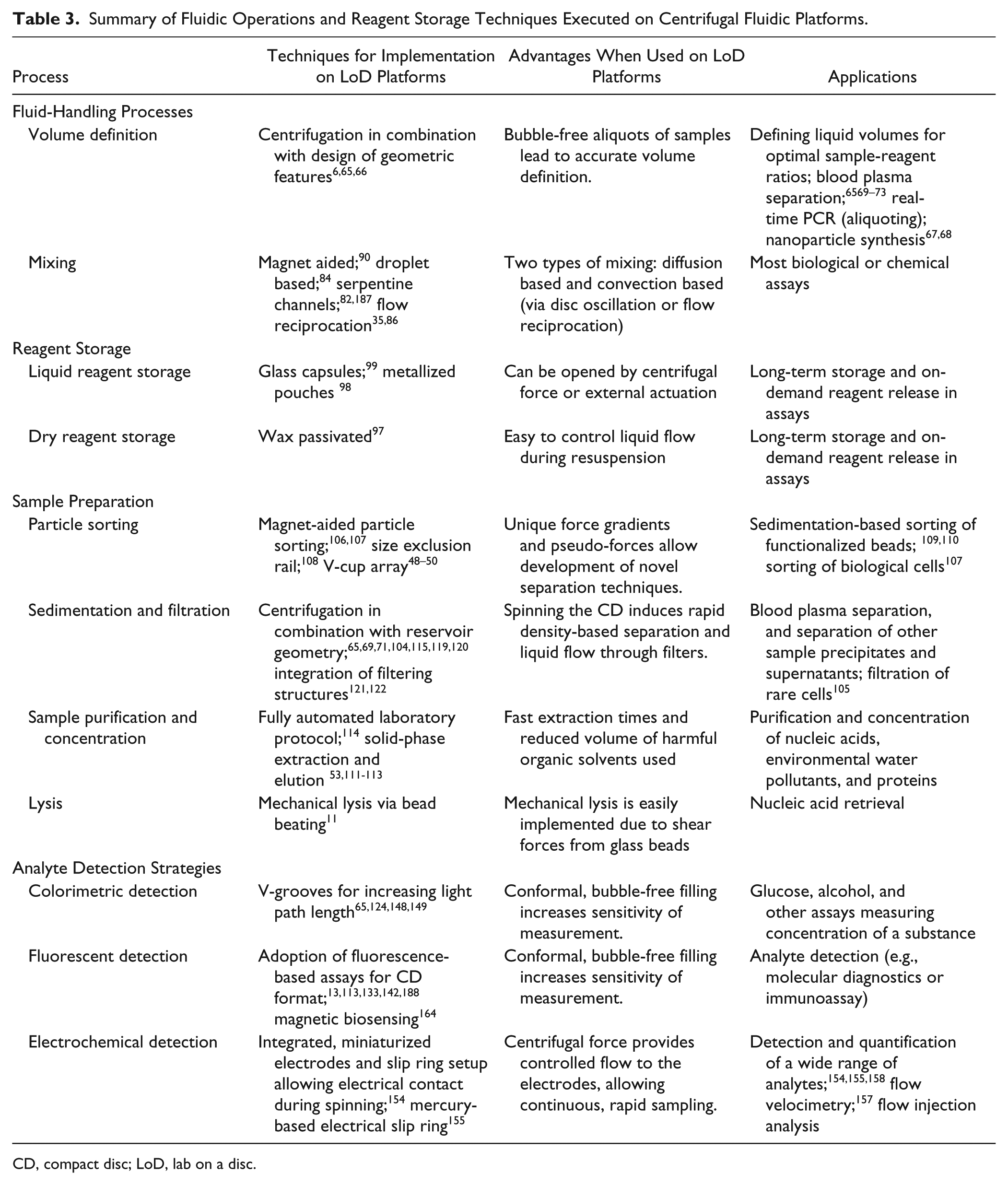
CD, compact disc; LoD, lab on a disc.
There are several commercial microfluidic molecular diagnostic systems currently available on the market, including the Cepheid GeneXpert®, the cobas® Liat system by Roche Molecular Systems Inc., BioFire Diagnostics’s FilmArray®, and the Alere(TM) i. However, the only commercially available molecular diagnostic LoD system is Focus Diagnostic’s Simplexa(TM) system, which utilizes RT-PCR to amplify, detect, and differentiate between human influenza A, human influenza B, and RSV RNA. Even this system is not ideal, requiring off-disc storage of reagents at specific temperatures and manual transfer of reagents before running the test. The complexity involved in sample-to-answer molecular diagnostic assays has prevented the development of more commercial products. To date, the most successful commercial LoD systems developed have included blood chemistry analysis, blood plasma separation, and water quality analysis.178–183 These systems have been developed to perform a limited number of fluidic steps and therefore lack some crucial functionalities. The transition toward total analysis molecular diagnostic LoD systems not only requires more sophisticated fluid-handling techniques and complex hardware, but opens up the way for fully self-contained point-of-care systems. For example, many point-of-care systems are required to operate with low power consumption while maintaining an environment with specified temperature and humidity regardless of their external conditions. Therefore, LoD systems need to incorporate temperature- and humidity-controlled environmental chambers, alternative power sources such as solar panels or fuel cells, and storage capsules for vapor-tight storage of both liquid and dry reagents.
Furthermore, LoD systems need to integrate multiple-step assays while being both portable and user-friendly (ideally waived under the Clinical Laboratory Improvement Amendments criteria). For example, GenePOC Diagnostics developed a sample-to-answer LoD system for nucleic acid detection that integrates lysis, volume definition, PCR, and reagent storage on a single disc that can obtain results within 1 h.100,179
This review also emphasizes the need for modular hardware elements to simplify the design of LoD systems. One example of a multifunctional setup includes the use of thermoelectric elements for heating, cooling, as well as reversible valving. 16 Yet another example is the LabTube, which is not a microfluidic disc but uses a traditional programmable centrifuge to execute fluidic operations within a specifically designed centrifuge tube, reducing the cost of hardware development and production. 184 Hardware modularity, combined with strategic on-disc operations, will increase the portability and reduce the cost of the overall system, making it more amenable to commercial applications.
Besides its role as a commercial sample-to-answer system, the LoD platform can be used for research in remote locations, such as in the International Space Station or research bases in Antarctica. More than a decade ago, NASA studied the potential of using on-site 3D printed microfluidic discs for both diagnostics and experimental studies in a microgravity space environment. 185
To manufacture integrated sample-to-answer LoD systems in low-resource environments, self-contained and flexible advanced manufacturing platforms, called desktop integrated manufacturing platforms (DIMPs), are especially useful. DIMPs represent the factory of the future, consisting of compact, inexpensive, and easy-to-operate rapid prototyping subplatforms that enable the manufacturing of all aspects of a complete diagnostic device. 186 For LoD systems, these subplatforms can include manufacturing of reagent storage capsules, building of optical detection setups, and injection molding of all fluidic features. 24 DIMP technologies can replace traditional centralized manufacturing facilities to provide on-site solutions in developing countries, war zones, and extreme environments. Given the CD platform’s capability for providing complete and automated sample-to-answer solutions, it is an even more powerful research and diagnostic tool when combined with the manufacturing flexibility of DIMPs.
There remain many more areas in which centrifugal microfluidics will find new and exciting applications, both as a research tool and in the point-of-care market. We envision that the LoD platforms of the future will be self-contained environments that incorporate modular hardware components and effective storage solutions, capable of performing complex sample-to-answer assays in a variety of settings.
Footnotes
Acknowledgements
The authors would like to thank Genome Quebec and the National Institute of Health for funding this publication (Grant 1 R01 AI089541-01).
Declaration of Conflicting Interests
The authors declared no potential conflicts of interest with respect to the research, authorship, and/or publication of this article.
Funding
The authors disclosed receipt of the following financial support for the research, authorship, and/or publication of this article: The authors would like to thank Genome Quebec and the National Institute of Health for funding this publication (Grant 1 R01 AI089541-01).
References
Supplementary Material
Please find the following supplemental material available below.
For Open Access articles published under a Creative Commons License, all supplemental material carries the same license as the article it is associated with.
For non-Open Access articles published, all supplemental material carries a non-exclusive license, and permission requests for re-use of supplemental material or any part of supplemental material shall be sent directly to the copyright owner as specified in the copyright notice associated with the article.