
Abstract
Label-free measurements of the reaction kinetics of a small sample volume are essential for efficient drug discovery, requiring methods and systems that are rapid, accurate, and cost-effective. Herein, we present an integrated optofluidic system for label-free characterization of reactions in a nanoliter reagent volume. This system contains a droplet-based microfluidic sampling section and an optical fiber–based spectroscopy detection section. By manipulating droplets containing reagents at certain concentrations at different times, quantifiable measurements via absorption spectroscopy can be made in a simple, sensitive, and high-throughput manner. We have demonstrated our system’s capability by performing potency (IC50) assays of an inhibitor in a TEM-1 β-lactamase (enzyme) and nitrocefin (substrate) system. This integrated platform can potentially provide an automated, label-free, and low-cost method for many other assays of reaction kinetics.
Keywords
Introduction
Label-free measurements of reaction kinetics in a tiny volume are of great importance in many chemical, biochemical, pharmacological, and biomedical fields.1–4 Especially in the drug discovery industry, screening new drug candidates usually relies on the characterization of numerous chemical, DNA, and protein interactions.5–10 Once the target candidate has been identified, a toxicity test matrix of hundreds of different parameters is also required to identify different conditions that increase the affinity, selectivity, potency, and stability.5,11,12 In addition, the ability to monitor drug concentration in clinical blood samples is needed to reveal the drug metabolism rate. To improve this process, developing better analytical systems has been an ongoing challenge. Minute volumes of reagents or samples need to be processed without loss or contamination. After which, the reaction or interactions should be characterized in a simple, real-time, and label-free method with a high-performance detection unit.
Over the past decades, great advances have been made in both aspects. For sample processing, droplet-based microfluidics13,14 has been demonstrated to effectively handle tiny volumes of liquids. By dispersing an aqueous reagent solution into an oil phase, aqueous-in-oil droplets can be produced with volumes ranging from femtoliters to nanoliters,13–15 which is much smaller than the sample volume in traditional assays. In addition, by isolating each individual droplet in an immiscible oil phase, sample dilution and cross-contamination can be minimized or avoided.16–18 High-throughput screening is another advantage of droplet-based microfluidics.19–24 Droplet-based microfluidics enables rapid and stable production and precise control (including size, components, and concentration) of droplets. In addition, various means of droplet handling, such as transport, fusion, mixing, and sorting,14,16,17,25–33 make it convenient to create a droplet library with diverse compositions inside and to analyze them in a high-throughput manner.
Furthermore, measuring the absorbance spectrum provides an excellent, real-time, label-free detection method.34–36 Compared with other detection mechanisms, it has several distinct advantages. First, it totally requires no external chemical labels, which avoids nonspecific labeling, chemical activity loss in the substrate, laborious staining work, and the consumption of biochemicals with fluorophores. Furthermore, the absorbance spectrum can reflect the inherent chemical feature of the analyte. The peak locations and intensity of the absorbance spectrums are defined by the absorbance of chromophores in the UV-visible region. 37 These chromophores, such as carbon-carbon double bonds (C=C), carbon-carbon triple bonds (C≡C), carbon-oxygen double bonds (C=O), nitrogen-oxygen double bonds (N=O), and aromatic rings, are natural structures in many organic molecules. Once the chromophores have been changed because of a reaction, the absorption peaks will shift, and this is a direct proof of a chemical reaction occurring.
Despite the advances in droplet microfluidics and the measurement of the absorbance spectrum, these methods have not been integrated in an optimum manner in a lab-on-a-chip system to investigate reaction kinetics. Absorption spectroscopy was usually performed in a microfluidic system using an objective lens. 38 This setup requires multiple optical elements such as a light source to excite the spectrum signal in the analyte, an inverted microscope to focus the emitted light, and a high-frame-rate CCD camera to capture the signal. The equipment (e.g., the microscope and the fast CCD camera) is expensive, which creates a high entry barrier to the use of this technique.
Herein, we have developed an integrated device that combines a droplet-based microfluidic sampling section with an on-chip, optical fiber–based spectroscopy unit for absorbance spectrum measurement. In our device, the laser excitation and emission detection components are coupled into two optical fibers embedded orthogonally to the longitudinal axis of the microfluidic channel. This eliminates the need for an active alignment system, an expensive CCD camera, and a fluorescent microscope. Such an integrated device and associated protocol enables a practical, portable, cost-effective, automated tool for biochemical analysis. Here we demonstrated the capability of our optofluidic39–46 (i.e., fusion of optics and microfluidics) device to investigate reaction kinetics by performing label-free measurements of enzyme kinetics and an inhibitor potency (IC50) assay. In our experiments, the substrate, the enzyme, and the inhibitor were mixed and delivered through a droplet microfluidic device. The reaction time was controlled by the length of the microchannel and the fluid injection flow rate. A fiber-based absorbance detector was embedded near the end of the microfluidic channel to measure the absorbance spectrum. The shift in the absorption peaks from the substrate to the product was monitored in real time to evaluate the performance of the enzyme inhibitor. Our design keeps all the advantages of both droplet-based microfluidics, such as screening of multiple conditions simultaneously, while performing sophisticated fluidic operations, and the label-free, real-time properties from the use of absorbance-based detection. Moreover, this integrated fiber-based system offers advantages by not requiring a microscope, which enables portability as an analytical lab-on-a-chip system. In the future, this simple but effective device could become a valuable tool for accurate biocatalysis studies, rapid clinical diagnosis, and low-cost drug discovery.
Experimental Methods
Chip Design
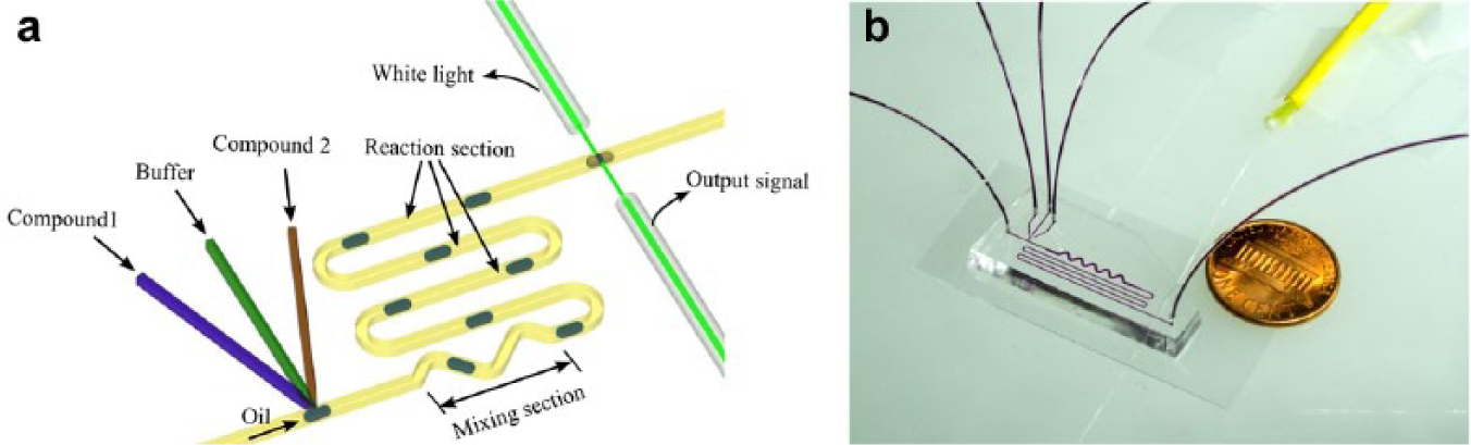
An illustration of the droplet-based optofluidic device is shown in Figure 1 . This device consists of three sections necessary for measurements of reaction kinetics: a droplet generation section, a mixing and reaction section, and an optical fiber–based absorbance detection section. In the droplet-generation section, the compound 1 solution (the substrate solution), the compound 2 solution (the enzyme or enzyme-inhibitor mixture solution), and the buffer solution are injected into the microfluidic channel from the three respective inlets. They are dispersed into a continuous oil flow to generate solutions-in-oil droplets. In the mixing section, the droplets are well mixed due to intradroplet flow circulation and are allowed to react along the long, serpentine-shaped channel. Finally, the absorbance spectrum of the droplet after the reaction is detected in real time by the absorbance detection section. The reaction kinetics can be calculated based on the absorbance measurements of the droplets.
(
Device Fabrication
A polydimethylsiloxane (PDMS) layer patterned with the channel and inlets was fabricated using a standard, two-step soft-lithography and mold-replica technique. 24 The channel height is 125 µm, the channel width of the mixing section is 400 µm, and the width of the remaining channels is 200 µm. The channel length of the mixing section is 16 mm, and the length of the remainder is 92 mm. After plasma oxidation of the interfaces, the PDMS layer was sealed to a glass slide to form the microfluidic device.
Optical Setup
The absorbance detection section contained two optical fibers (Thorlabs, Newton, New Jersey, USA AFS105.125Y, multimode, core diameter 105 µm, cladding diameter 125 µm, NA = 0.22), a visible white light source (LS-1 tungsten halogen lamp; Ocean Optics, West Hartland, Connecticut, USA), a high-resolution spectrophotometer (HR4000CG-UV-NIR; Ocean Optics), and a computer for data acquisition. The optical fibers were positioned and automatically aligned by two guide chambers fabricated47,48 in the PDMS layer with a height of 125 µm and a width of 125 µm. The input fiber (shown in Fig. 1 ) illuminated the droplet with white light. The transmitted light was then collected by the output fiber, which was connected to a high-resolution spectrophotometer. A computer determined the resulting absorbance spectrum from the spectrophotometer via a software program (SpectraSuite; Ocean Optics). The absorbance can be indicated as a logarithmic ratio between the intensity of the input light and the output light. It is expressed as A = –log10(Iin /Iout), where Iin and Iout are the intensities of the input light and the light after traveling through the droplet, respectively. In our experiments, the light transmitted through the main oil flow was measured and used as the reference input light intensity Iin. Iout was recorded by the spectrophotometer as the droplets passed through the detection region.
Chemicals and Reagents
Rhodamine 6G (R6G; Sigma-Aldrich, St. Louis, MO) was dissolved using deionized (DI) water to form a series of R6G solutions with concentrations from 0.1 to 1.0 mM. The enzyme, TEM-1 β-lactamase from Escherichia coli (Life Technologies, Carlsbad, CA), was used in the experiment to hydrolyze the substrate. It was stored in an enzyme storage solution containing 10 µg/mL enzyme, 200 mM potassium phosphate (pH 7.0), and 50% (v/v) glycerol at −20 °C. Nitrocefin (Toku-E, Bellingham, WA) was used as the substrate in the enzymatic reaction. It was stored in DMSO at −20 °C at a concentration of 20 mM as the substrate storage solution. Potassium clavulanate was used as the inhibitor in the enzymatic reaction. It was dissolved in DI water to form the inhibitor solutions, with concentrations ranging from 10 nM to 1 mM. The primary buffer solution contained 100 mM sodium phosphate and 0.1% bovine serum albumin (BSA) (w/w) at pH 7.0. Mineral oil, mixed with 1.5% Span 80 (w/w), was used as the oil phase to generate the droplets.
Before the experiments, the aforementioned storage solutions were mixed with the primary buffer and DI water to form the final solution for sample injection. The final substrate solution was formed by mixing 10 µL substrate storage solution, 50 µL primary buffer solution, and 40 µL DI water. This final substrate solution contained 2 mM nitrocefin, 50 mM sodium phosphate, and 0.05% BSA (w/w). The final buffer solution was obtained by diluting the primary buffer solution to a final concentration of 50 mM with DI water. The final enzyme solution was formed by mixing 5 µL enzyme storage solution, 50 µL primary buffer solution, and 45 µL DI water. The resulting final enzyme solution contained 0.5 µg/mL TEM-1 β-lactamase, 50 mM sodium phosphate, and 0.05% (w/w) BSA. The inhibited enzyme solution, which was used for the inhibitor potency measurement experiments, was a mixture of 50 µL primary buffer solution, 5 µL enzyme storage solution, 10 µL inhibitor solution (with concentrations varying from 10 nM to 1 mM), and 35 µL DI water. The inhibited enzyme solution was stored at 20 °C for 30 min before being injected into the device, allowing the inhibitor to fully react with the enzyme. All the enzymatic reactions were conducted at 20 °C. Before the experiments, all the channels were flushed with the buffer solution to coat the channel walls and prevent enzyme absorption by the PDMS.
Results and Discussion
Calibration of the Absorbance Detector
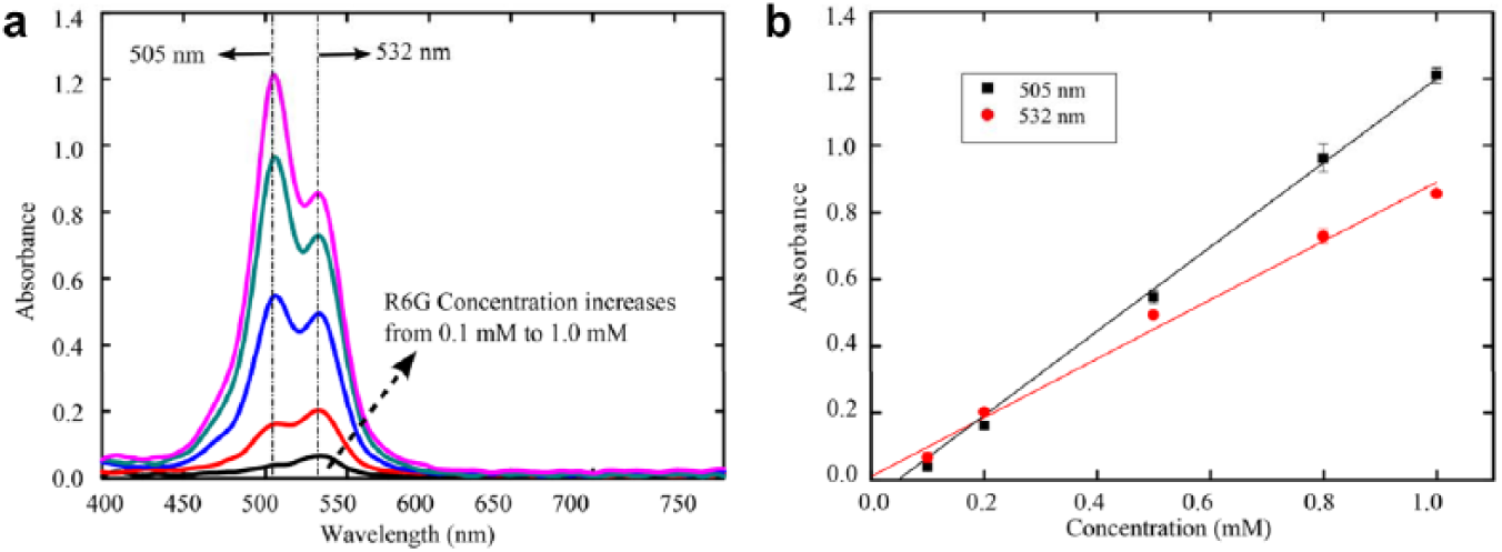
To quantitatively measure the contents of a droplet by our platform, we first calibrated the absorbance detector by measuring the absorbance spectrums of droplets containing R6G solutions at different known concentrations. In each test, R6G aqueous solutions at the same concentration were injected into all three inlets. The flow rate of each of the three inlets was 0.4 µL/min. The flow rate of the mineral oil flow was 0.6 µL/min.
The absorbance spectrums of the R6G aqueous solutions with concentrations of 0.1 mM, 0.2 mM, 0.5 mM, 0.8 mM, and 1.0 mM were measured. Figure 2a plots the absorbance spectrum curves. Figure 2b gives the absorbance values for the R6G solutions at different concentrations with absorbance peaks at wavelengths of 505 nm and 532 nm. The absorbance spectrums from hundreds of droplets were measured in each test. Each data point in Figure 2b was obtained by averaging the peak absorbance values at each solution concentration. Two error-weighted regressions were conducted to characterize the linearity of the absorbance values at different concentrations. The R2 values for the two error-weighted regressions were 0.994 at 505 nm and 0.987 at 532 nm. These results show a good linear response and fit in absorbance amplitude with respect to changes in concentration. This indicates that our method is capable of quantitatively analyzing the concentrations of the contents in the droplets.
Quantification of R6G at different concentrations via differences in its absorbance spectrums. (
Characterization of Absorbance Shift
After the calibration, the device was applied to monitor the enzymatic reaction from substrate to product by measuring the change in the absorbance spectrum of the droplet. Since the reaction in each droplet is detected only once, it is necessary for the absorbance spectrum to measure both the concentrations of the reagents and the products. Since the reagent and the product have an absorbance maximum at different wavelengths, the absorbance spectrum of a droplet can indicate the concentrations associated with both the reaction extent and the reaction rate.
Here, an enzymatic reaction was chosen with TEM-1 β-lactamase (enzyme) and nitrocefin (substrate) reaction compounds. In this reaction, there is a significant difference in the absorbance signals between the substrate and the product, which is desirable for absorbance detection. The absorbance spectrum of the substrate without hydrolysis was tested first. The substrate solution at a concentration of 500 µM was injected into all three inlets at a flow rate of 0.4 µL/min for each inlet. The flow rate of the mineral oil was 0.6 µL/min.
In addition, the absorbance spectrum of the hydrolyzed product was measured. The product solution was obtained using the following procedure. Before the test, 5 µL of the enzyme solution (10 µg/mL) and 10 µL of the substrate solution (20 mM) were added into 50 µL of the primary buffer solution (pH 7.0). Then, DI water was added to make a final solution with a volume of 100 µL. After reacting for 30 min at room temperature, the enzyme-substrate solution was injected into the device. For this test, the compound 1 inlet was a buffer solution, and the enzyme-substrate mixture was injected into the compound 2 inlet. The flow ratio of the compound 1, buffer solution, and the mixture solution was 1:2:1. The final concentrations of the reagents in the droplet were 0.125 µg/mL of enzyme and 500 µM of substrate.
The absorbance spectrums of the substrate (before reaction) and the product (after reaction) are shown in Figure 3 . It clearly shows that there is an absorbance peak shift between the absorbance spectrums of the substrate and the product. The absorbance peak of the substrate was lower than 400 nm (which is outside of the range of the white light source’s spectrum), while the product peak was around 486 nm. The shift in the absorbance peaks matched the results reported by Wang et al. 49 and Lisa et al. 50 They state that the absorbance peak for nitrocefin is at 390 nm, and the peak for the product is around 486 nm. Our results demonstrated that this enzymatic reaction can be detected by our device based on the shift in the absorbance signal. Furthermore, these absorbance spectrums will act as references for determining the potency of the inhibitor in the following experiments.
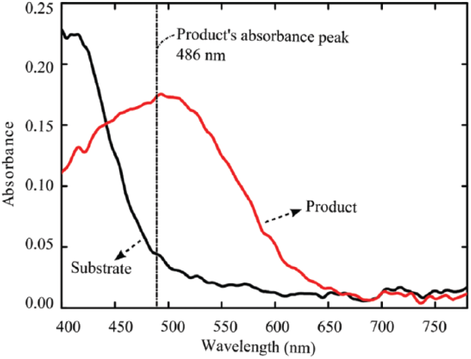
The absorbance spectrums used to identify both the reagent and product of the reaction. The black and red curves represent the absorbance spectrum of substrate (nitrocefin, 500 µM) and the hydrolyzed product in our enzymatic reaction, respectively.
Determination of Reaction Times
The reaction time is a critical parameter for all the chemical reactions. By controlling the reaction time and quantifying the substrates and products, the reaction kinetics can be determined. In our platform, the reaction kinetics was precisely monitored by varying the droplet transport speed. Here, the reaction time can be defined by the time interval between when the reagents inside the droplet were well mixed and when the droplet passed through the detection region. For the enzymatic reaction used in our experiments, the reaction time was simplified and defined as the time that it took a droplet to be transported from the droplet generation point to the absorbance detection region since the reaction time (tens to hundreds of seconds) is much longer than the time it took for the reagents to mix (evaluated as 0.1–0.3 s in our experiments by the method of Bringer et al. 51 ) as the droplet flowed through the serpentine-shaped channel. By controlling the droplet flow rate, we quantified the hydrolyzed product in the droplets at different time points and could find a suitable reaction time period where even the enzyme without inhibition cannot completely hydrolyze the substrate.
In our experiments, the substrate, buffer, and enzyme solutions were injected into one of the three respective inlets, as illustrated in Figure 1 . All the injected solutions were the final solutions detailed in the “Chemicals and Reagents” section. The flow rate ratio of the substrate solution, the buffer solution, and the enzyme solution was fixed at 1:2:1, in order to fix the final concentrations of the reagents in the droplets for all the tests. The concentrations of the substrate and enzyme in each droplet were 500 µM and 0.125 µg/mL, respectively.
The absorbance spectrums of droplets at different reaction times (via control of the flow rate) are shown in Figure 4a . The absorbance value around a wavelength of 486 nm increased with increasing reaction times, while the value near 400 nm decreased. This trend indicates that more substrate was being hydrolyzed into the product as the reaction progressed. The absorbance values of the droplets at 486 nm in each absorbance spectrum can be used to characterize the progress of the enzyme reaction. Figure 4b shows the absorbance value of the droplets at 486 nm for different reaction times. This illustrates that the enzyme (with no inhibitor) solution at this concentration needed about 2 min to hydrolyze all the substrate in a droplet. Thus, in this situation, the maximum reaction time for inhibitor potency measurements should be less than 2 min. To further ensure that the substrate would not be completely hydrolyzed in each droplet before reaching the detection section, we chose a relatively short reaction time of 47 s for the inhibitor potency measurements, as described in the following section. The flow rates for oil, substrate, buffer, and enzyme solutions were set at 0.8, 0.8, 1.6, and 0.8 µL/min, respectively. The size of the droplets generated under this condition was 22.08 ± 1.84 pL.
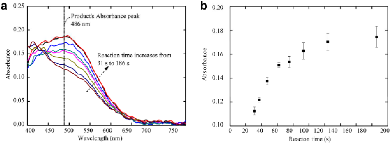
Absorbance spectrums of the reagent or product at specific reaction times. (
Measurement of Inhibitor Potency
An inhibitor, a molecule that significantly changes the reaction kinetics, is widely used in drugs and biocatalysis reagents. This platform was applied to measure the inhibitor potency parameter IC50 as a potential replacement for a conventional reaction inhibitor potency assay that consumes larger quantities of reagents and time and relies on parallel reactions. In our experiments, the absorbance spectrums of the droplets containing the substrate and enzyme-inhibitor compound solutions, with different inhibitor concentrations, were tested at a fixed reaction time (47 s). The potency parameter of the inhibitor, IC50, was calculated from the detected absorbance spectrums. This experimental protocol followed the method detailed in the “Determination of Reaction Times” section. The only difference was that the enzyme solution was replaced by an enzyme-inhibitor mixture. Enzymatic activity after reacting with the inhibitor at seven different concentrations (1.0, 10, and 100 nM and 1.0, 10, 50, and 100 µM) were determined. Before each test, the enzyme-inhibitor mixtures were prepared using protocols mentioned in the “Chemicals and Reagents” section. Afterward, the mixture was injected into one inlet and was encapsulated into oil droplets with the substrate solution and the buffer solution prior to absorbance detection. It should be noted that the concentrations of the inhibitor ranged from 1.0 nM to 100.0 µM in the test tubes and were diluted to a range from 0.25 nM to 25 µM in the droplets because the flow ratio of the substrate solution, the buffer solution, and the enzyme-inhibitor mixture was 1:2:1.
The absorbance spectrums of the droplets with different levels of enzyme inhibition are shown in Figure 5a . As the concentration of the inhibitor increases, the absorbance value at 486 nm decreases and the value near 400 nm increases. This change indicates that the higher the concentration of the inhibitor, the less the substrate would be hydrolyzed. The activity of the enzyme after reacting with different concentrations of inhibitor is determined from the measured absorbance spectrums. In the previous section ( Fig. 3 ), it was demonstrated that the absorbance spectrums of the substrate and the hydrolyzed product both had an absorbance at 486 nm but with different values. We assume that the absorbance spectrum of a droplet is a combination of the absorbance spectrums of the substrate and the hydrolyzed product in a droplet. As a result, the absorbance value (A) at 486 nm of an absorbance spectrum can be expressed as
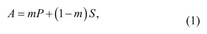
where S and P are the absorbance values of the substrate and the product, respectively; m is the percentage of the substrate hydrolyzed by the enzyme in a droplet. The values S and P can be obtained from Figure 3 . From equation (1), the percentage of the substrate hydrolyzed by an enzyme without inhibition, or an inhibited enzyme at the seven different inhibitor levels, can be calculated. The percentage of hydrolyzed substrate by only the enzyme is denoted as m0, and then the corresponding percentages for the inhibited enzymes are denoted as mi (where i = 1–7). The activity of the enzyme inhibited at different levels can now be quantified by the ratio of mi/m0. The activity of the enzyme without any inhibitor is defined as 100%.
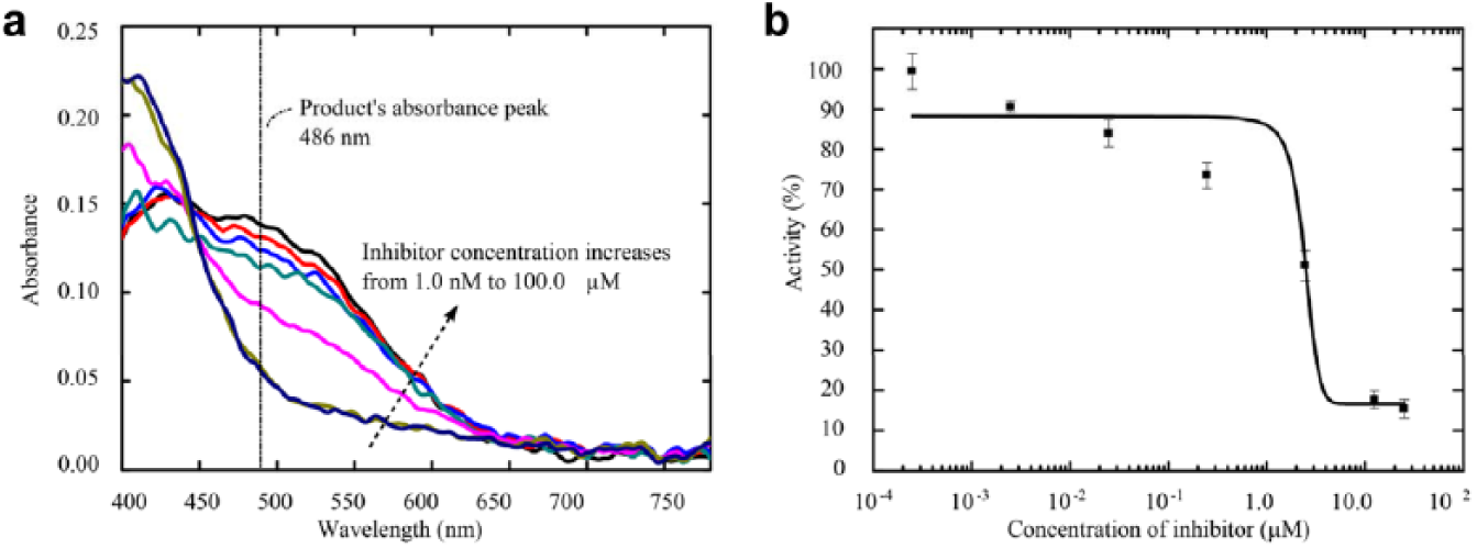
Absorbance spectrums of droplets containing the enzyme, substrate, and inhibitor at different concentrations. (
The activity curve of the enzyme at different inhibition levels is shown in Figure 5b . It is clear that the higher the activity of the enzyme, more of the substrate would be hydrolyzed for a given reaction time. The results were fitted as a function of the activity values versus the concentrations of inhibitor in the droplets. The fitting method is a sigmoidal dose-response variable slope, and the R2 is 0.9658. The IC50 value of the inhibitor was calculated to be 2.5 µM under our experimental conditions.
It needs to be highlighted that our device, with properties of being high throughput, microscope free, label free, and low cost, is especially suitable for IC50 measurement. This is because the IC50 value depends on concentrations of the enzyme, the inhibitor, and the substrate along with other experimental conditions. 52 Therefore, measurement of IC50 is not the same as measurement of other intrinsic, thermodynamic quantities (e.g., rate constant). In the latter case, once the parameter is characterized, it can be readily searched from an available database and compared between experiments. On the contrary, IC50 value has to be routinely measured when laboratory experimental conditions change, even though the enzyme, substrate, and inhibitor are the same material. From this perspective, conventional IC50 assays are not suitable due to the complexity of instruments and significance of reagent consumption. A conventional IC50 test requires 96-well assays, microscopy, and a UV-Vis spectrometer to monitor the reaction extent; ~10 mL reagent is consumed (~100 µL for a single experiment, with nearly 100 parallel experiments required). On the other hand, our demonstrated device completely avoids using any of aforementioned instruments, while enabling precise control of the reaction time and substrate/enzyme/inhibitor concentration and label-free detection of the reaction extent. The reagent consumption was significantly reduced as well (picoliter volume in each droplet). Due to the advantages of this technique, it could be widely used in a large-scale reaction kinetic assay; more importantly, it could be conducted outside of the few specialized biological laboratories that are currently equipped to perform these measurements.
In summary, an optofluidic device with an integrated droplet-based sample handling unit and an absorbance spectrum detection section was developed for label-free monitoring of reaction kinetics with a sub-nanoliter sample volume. It has advantages of both droplet-based microfluidic devices (such as low reagent consumption, high throughput, and easy generation of large diverse compound libraries) and absorbance spectrum measurements (i.e., label-free, simple, low-cost detection). The capabilities of this device were initially demonstrated by detecting the absorbance spectrums of droplets containing different concentrations of R6G aqueous solutions. The device was then employed to characterize the enzymatic reaction kinetics and the potency of an inhibitor (potassium clavulanate) on the enzyme TEM-1 β-lactamase. The potency parameter IC50 of the inhibitor was determined to be 2.5 µM for our experimental parameters. This enzyme inhibition study demonstrated that our device is capable of measuring the potency of inhibitors and for performing enzyme assays in a simple and efficient manner. With its aforementioned advantages, this platform could be widely used in many pharmacology and biochemistry applications.
Footnotes
Acknowledgements
We thank Dr. Peter Hu, Dr. Danqi Chen, and Dr. Yijun Deng for their helpful discussions.
Declaration of Conflicting Interests
The authors declared no potential conflicts of interest with respect to the research, authorship, and/or publication of this article.
Funding
The authors disclosed receipt of the following financial support for the research, authorship, and/or publication of this article: We gratefully acknowledge financial support from the National Institutes of Health (Director’s New Innovator Award, 1DP2OD007209-01), the National Science Foundation, the Penn State Materials Research Institute, and the Penn State Center for Nanoscale Science (MRSEC) under grant DMR-0820404. Components of this work were conducted at the Penn State node of the NSF-funded National Nanotechnology Infrastructure Network.
References
Supplementary Material
Please find the following supplemental material available below.
For Open Access articles published under a Creative Commons License, all supplemental material carries the same license as the article it is associated with.
For non-Open Access articles published, all supplemental material carries a non-exclusive license, and permission requests for re-use of supplemental material or any part of supplemental material shall be sent directly to the copyright owner as specified in the copyright notice associated with the article.