
Abstract
Electrospun nanofibers have been developed into a variety of forms for tissue engineering scaffolds to regulate the cellular functions guided by nanotopographical cues. Here, we have successfully fabricated nanofiber-based scaffold complexes of rod and sheet type by combining the three microfabrication techniques of electrospinning, spin coating, and polymer melt deposition. It was demonstrated that this hybrid fabrication could produce uniaxially aligned nanofiber scaffolds supported by a thin film, allowing for a mechanically enforced substrate for cell culture as well as facile scaffold manipulation. The results of cell analysis indicated that nanofibers on spin-coated films could provide contact guidance effects on cells and retain them even after manipulation. As an application of the cell-laden nanofiber film, we built a rod-type structure by rolling up the film around a mechanically supporting core microfiber, which was incorporated by polymer melt deposition. A biocompatible and biodegradable polymer, polycaprolactone, was used throughout the processes and thus could be used as a directly implantable substitute in tissue regeneration.
Introduction
One of the important issues in the tissue engineering field is to provide cultured cells with a biocompatible template, or scaffold, which mimics the natural extracellular matrix (ECM), to regulate cell functions, such as adhesion, migration, proliferation, and differentiation.1–3 Through the scaffold-based strategies, a wide range of research has been conducted to understand the cellular processes controlled by the surrounding microstructure as well as to develop scaffolds for practical applications in clinical settings.4–6 Among many micro- and nanoprocessing tools for the scaffold fabrication, the electrospinning process has offered unique advantages due to its ability to produce nanofiber networks that closely simulate the ECM structure, which is a complex network with various nanoscale fibrils such as collagen, elastin, fibronectin, and laminin.7–10 The ECM mimicry is beneficial for cell activation and characterized by high productivity, simplicity, and material universality in manufacturing the nanofibers.
Because the electrospinning process is driven by strong electrostatic force from high voltage, the as-spun fibers usually form a randomly configured nonwoven matrix. Recently, the nanofiber patterning technique has been diversified by modulating its configuration from simple random networks to a uniaxially aligned form, which in turn can generate desired cell morphogenesis. The feasibility of aligned nanofiber scaffolds has been demonstrated using various cells such as fibroblasts, myoblasts, neuron cells, and mesenchymal stem cells.11–17 Especially in the case of myoblasts, their native tissue, skeletal muscle, has a highly organized anatomical structure that consists of many parallel bundles formed by fusion of the myoblasts. It naturally follows that the ordered nanofiber scaffolds are necessary to mimic the native muscle architectures. To achieve the ordered fiber configuration, a variety of methods have been proposed by developing specific collecting mechanisms such as a rotating cylinder, a sharp-edged disk, a wire-framed drum, a near-field working distance, and parallel electrodes.18–22
We previously reported a novel processing technique to acquire the ordered nanofiber array scaffold not only with better alignment but also with quantitatively controlled fiber density. 23 The multiple transfers of nanofibers, by which the nanotopographic spacing could be modulated, were a favorable feature to demonstrate the contact guidance effect of the nanofiber pattern. In particular, the well-aligned nanofiber pattern with the controlled configuration showed improved biological functions in cellular adhesion and morphogenesis. 24 However, the previous nanofiber manufacturing methods need to be assisted by some postprocessing procedures, allowing for facile manipulation of the produced nanofibers. While the random mesh has a number of overlapping junctions on the constituent nanofibers, the structural interconnections in the aligned mesh are not abundant so that it cannot be handled as an individual entity. The sparse connectivity between aligned nanofibers implies that a supportive structure should be incorporated to prevent a possible distraction of nanofibers.
Here, we introduce an effective hybrid fabrication method to build a new kind of rod- or sheet-type composite scaffold that consists of a spin-coated polymer film and an array of electrospun nanofibers. A series of polycaprolactone (PCL) solutions with diluted concentrations were used for fabricating thin films with varying thicknesses from 1.5 to 35 µm. The polymer films more than 20 µm thick turned out to exhibit favorable stiffness that allowed manipulation with tweezers. By using a relatively thick film as an underlying substrate, the mechanically stable scaffold was achieved in combination with the transferred electrospun nanofibers. C2C12 myoblasts were cultured to confirm the cellular morphogenesis such as cell alignment and elongation, which may be guided by the nanofiber configuration. In addition to the sheet-type scaffold, the films with thickness less than 10 µm were transformed into a rod-type scaffold by rolling up with the cell-fiber complex sheet. To facilitate the rolling manipulation with thin structures, a cylindrical core of microscale diameter was thermally extruded through a microneedle and deposited at one edge of the nanofiber film. Taken together, some potential obstacles associated with handling fragile nano-sized scaffold materials were alleviated by employing the microfabricated supportive structures with controllable size. For additional manipulations, including folding and laminating, the current hybrid scaffolds are fully composed of biodegradable polymers, which could potentially meet the needs of tailored scaffolds for tissue engineering applications.
Materials and Methods
Spin-Coating Process
For spin-coating solutions, PCL (molecular weight = 80,000 g/mol; Sigma-Aldrich, St. Louis, MO) was dissolved in chloroform (Sigma-Aldrich) at three different concentrations of 5, 10, and 20 wt%. As shown in Figure 1A , a certain quantity of PCL solution drop was deposited on the glass substrate on the spin-coating machine (JD Tech, Korea) before spin coating at different speeds in a range from 1000 to 4000 rpm. The spinning time had no significant effect on the film thickness; thus, it was fixed at 30 s. Most of the solvent was evaporated while spinning, because chloroform is a highly volatile solvent. To remove the possible residue of the solvent in the film, the specimens were kept in a fume hood for 1 h. The films coated on the glass substrate were incised using a sharp blade for thickness measurement. The film thickness was measured by an Alpha step surface profiler (Nanospec AFT/200; KLA TENCOR, Milpitas, CA), which was determined by the height difference between the top of the coated film and the glass substrate.
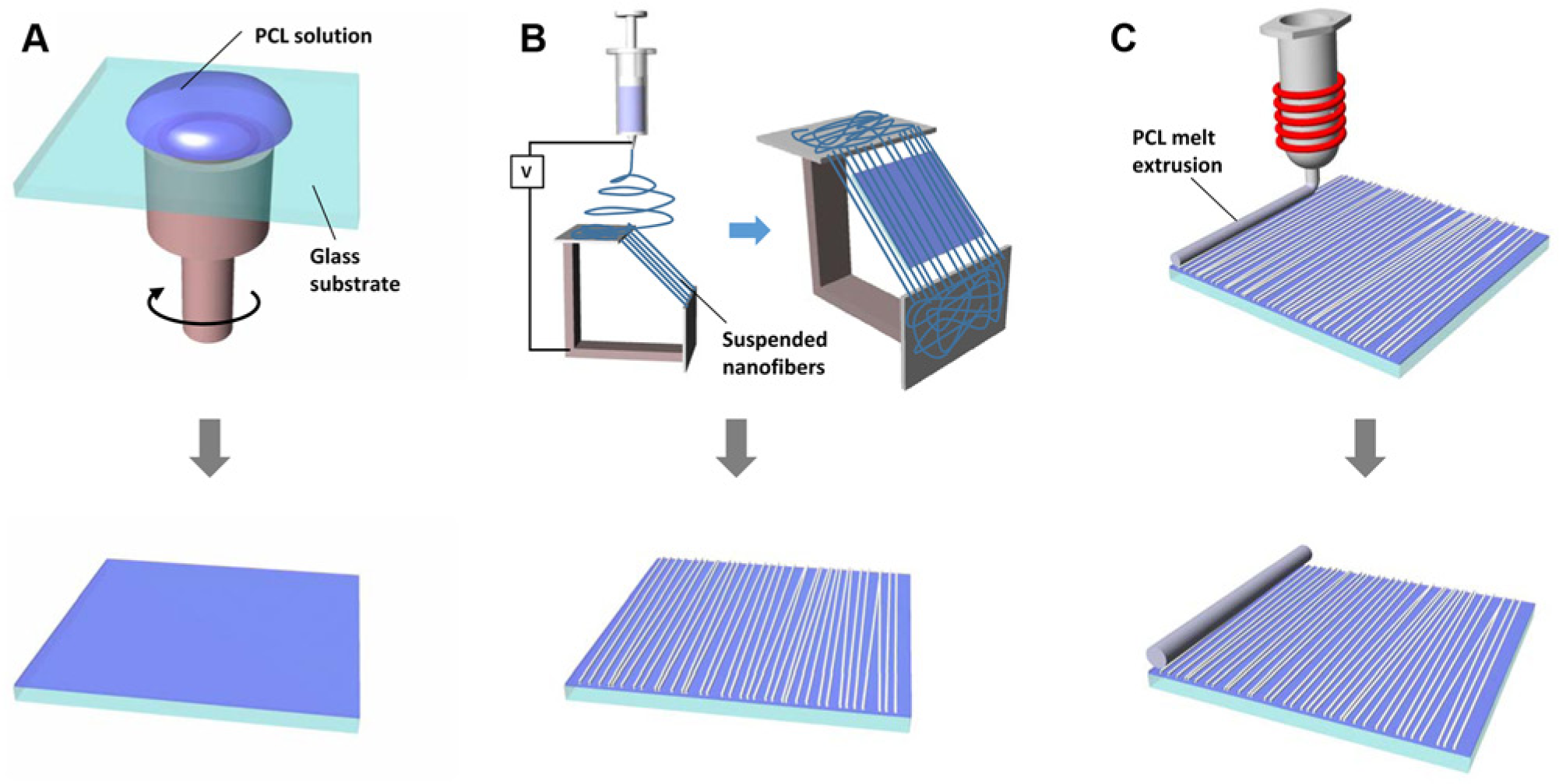
Fabrication process of the hybrid nanofiber scaffold: (
Electrospinning Process and Nanofiber Transfer
The PCL was also dissolved in the mixture of chloroform (Sigma-Aldrich) and dimethylformamide (Junsei, Japan) at a volume ratio of 75/25. Here, dielectric properties generated from the dimethylformamide enhanced electrospinning capability. The solution concentration was chosen to be ~20 wt%, which had been confirmed as a proper condition in the previous work.23,24 The PCL solution was stored in a syringe equipped with a 23-gauge metal needle, which was connected to a high-voltage DC power supply. The syringe module was loaded on a syringe pump and infused at a rate of 1.5 mL/h. The DC voltage of 15 kV was applied to the solution drop formed at the needle tip. The collector for the crop of aligned nanofiber was designed as shown in Figure 1B . Two separate aluminum strips were perpendicularly arranged, and the ejected nanofibers were suspended across the air gap between the strips. Due to the repulsive interaction between the adjacent nanofibers hanging on the strips, well-aligned nanofibers could be obtained. More detailed information about the collecting mechanisms and conditions is described in our previous work. 23 The nanofibers were transferred onto the as-prepared PCL film via spin coating. To vary the scaffold line density, which is determined by the number of nanofibers along a unit distance perpendicular to the direction of nanofiber alignment, the overlapping transfer was carried out in a repetitive manner. The electrospinning time for each transfer was fixed at 1 min, and 3 and 12 transfers were performed, respectively, for low and high density. The resultant nanofiber scaffolds were measured using a scanning electron microscope (SEM) (S-48000; Hitachi, Japan). From the SEM images, the fiber alignment was analyzed by measuring the angles between the longitudinal and vertical directions of the fibers.
Thermal Extrusion of Core Structure for Rolled-up Scaffold
The PCL has good formability for thermal processing due to its low melting temperature at 60 °C. We previously developed a polymer melt deposition system for fabricating a 3D woodpile shape scaffold that comprised a number of thermally extruded microfibers. 24 In this approach, the microfiber-shaped structure was used not only as a core template to provide a tool for rolling manipulation but also as a mechanical support of the overall hybrid architecture. Figure 1C illustrates the thermal extrusion procedure following the prior processes for nanofiber-patterned film fabrication. The system consists of a thermally conductive metal syringe equipped with a micro-precision needle, a coil heater surrounding the syringe module, a pneumatic dispenser delivering compressed air, and a micro-positioning system driven by step motors. When the air pressure was applied to the polymer melts stored in the syringe, the microfiber-shaped polymer melts were extruded out through the microneedle. The initially molten state microfiber was then deposited onto the preprocessed nanofiber film surface and fused with the film as solidified at ambient conditions. The inner diameter of the microneedle was 400 µm, and the processing temperature of the coil heater was set at 150 °C. The applied pressure and the moving velocity of the microneedle were controlled in the range of 550 to 750 kPa and 0.5 to 2 mm/s, respectively. Subsequently, the nanofiber film structure, even with cultured cells on its surface, could be easily rolled up along the fabricated microfiber core structure.
Cell Culture
All reagents used in the experiments related to cell culture were purchased from Sigma-Aldrich unless otherwise specified. C2C12 mouse myoblasts were purchased from ATCC (Manassas, VA) and maintained in Dulbecco’s modified Eagle’s medium (DMEM; GIBCO, Carlsbad, CA) supplemented with 20% fetal bovine serum (FBS; GIBCO) and 1% penicillin-streptomycin (PS; GIBCO). Prior to cell seeding, all scaffolds were sterilized for 1 h under ultraviolet irradiation, treated with oxygen plasma for 1 min, and coated with 10 mg/mL fibronectin for 1 h at room temperature. The cells were seeded onto the prepared scaffold at the density of 2 × 10⁵ cells/cm2 and cultured for 2 days until the cells formed a confluent monolayer.
Immunostaining
C2C12 cells on the scaffolds were gently washed with phosphate-buffered saline (PBS) and fixed with 3.7% formaldehyde solution for 10 min. Fixed cells were washed with PBS three times and immersed in antibody buffer (0.1% Triton X-100 and 2% bovine serum albumin [BSA] in PBS) for 15 min to make the cells permeable and prevent unspecific binding of antibodies. After washing three times with PBS, the cells were then sequentially stained with 4′,6-diamidino-2-phenylindole dihydrochloride (DAPI) solution (1:1000) for the nucleus and phalloidin-TRITC solution (1:400) for the actin cytoskeleton for 40 min each. To prevent photobleaching, the cells were embedded with a small amount of ProLong Gold antifade reagent (Invitrogen, Carlsbad, CA) and observed with fluorescence microscopy (Eclipse Ti; Nikon, Tokyo, Japan).
SEM Measurement
The nanofiber film scaffolds with C2C12 cells were rinsed with PBS and rolled up using the developed method. The samples were fixed with 5% glutaraldehyde solution supplemented with 0.1 M sodium cacodylate and 0.1 M sucrose for 30 min. For further fixation, the samples were treated with 1% osmium tetroxide solution containing 0.1 M sodium cacodylate and 0.1 M sucrose for 1 h. After washing three times with PBS, the samples were slowly dehydrated by immersing them in ethanol solutions of increasing concentration and hexamethyldisilazane (HMDS; J. T. Baker, Phillipsburg, NJ) to prevent collapse of cell morphology. The samples were completely dried in a fume hood overnight and were observed using SEM (S-48000; Hitachi).
Quantitative Analysis
The images of the C2C12 cells stained with DAPI were taken five times for each sample and used for analysis. Cell orientation was determined by the angle of the long axis of nuclei against nanofiber alignment direction. Nucleus elongation was calculated by dividing the short axis length over the long axis length. In a similar manner, SEM images of nanofibers were taken 10 times for each sample and used for calculating nanofiber orientation.
Results and Discussion
Spin Coating of PCL Films
Figure 1 illustrates the process for fabricating a hybrid scaffold consisting of electrospun nanofibers supported on a thin film. The overall scaffolds were made of a well-known biodegradable and biocompatible polymer, PCL, which is widely used for various biomedical applications. Since it has a low glass transition temperature of −60 °C and exists in a rubbery state at room temperature, the PCL-based structure has better mechanical compliance than other biodegradable polymers. This property makes it ideal for use as a flexible scaffold material. In this research, we exploited the shape-deformable characteristic of PCL by employing and integrating three consecutive microfabrication methods of spin coating, electrospinning, and deposition of polymer melt.
At first, we fabricated a thin PCL film using the spin-coating method with variables such as angular speed of spinning and polymer solution concentration. It was observed that the increase of spinning duration time beyond 30 s had no significant effect on the film thickness (data not shown) because the solution almost solidified from the fast evaporation of chloroform that was used as the solvent. Figure 2A shows the correlation between film thickness and spinning speed at three different solution concentrations of 5, 10, and 20 wt%. As seen from the figure, the relatively thin films made from 5 and 10 wt% solutions displayed less dependency on the spinning speed. The variations of film thickness between 1000 and 4000 rpm appeared to be approximately 15% and 18% for the 5 and 10 wt% solutions, respectively. As the solvent evaporation occurred in a very short period during the spinning, the film thicknesses at lower concentrations were less sensitive to the change of spinning speed, and thus their standard deviations were very small, below 0.3 µm. As with the typical spin-coating process, thicker films were obtained as the solution concentration became higher. In the case of 20 wt% concentration, the thickness of all specimens exceeded 15 µm from 1000 to 4000 rpm, and the thickness at 1000 rpm was two times higher than that at 4000 rpm, suggesting a significant dependency on the spinning speed. Figure 2B shows an example of the coated film peeled off from the glass substrate. We found that film thicker than 20 µm was sufficiently rigid to manipulate by any tweezers and was used as a basement substrate for a free-standing nanofiber-transferred scaffold. As observed in other works,25–27 a certain degree of crystallization was found on the surface of PCL film after spin coating, as shown in Figure 2C , D . Here, the spherulitic crystals that were formed regularly on the entire films are believed to yield good mechanical stability and formability. When a thick film was spun from 20 wt% solution, however, some defects such as trapped or burst bubbles were frequently observed. To remove such defective bubbles, the films were heated on a hot plate above the PCL melting temperature (100 °C) and held undisturbed for 10 min. After cooling back to room temperature, a uniform membrane was obtained without bubble defects, as shown in Figure 2E .
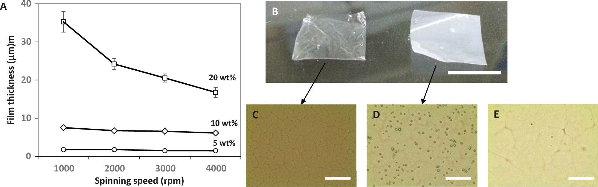
Results of spin-coated films. (
Electrospinning of PCL Nanofibers for Sheet-Type Scaffold
Next, nanofiber-microfilm hybrid constructs were generated by multiple transfers of nanofibers hanging on the void gap collector ( Fig. 1B ). In this way, the density of collected nanofibers could be controlled in a quantitative fashion. Figure 3A , B shows the resulting fibers of average densities of 108 and 384 fibers/mm with 3 and 12 transfers, respectively. Such different densities are expected to yield different contact guidance cues in the cell seeding experiments. As for nanofiber orientation in this scaffold, the fibers placed on PCL film were quantified by measuring the inclined angles with respect to the reference direction. As shown in Figure 3C , D , all transferred fibers were distributed within a narrow range of ±25°, and more than 90% of the fibers were oriented within ±10° to the reference direction. The fiber alignment was nearly reproducible for every single-step electrospinning process, indicating that the nanofiber transfer repetition in both cases of 3 and 12 transfers did not significantly impair the fiber alignment.
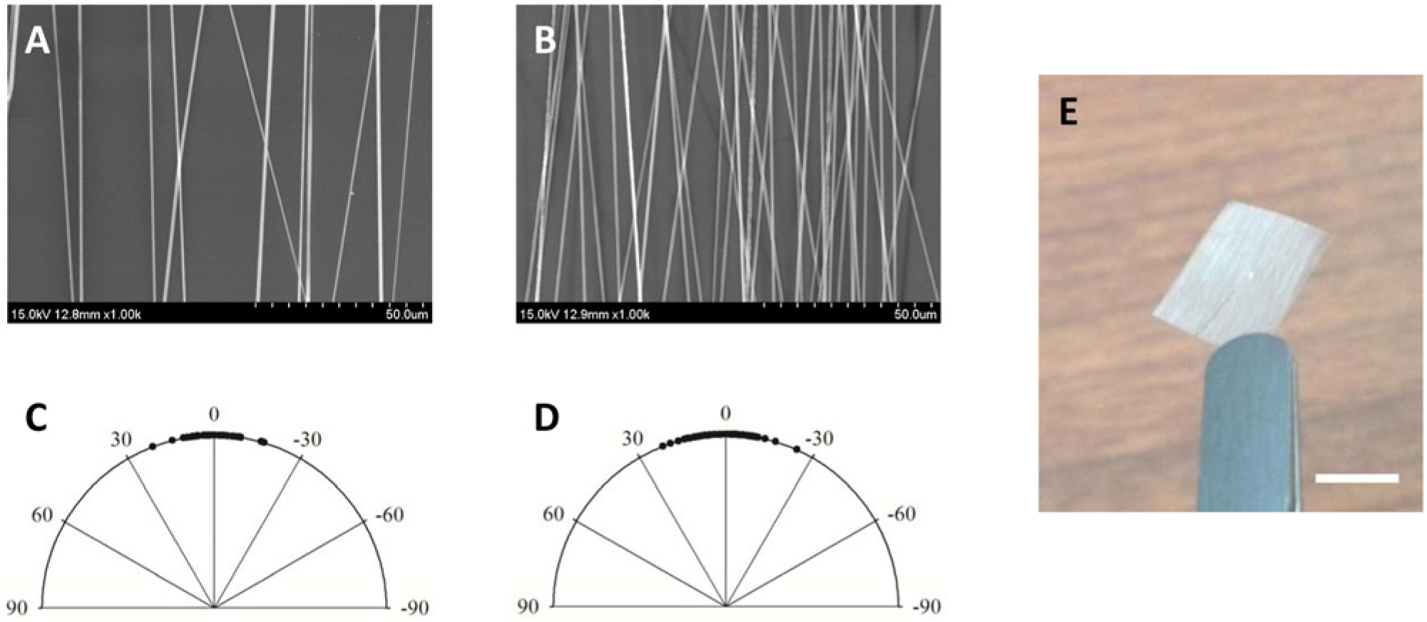
Scanning electron microscope images of the repetitively cropped nanofibers on polycaprolactone films: (
Recently, a number of studies on contact guidance have been conducted via template-assisted techniques such as electrochemical deposition, soft lithography, and nanoimprinting. 28 Although they provide reproducible construction of nanoscaffolds with high precision, the electrospun nanofibers have an advantage in terms of direct transplantation in their initial architecture. To demonstrate the feasibility of the developed nanofiber-based scaffold, C2C12 myoblasts were cultured for 2 days and morphological changes were analyzed from immunofluorescent imaging. We employed three types of scaffolds: (1) flat film without nanofiber and nanofiber scaffold of (2) low density (3 transfers) and (3) high density (12 transfers). As shown in Figure 4B , C , the nuclei and cytoskeletons of cells appeared to align along the unidirectionally oriented nanofibers. Also, the nuclei stained with DAPI showed that the nanofibers on film gave rise to elongated morphology in the direction along the fiber alignment. In contrast, neither the cell alignment nor elongated morphology was shown for the cells cultured on a flat PCL film surface without fibers ( Fig. 4A ).
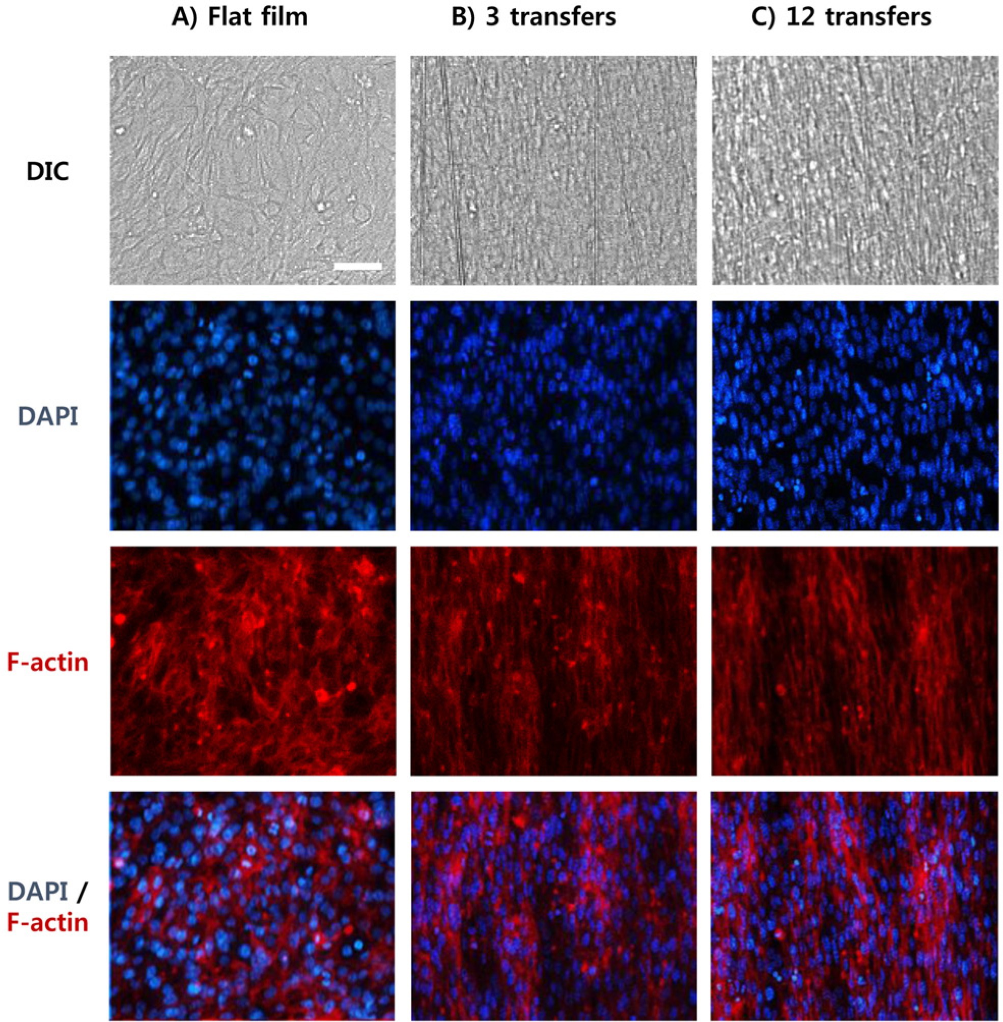
Diffraction interference contrast images (first column) and immunofluorescent staining images of cells cultured on (
For quantification, the distribution of aligned cell morphology was analyzed using angular mapping plots as shown in Figure 5A , B . On the scaffolds without nanofibers, it is seen that the cell alignment and elongation were hardly observed ( Fig. 5A , D ). On the other hand, the cells grown on nanofiber scaffolds with 3 and 12 transfers showed distinct alignment and elongation guided by the nanofibers, as shown in Figure 5B – D . As the nanofiber density increased from 108 (3 transfers) to 384 nanofibers/mm (12 transfers), both morphological changes of alignment and elongation became more pronounced. The correlations between fiber density and cell morphology were identified in accordance with previous work. 29 It is noteworthy that a nanofiber set of relatively low density also provided the desired morphological changes similar to a high-density fiber set, while recognizing that a considerable amount of cells were still not affected by the fibers due to the larger fiber spacing. When considering the confluent state of cultured cells as shown in Figure 4 , the cells aligned directly by nanofibers seemed to affect the shape of adjacent cells due to tight cell-cell interactions even in the presence of the low-density fiber network.
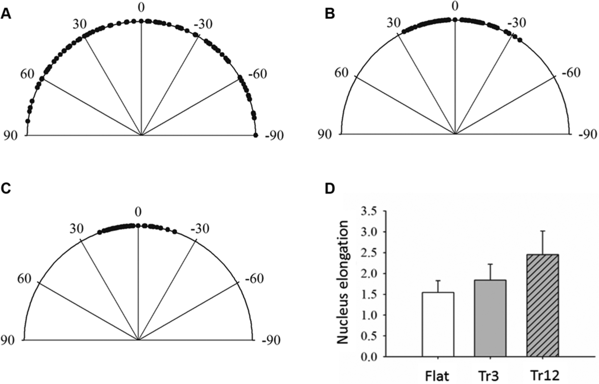
Angular mapping plots to quantify cell alignments of (
Rolling of PCL Nanofibers for Rod-Type Scaffold
One of the crucial factors for an ideal scaffold is to offer a 3D mechanical support for tissue growth. Since electrospun nanofiber structures are too subtle to provide the mechanical support for scaffolds, a number of studies have been made toward a stiff microstructure to overcome the inherent delicacy and 2D limitation of nanofibers.23,30–32 To this end, 3D roll-type nanofiber scaffolds are demonstrated here by incorporating a core microfiber structure by polymer melt extrusion. Figure 6A shows the relation of the extruded microfiber radius versus the velocity of needle movement at two different applied air pressures. These results imply that the dimension of core structure could be adjusted as shown in Figure 6B , C , allowing for a simple route to controlling the final size of rolled scaffold. The dimensional variation could be further tailored by adopting different sizes of microneedles. As mentioned earlier, the microfiber structure was aimed to facilitate the rolling-up process; it was used to pack the planar nanofiber film around the core microfiber as shown in Figure 6D , E . For the basement substrate, a thin film made from 10 wt% solution yielding a thickness less than 10 µm was used, which had enough flexibility to be rolled up.
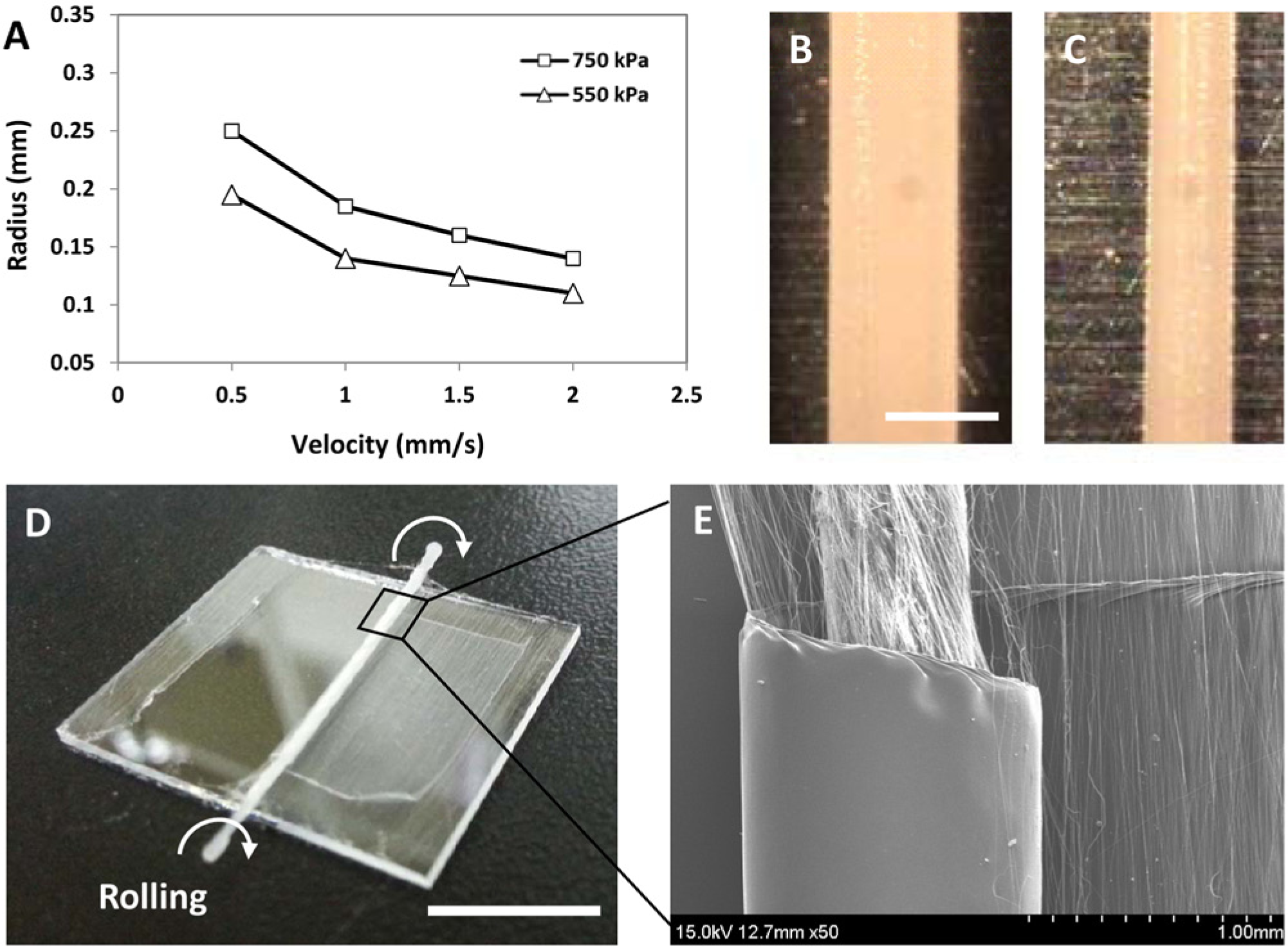
Results of thermally extruded microfibers. (
The rolling-based manipulation was even possible after culturing cells on the nanofiber film. As the region of cell-nanofiber construct on the film could be intact in the course of careful handling of microfiber, the cell structures on the nanofiber scaffold were not damaged during the rolling procedure, as shown in Figure 7 . Also, the nanofiber-induced cell alignments in both cases of 3 and 12 transfer scaffolds were not impaired ( Fig. 7C – F ). The mechanical properties of constituent components, such as nanofiber and micro thin film, were fairly compliable and flexible enough to retain their assembly. It is worthwhile nothing that the ability to embed cells in a rolled 3D scaffold would be beneficial when it is needed to retain the final shape of scaffolds after completing cell culture. If the cell culture were carried out on a 3D shape scaffold by a simple top-seeding method, one would encounter various problems such as difficulties of cell penetration and nutrient/waste exchange. In future studies, more detailed cell experiments with handling the sheet scaffolds will be performed to determine the potential biofunctional significance based on the aforementioned issues of mass transfer through the scaffold.
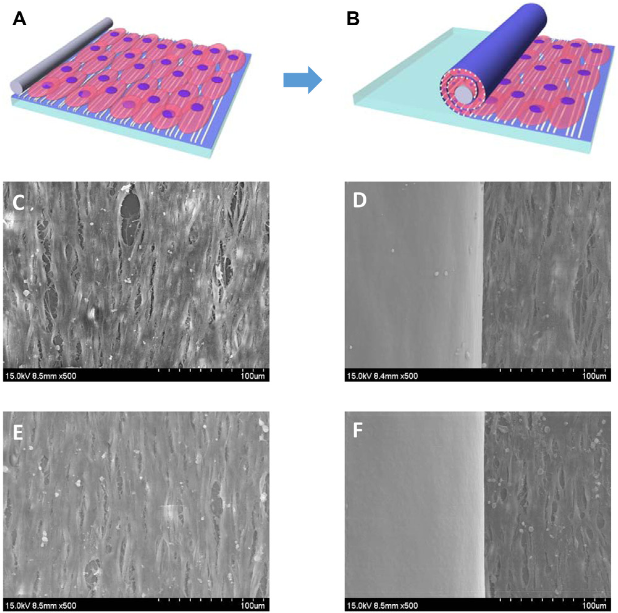
(
In conclusion, the present study has introduced our initial effort to use nanofiber scaffold in practical ways via some physical manipulation such as nanofiber alignment or scaffold rolling. Spin-coated PCL films with varied thicknesses enabled nanofiber manipulation for the development of sheet-type scaffolds. The film thickness could be modulated by adjusting solution concentration rather than spinning speed because of the highly volatile property of chloroform used as the solvent. Well-aligned nanofibers were transferred onto the film multiple times (≤12), which have proven effective to provide contact guidance cues on cultured cells. As expected, the presence of nanofibers yielded morphological changes of myoblasts into aligned and elongated shapes. In addition to sheet-type scaffolds, we developed rod-shaped roll constructs by exploiting the mechanical support of thermally extruded microfiber and the flexibility of the nanofiber-film complex. The rolling process could be carried out without any appreciable damage to cultured cells. These results collectively suggest that the hybrid fabrication method presented here has the potential to overcome various obstacles involved in practical uses of the nanofibrous scaffold in clinical settings or other tissue engineering applications.
Footnotes
Declaration of Conflicting Interests
The authors declared no potential conflicts of interest with respect to the research, authorship, and/or publication of this article.
Funding
The authors disclosed receipt of the following financial support for the research, authorship, and/or publication of this article: This work was financially supported by the National Creative Research Initiative Center for Intelligent Hybrids (No. 2010-0018290) through the National Research Foundation of Korea (NRF) grants. This work was also supported by a Muscular Dystrophy Association (MDA) Research Grant (MDA 255907), and an American Heart Association (AHA) Scientist Development Grant (AHA 13SDG14560076).