
Abstract
Due to the complex structures of living systems, the use of microtechnology to recreate in vivo architecture has exciting potential applications. Living tissues maintain a well-organized three-dimensional (3-D) architecture, with “micro” and “nano” scale features. Microtechnologies offer the new possibility of designing and building sensors and devices in dimensional scales close to that of living tissues.1–2 However, most available microscale systems are two-dimensional, and few 3-D systems are being explored. Therefore, we have developed a versatile technique to create a 3-D microscale hierarchical system for cells and biopolymers. By taking advantage of the contraction of hydrogel matrix biopolymers, one can achieve multiple layers of cells within biopolymers using microchannels, and eventually form a hierarchical layered microstructure of cells and biopolymer. Pressure-driven microfluidics using a syringe pump (Harvard Apparatus, Model 11‘) was applied to transport cells within matrix biopolymers through the channels with controlled flow rates. Flow imaging was used to estimate the shear stress and examine the useful range of flow rates for biopolymer fluids to form the layered structure. The 3-aminopropyltriethoxysilane (APTES) — glutaraldehyde activated glass chips were found to effectively immobilize cell-matrix assemblies. Collagen or collagen-chitosan matrix biopolymers were used as constructs throughout the layers. The final structure was characterized using scanning electron microscopy (SEM). Using this approach, the “neotissue” is formed with cellular and biopolymer components engineered to model the in vivo system.
The use of microtechnology to recreate complex tissue architecture and in vivo conditions can be valuable for tissue engineering. The processes of microfabrication and micromachining use photolithography, along with the deposition and selective etching of thin film layers, to create microscale features on a given substrate. Patterning techniques can control the size, the shape, and the spatial position of cells anchored to a surface. 2 3 Elastomeric microchannels have been used as microfluidic templates to pattern polymers, proteins, and cells. 4 7 Using microfluidics, patterns can be generated by restricting fluid flow to desired regions of a substrate. Engineering “tissue” in vitro may require that cells not only be patterned in specific locations, but also to rebuild the in vivo tissue structure configurations, in order to create organized structures. The extracellular matrix (ECM) is the natural scaffold material in vivo that maintains the 3-D tissue architecture, controls cell proliferation, and regulates the processes of cell motility and cell migration. 8 9 In addition, due to the structural properties of the ECM, it encourages physiological cell growth into a 3-D configuration. The composition and proportion of ECM components can be adjusted to influence cell behavior and better mimic the cellular microenvironment in vitro. 10 Therefore, we used a reconstituted ECM gel for the creation of 3-D patterns in channels.
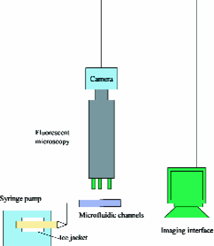
The multilayered structure in microchannels was built through controlled microfluidic delivery. The design of the mask film for microchannels, photolithography of SU-8 - coated wafers, poly(dimethylsiloxane) (PDMS) replication, and techniques of patterning cell-ECM assemblies using microfluidics were described previously. 11 Optical profilometry was used to characterize the width and height of the microchannels. Figures 1 shows that the width is approximately 350μm as designed and the height is approximately 300μm. Figures 2 illustrates the multilayer patterning strategy. In the interval between each cell-matrix delivery, samples were put into an incubator for polymerization and contraction. Flow was traced by an imaging system (Figures 3). In the process of delivering a second layer, flow imaging was carried out using a CCD camera, which was connected to the fluorescent microscope. Cells in the existing cell-matrix layer were labeled red and cells being delivered in the next layer were labeled green. The displacement of the existing layer is measured from the series of images in the delivery process. The time interval between each frame is 0.12 sec. From real-time flow video, the useful range of flow rate was determined and shear stress was estimated. Biopolymer gels such as collagen are biphasic materials with a network of fibrils and interstitial solution. 12 The fibrils form a sparse but highly entangled network that effectively resist shear and extention but have little compressive strength. The shear rheology of collagen gels has been characterized previously. 13 Real-time video microscopy of the flow at different flow rates shows that there are different responses of the cell-gel under the shear stress. For microchannels that are 500μm wide and 300μm high, and cell-gel contraction time set at 6hr, the cell-gel network remains undisturbed at 5μl/min, minimally displaced at 10μl/min, highly displaced at 14μl/min, and dispersed away at 15μl/min. For microchannels with 350μm wide, the effective flow rate to deliver the 2nd layer of cell-matrix is between 5 and 12μl/min. The wall shear stress (τ) of the fluid layer over the existing polymerized layer was estimated using the momentum balance for a Newtonian fluid and assuming parallel-plate geometry: 14
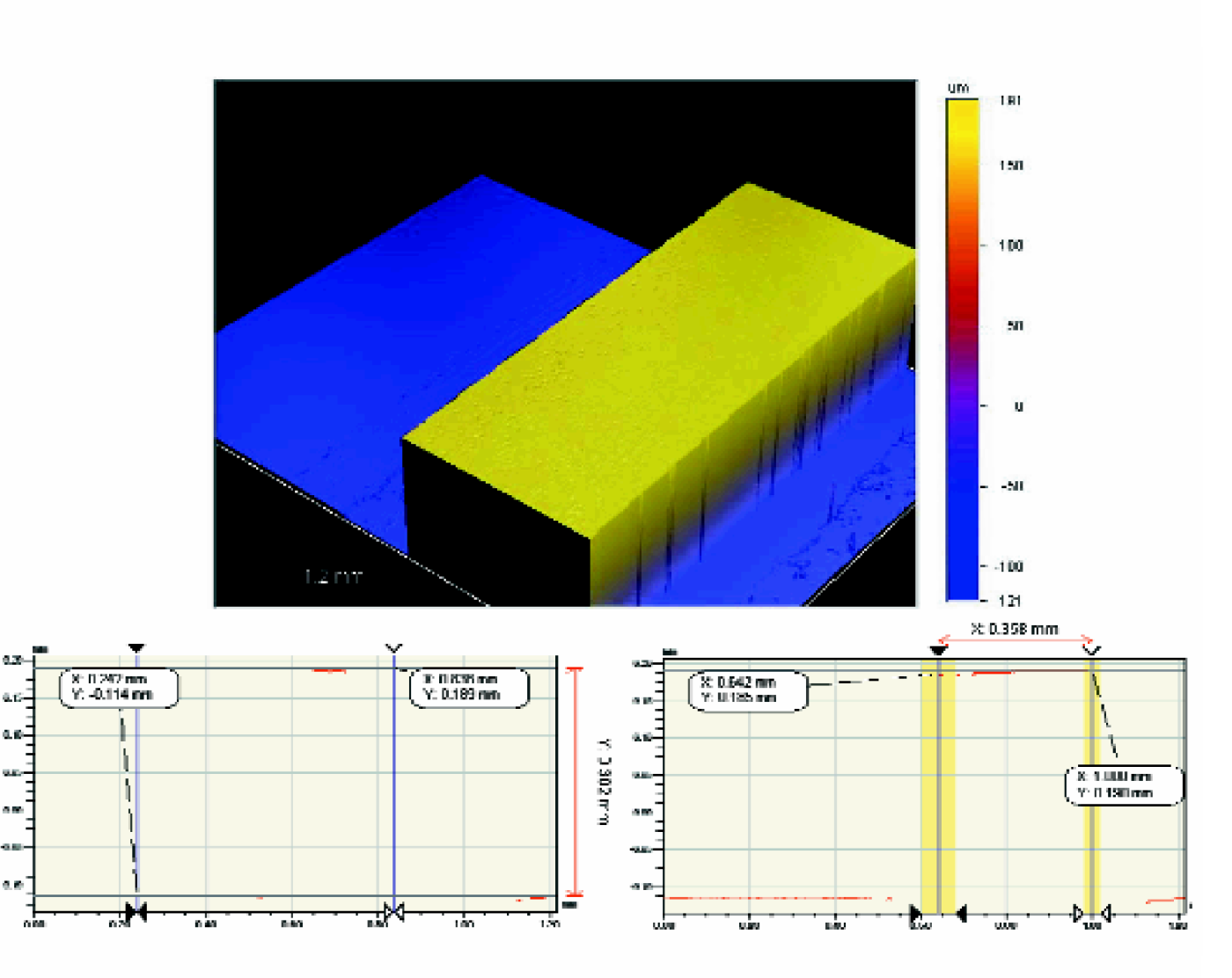
Dimensions of microchannels are measured with the optical profilometer. The width is about 350 um as designed, and the height is 30 um.
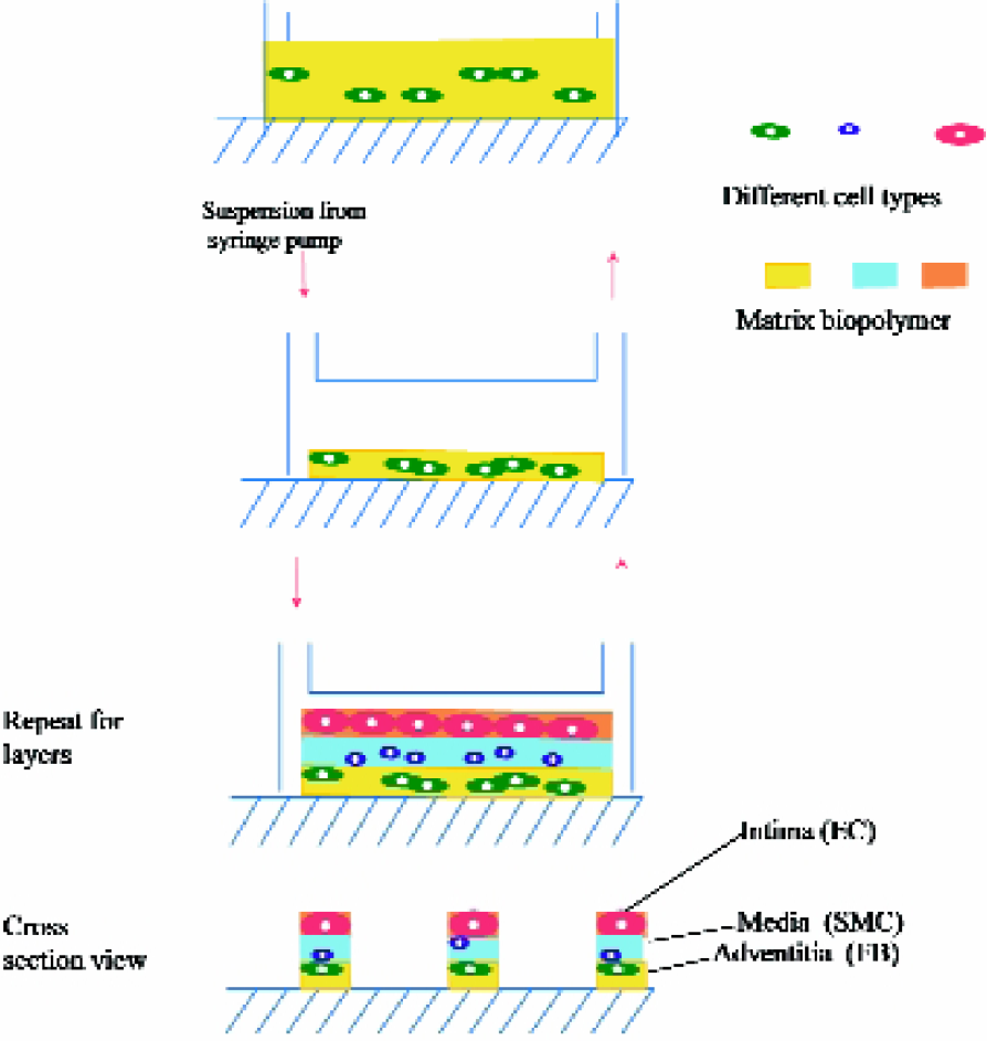
Schematic illustration of our approach using microfluidics to create a 3-D hierarchical system for 3-layer patterning of cells.
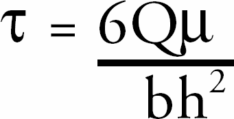
where Q is the flow rate (cm3/s); μ is the viscosity (matrix solution viscosity was estimated to be 10cp or 0.1 dyne s/cm2); 15 16 h is the channel height, which equals to the original height (h0) minus the existing gel height (h = h0 - hg). h0 equals to 300μm, and hg equals to h0 times the contraction percentage; b is the channel width (350μm or 500μm); and τ is the shear stress (dyne/cm2). For the situation when flow rate is 14μl/min, channel width is 500μm, and fibroblasts contraction time is 6hr (gel height is around 0.8 of h0), the resulting τ equals to 77 dyn/cm2.
In order to immobilize the multilayer cell-gel structure on top of the substrate, surface modification of substrates was carried out. Biological molecules such as antibodies can be bound covalently to a silanized silicon surfaces by the use of a linker molecule 17 19 such as glutaraldehyde (GA). Although the collagen gel matrix is a large structural polymer, collagen composed of polypeptide chains, which contain amino groups that are suitable for covalent linkages to supports. Reaction of glass or silicon surfaces with APTES and activation with GA constitutes a frequently used method of protein immobilization. Silanization of silicon or glass substrates with APTES can either be done by incubating the substrate in a water propanol solution or by depositing the silanes on the substrate in a vacuum chamber. 20 For cell and fluorescence applications, we found that the solution-based silanization generated much higher fluorescent background and lower cell viability, compared to the vapor-based silanization procedure. Glass slides or silicon wafers were piranha etched using a mixture of 3 parts of hydroperoxide (30% v/v) and 7 parts of concentrated sulfuric acid for 30min. Slides were then rinsed thoroughly with pure water and blown dry with nitrogen. This treatment generates hydrophilic surfaces with water contact angle of less than 5°. The slides were placed in a preheated vacuum oven, where a small dish loaded with 600μl of APTES was also placed. Then a low vacuum was applied in the oven, and the surfaces were baked at 60°C for 10 min to saturate the volume with APTES vapor. The heat was then turned up to 150°C for 60 min to facilitate silanization of the surface (Figures 4). Thereafter, the silanized slides was immersed in 6% GA for 10 min, followed by a thorough rinse with continuous water flow to totally remove residues of GA. Without proper removal, the residual GA may greatly influence the crosslinking of gel matrix, cell viability and fluorescent background. Slides were then sterilized in 70% ethanol for 20min and dry in the biohood. Finally, PDMS template was laid on the slides with the microchannel structure facing down. Ellipsometry was used to measure the thickness of the APTES thin film and APTES-GA film on the silicon wafer. The refractive index was set at 1.465 for both film layers. The APTES film is about 3nm thick and the GA was about 0.4nm thick. For comparison, fibronectin (Fn)-coated slides were prepared by adding 1ml of 0.1mg/ml of fibronectin solution on hydrophilized slides. After one hour, slides were rinsed with PBS to remove the unabsorbed fibronectin. The same procedure was used to sterilize the slides. Fibronectin is known for its binding site with collagen, so the treated slides may also increase the retention of the collagen matrix. The efficiency of the immobilization of cell-collagen matrix on the slides was evaluated by the percentage of the cell-matrix micro-stripes left on the slides after peeling off and rinsing with PBS, labeled as retention%. Results are shown in Figures 5. The APTES-GA coated surfaces turns out to have highest retention, greater than 90%, which indicates that the cell-gel is strongly immobilized on APTES-GA surface. Because the cell-gel is a 3-D structure, the described immobilization process is different from protein or biomolecular immobilization commonly used. The immobilization of the cell-gel probably occurs through the reaction between APTES-GA on the surface and part of gel chain near the surface, so that the retention percentage is lower than 100%. The immobilization is found to be very important for building multilayer structures inside channels by microfluidics, as well as for the further characterization of the structure after removing PDMS.
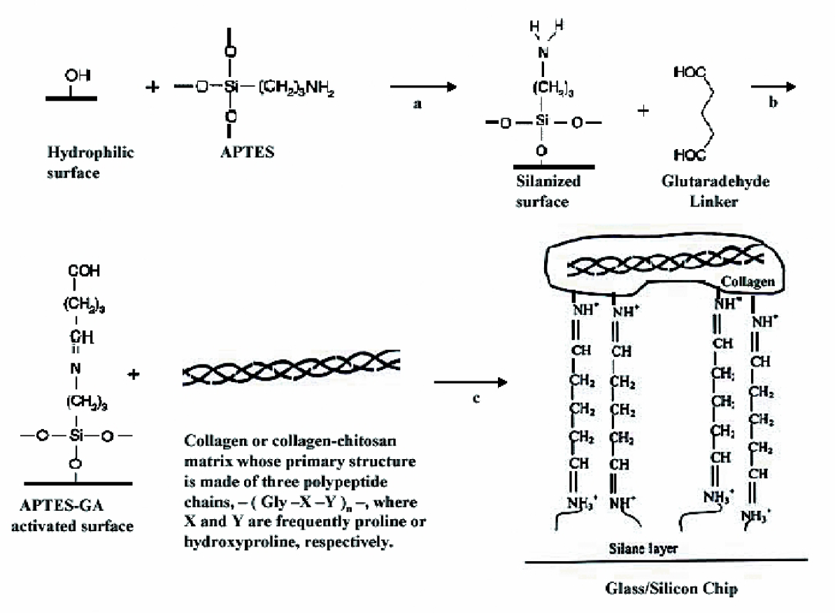
Surface modification procedure involved in cell-collagen gel immobilization. (a) Silanize surface with APATES; (b) Crosslink surface with glutaraldehyde; (c) Add cell-collagen matrix.
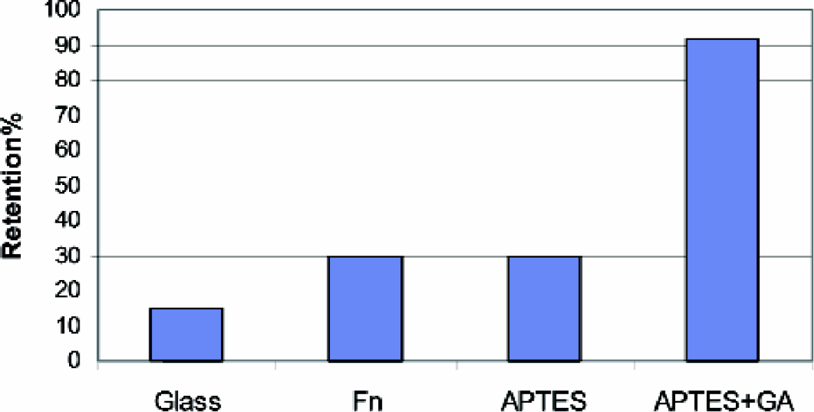
Retention percentage of the cell-gel on the different coated surfaces.
Finally, the resulting structure was characterized using SEM. To illustrate this layered structure, collagen matrix and collagen-chitosan matrix were used. As shown previously, 10 these two types of matrices have different fiber microstructure. For SEM samples, collagen gels and collagen-chitosan gels were fixed with 2.5% glutaraldehyde in cacodylate buffer (PH= 4) for 1hr at room temperature. The specimens were washed three times with cacodylate buffer three times prior to dehydration through a series of graded alcohol solutions. Then they were put into hexa-methyldisilazane for 15 min, before transferring to a dry well and air-drying for about 15 min. Pieces were mounted and some silver paint was added to the edges of the specimen. The Hitachi S-3000N SEM was used for examination. Figures 6 shows the SEM micrograph of a 2-layered structure of materials built inside the channel. The fiber network of the bottom collagen layer is observable under this microscope. However, the top collagen-chitosan layer is more dense and unclear because chitosan composite in the matrix greatly charges the electron beams. The thickness of the top collagen-chitosan layer and bottom collagen layer is approximately 20μm and 40μm, respectively. Because the SEM sample fixing procedure introduces crosslinking and dehydration, this thickness does not equal to the actual value. In addition, since a blade was used to cut the sample at the viewing end, the end was deformed. However, our measurement indicates the proportion of the two layers in the channel.
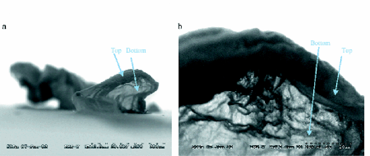
SEM micrograph of the two-layer structure of the model. (a) The microstripe was lying on the surface of the substrate. (b) The structure was viewed from one end of the stripe. Arrows are pointing to the top (collagen-chitosan) and bottom (collagen) layers.
In conclusion, we introduced a microfluidic method to build a 3-D heterogeneous multilayer structure inside microchannels. Using this approach, patterning of biological microstructures can be achieved not only on the surface (2-D), but also over the thickness of the construct (the third dimension). The “neotissue” formed of different types of cells and biopolymer components can be engineered to model in vivo living systems. Thus, this approach provides a novel solution to fabricate hybrid biopolymers and hierarchical heterogeneous “neotissues”. This technology will be useful to create more complex tissue structures as well as understand fundamental processes in cell biology.