
Abstract
Electrospinning is a versatile technique for production of nanofibers. However, it lacks the precision and control necessary for fabrication of nanofiber-based devices. The positional control of the nanofiber placement can be dramatically improved using low-voltage near-field electrospinning (LV-NFES). LV-NFES allows nanofibers to be patterned on 2D and 3D substrates. However, use of NFES requires low working distance between the electrospinning nozzle and substrate, manual jet initiation, and precise substrate movement to control fiber deposition. Environmental factors such as humidity also need to be controlled. We developed a computer-controlled automation strategy for LV-NFES to improve performance and reliability. With this setup, the user is able to control the relevant sensor and actuator parameters through a custom graphic user interface application programmed on the C#.NET platform. The stage movement can be programmed as to achieve any desired nanofiber pattern and thickness. The nanofiber generation step is initiated through a software-controlled linear actuator. Parameter setting files can be saved into an Excel sheet and can be used subsequently in running multiple experiments. Each experiment is automatically video recorded and stamped with the pertinent real-time parameters. Humidity is controlled with ±3% accuracy through a feedback loop. Further improvements, such as real-time droplet size control for feed rate regulation are in progress.
Keywords
Introduction
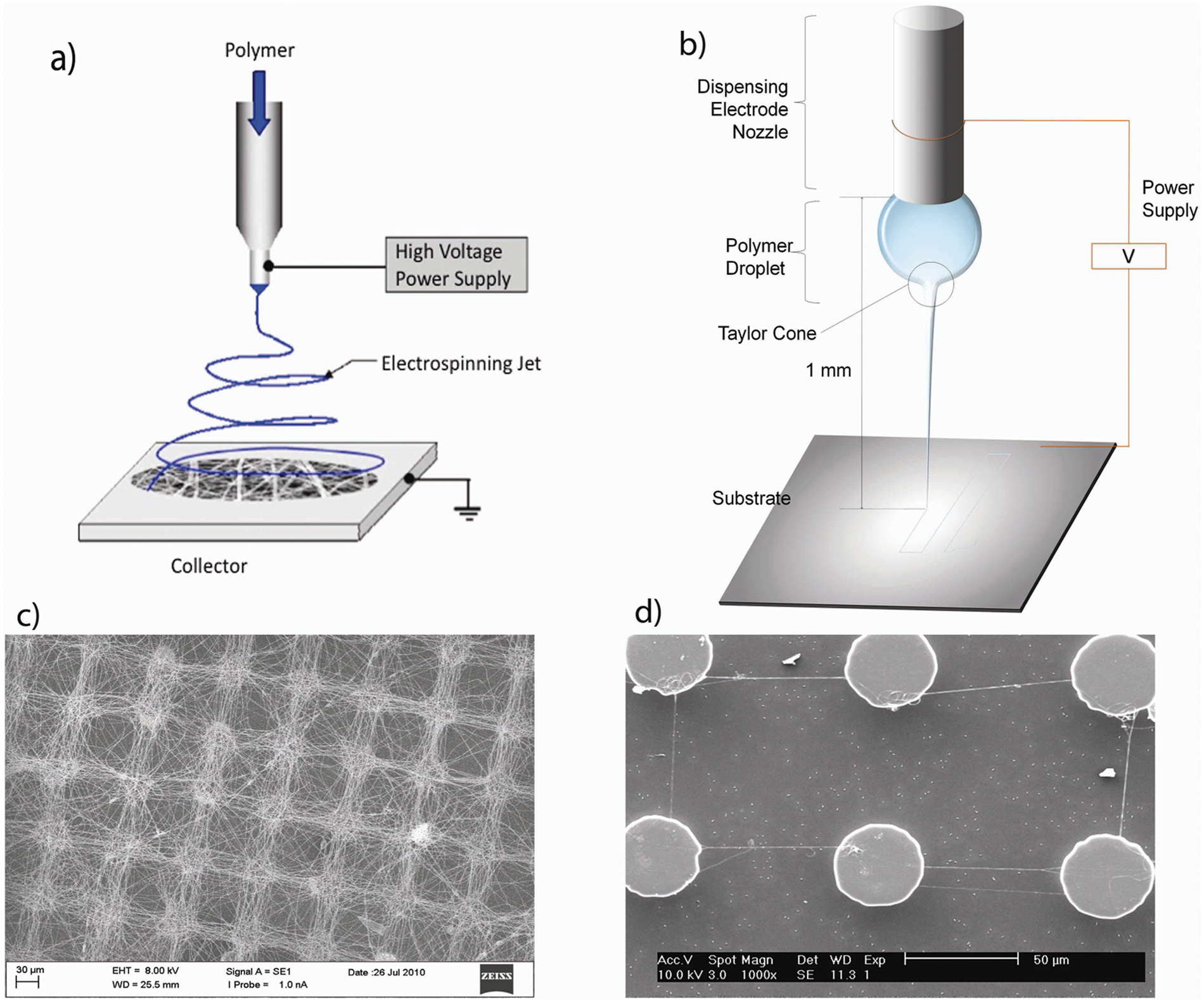
Electrospinning is widely used to carry out large-scale inexpensive production of polymeric and carbon nanofibers.1–12 Electrospinning involves applying a high voltage between a polymer solution and a grounded collector as a substrate, shown in Figure 1 . Traditionally, a polymer source is contained in a syringe with a nozzle electrode separated from the substrate by 10 to 15 cm, and the applied voltage is in the range of 10 to 15 kV, in a configuration known as far-field electrospinning (FFES).13–16 The charged polymer solution is pulled toward the grounded substrate in the form of a thin jet developed by an interplay between the polymer solution’s surface tension and electrostatic forces of the electric field. At the initiation of the jet, the applied high voltage produces strong electrostatic forces that overcome the surface tension in the polymer droplet at the end of the dispensing nozzle/needle (see Figure 1 ). As a result of this disruption, a polymer jet is issued from the droplet, producing a cone-shaped interface known as a Taylor cone. The polymer jet travels straight for the first few millimeters before the imbalance in the surface charge distribution causes the jet to experience bending instability, resulting in a whipping action. 17 This whipping action stretches the polymer jet and effectively reduces the jet diameter from a few microns to tens of nanometers. The fiber’s whipping action also makes it nearly impossible to control where the FFES fiber lands on the substrate.1,7,18
Far-field electrospinning (FFES;
The problem of random whipping of nanofibers can be addressed by reducing the distance between the nozzle and the substrate to less than a few millimeters, so that fibers land on the substrate before the onset of whipping. This configuration, known as near-field electrospinning (NFES), was suggested relatively recently.19,20 In an NFES setup, initiation of electrospinning requires high voltages to overcome surface tension, leading to a thick jet (several microns). Our group has found that production of thinner stable fibers necessitates operation at a lower voltage, and our latest results demonstrate that in this way, even sub–20-nm diameter nanofibers are possible at a bias as low as 300 to 200 V when using superelastic viscoelastic polymers. This new technique is called low-voltage near-field electrospinning (LV-NFES). The present article addresses the automation aspects of the LV-NFES setup, while detailed experimental results on the LV-NFES technique are discussed in a separate publication. 21
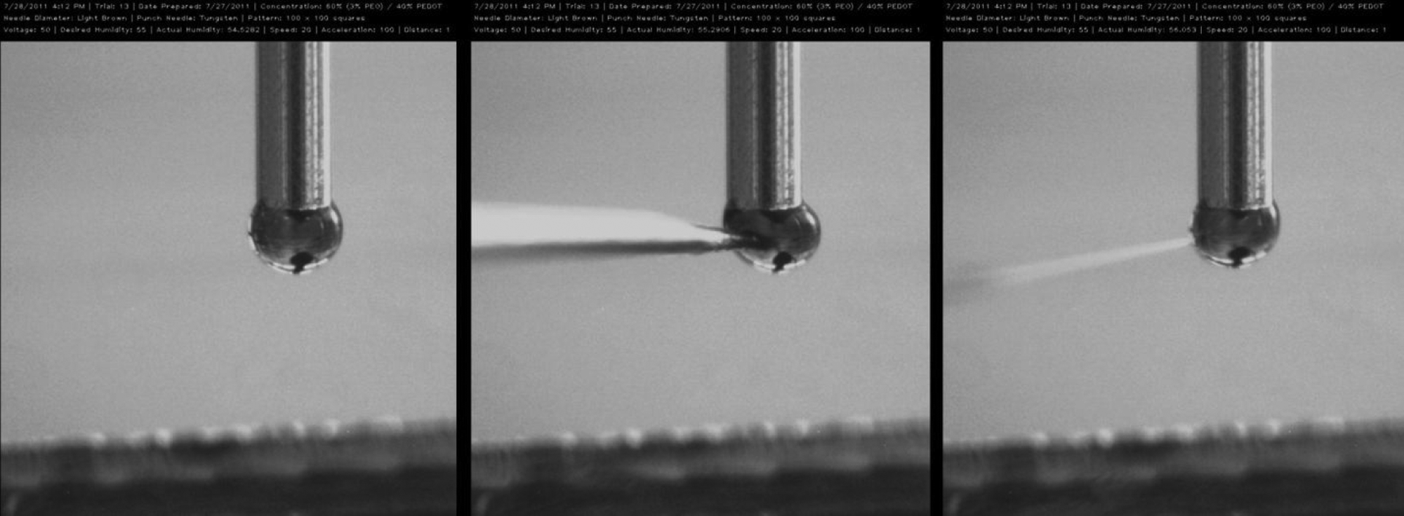
To avoid the need for a high initiation voltage, the surface of the polymer droplet is artificially disrupted by poking the droplet with a sharp needle to create a localized region of a very high electric field on the droplet’s surface and to overcome the surface tension, initiating the electrospinning process. The resulting jet is stable and can be easily and precisely targeted onto a stationary or moving substrate, as shown in Figure 2 . The LV-NFES setup is very sensitive to minor changes in parameters such as penetration depth of the initiation needle, distance between the polymer droplet and the substrate, speed of the substrate with respect to the stationary nozzle, humidity, and temperature. These parameters need to be coordinated and well controlled, tasks best accomplished with the use of a computerized automation. The computer interface also makes it easier for the user to select and edit the parameters between different trials.
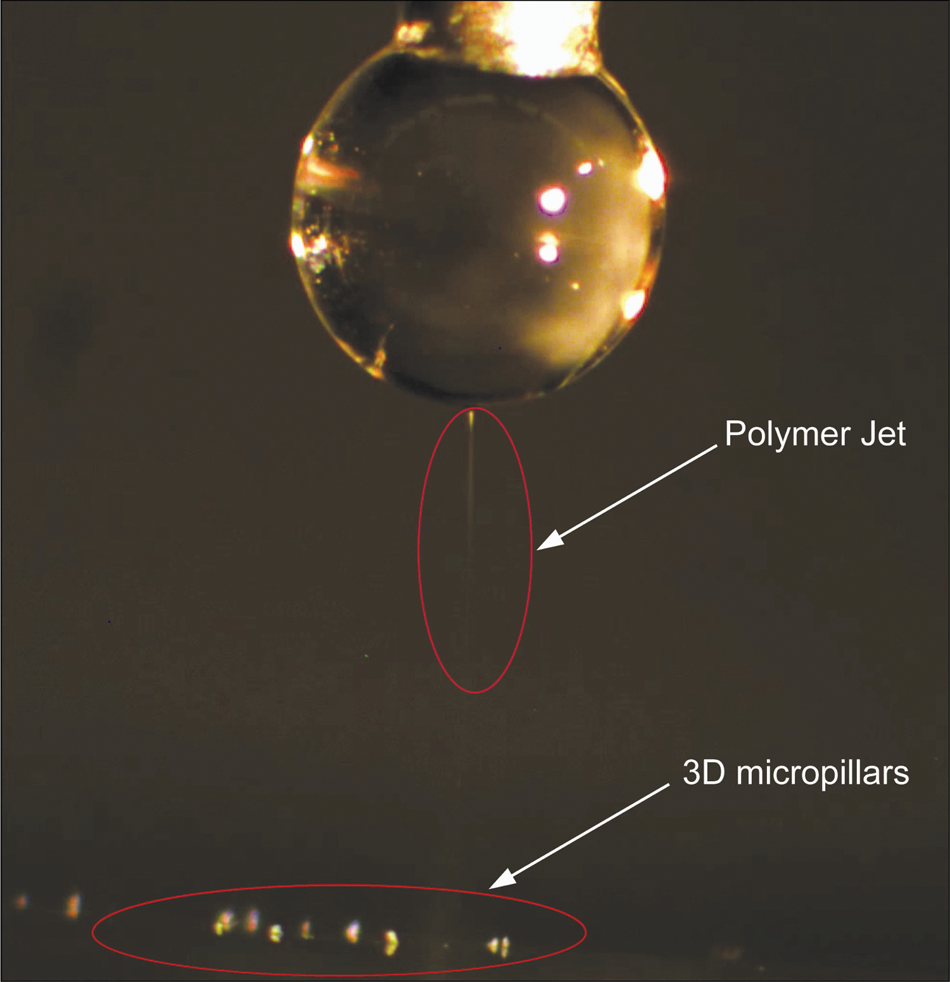
Electrospinning on 3D micropillars with the low-voltage near-field setup. The polymer jet travels straight, as highlighted by the red ellipse.
The setup we devised consists of multiple computer-controlled components, as shown in Figures 3 and 4 . A motorized XY stage moves the substrate underneath the dispensing nozzle. A linear actuator is used to guide the needle as it punctures the polymer droplet to initiate the electrospinning process. A pneumatic pump connected to the syringe dispenses the polymer. A video camera coupled to a microscope monitors and records the electrospinning process. The entire setup is placed within a closed chamber, and a humidifier maintains a preprogrammed level of humidity within the enclosure (using feedback control from a humidity sensor). The setup is stationed on a vibration-free optical table. All components are connected to a computer running custom software that controls most of the electrospinning parameters.
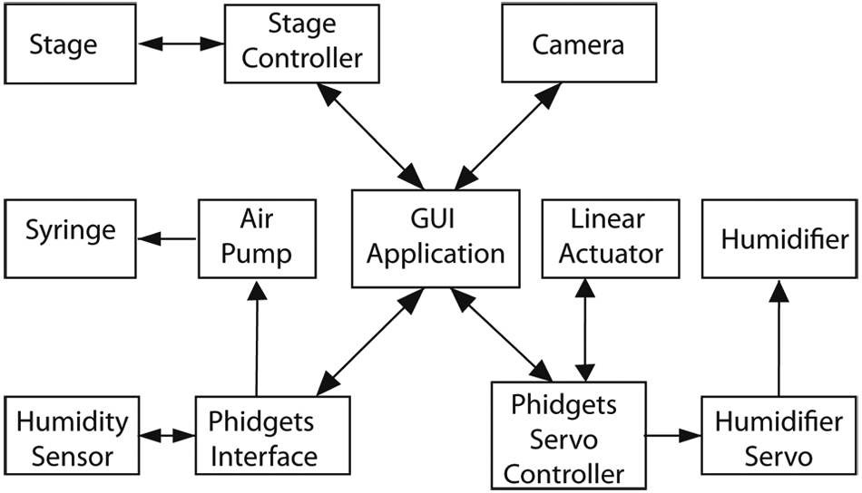
A block diagram for the control architecture implemented for low-voltage near-field electrospinning setup automation.
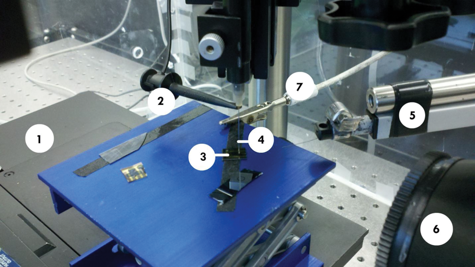
Stage and initiator setup. (
Stage Control
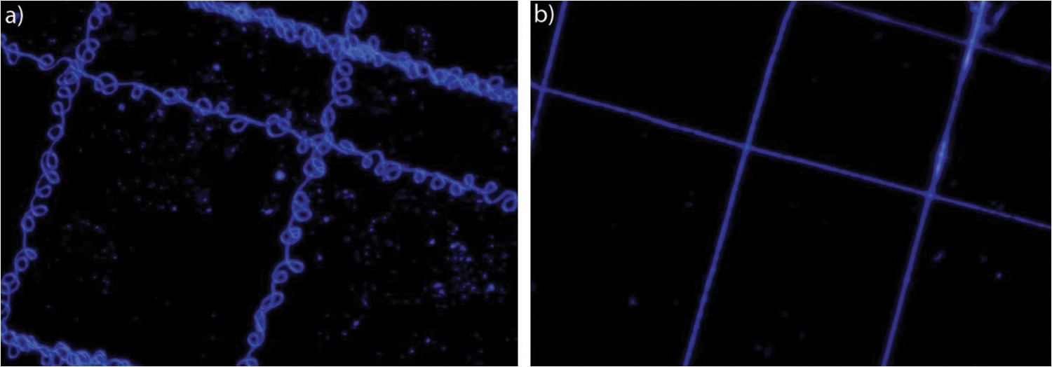
The relative speed of the moving stage (that holds the substrate) with respect to the electrospinning nozzle affects the thickness of the nanofibers. If the speed of the substrate is slower than the rate at which the polymer is being pulled down by the electric field, the fiber starts to coil up, as shown in Figure 5a . On the other hand, if the substrate moves too quickly compared with the deposition rate, the polymer feed rate into the jet is unable to keep up with the deposition, and the fiber breaks prematurely. Therefore, to produce straight and continuous fibers of desired thickness, it is necessary to exercise precise control over the speed and acceleration of the stage (see Figure 5 ). It is also possible to suspend nanofibers between 3D substrate features, such as microposts, using proper stage control (see Figure 1d ). 21
(
The Prior Scientific H128 Motorized Stage that we are using for substrate movement offers a resolution of 1 µm in the X and Y directions and accepts motion commands through a standard RS232 serial communications port. The user draws a desired deposition pattern in CAD software (such as Autocad, Solidworks, etc.) as an assembly of individual lines and saves the pattern in DXF format. Our custom software then reads the DXF file and generates a list of linear motion commands for the stage that is saved to a text file. The user is also given the option of adjusting the maximum speed and acceleration of the stage in the software through a graphic user interface (GUI; discussed below). The motion commands are then sent to the stage controller in the form of individual position coordinates along with the speed and acceleration specifications, after the electrospinning jet has been initiated and the nanofibers start to be deposited onto the substrate.
Initiation Control
A crucial part of the LV-NFES process is the initiation of the electrospinning process using manual disruption of the polymer droplet with a sharp tungsten or glass tip, as shown in Figure 6 . We have observed that the depth to which the initiation needle is driven within a droplet is crucial in successfully initiating the process. We observed that if the needle is driven too deeply into the droplet, the initiated fiber is relatively thick, and the electric field pulls the fiber down too quickly, breaking the fiber in the process. However, if the initiation depth is insufficient, the polymer jet is too thin and mechanically weak to withstand the electrostatic stretching force. Because the diameter of the droplet used is usually no larger than 0.5 mm, it is impossible to implement the manual droplet poking “by eye,” and automation is necessary to control the initiation process. We employ a Firgelli L12 100 mm 210:1 linear actuator to accomplish this task. The actuator is mounted with a microtipped tungsten needle for pricking the polymer droplet, as shown in Figure 4 . The linear servo actuator is controlled through pulse width modulation (PWM) position signals. A Phidgets 1061 Advanced Servo 8 motor controller provides the PWM signals through an easy-to-use graphic computer interface. This controller was also used to implement humidity and droplet size control discussed later, through an application called Phidgets Interface embedded in the GUI application (see Fig. 3 ).
Near-field electrospinning process initiation. A needle disrupts the surface of the droplet and pulls out an initiation fiber, which is then pulled down by the electric field to start the electrospinning process.
The software that we developed enables two possible ways to use the actuator. The first is a simple track bar slider that corresponds to the position of the actuator. The maximum and minimum positions of this track bar can be preset and allow the user to calibrate the position of the poking tip with respect to the center of the nozzle before dispensing the polymer droplet. The poking depth is then defined by adding or subtracting a percentage of the polymer droplet radius (obtained by the bubble recognition program discussed later) to the above calibrated nozzle center position. The second preset control is a button-activated sequence that automatically extends the actuator to the maximum preset position at maximum speed and then retracts after the maximum position is reached. The controller tracks the current running through the actuator and sends the retract command only when the current hits zero, allowing the actuator to fully extend before retracting. This button control is then used to automatically initiate the electrospinning process after droplet formation and calibration described above.
Humidity Control
Humidity is another crucial parameter in the LV-NFES process. Most of the polymer formulations we use with the LV-NFES setup are dissolved in water, which evaporates as the polymer droplet is suspended in air. This raises the concentration of the polymer in the droplet and eventually dries it out completely, and the LV-NFES process cannot be sustained. In some cases, this drying out of the droplet can happen within a minute, which dramatically limits the length of continuous nanofiber deposition. We have found that for most polymer formulations, the most stable and continuous patterns are produced at a humidity of about 60% R.H. We believe that this is due to the plasticity of the polymer jet in flight (between the nozzle and the substrate). At lower humidity, we see some jets dry out before landing on the substrate, forming standing fibers. When humidity is too high, the polymer is dispensed as droplets, not fibers. To control the humidity level, the setup was enclosed in a plastic box. A humidifier with a feedback control (provided by Phidgets 1125 humidity/temperature sensor) maintains the preprogrammed humidity level within ±3% R.H.
Droplet Size Control
For continuous electrospinning, the droplet (from which the Taylor cone is produced) should be replenished from a larger reservoir at the volumetric rate equal to that of the loss through fiber production and evaporation. Thus, the droplet size can give an indication for the need to increase or decrease the applied voltage (or pressure) to maintain a stable continuous deposition process. We are currently working on an image recognition program that determines the size of the polymer droplet (see Fig. 7 ). This information is used to trigger an increase or decrease in the air pressure produced by the IEI Accura 9 Automatic Air Dispenser attached to the syringe that contains the polymer.
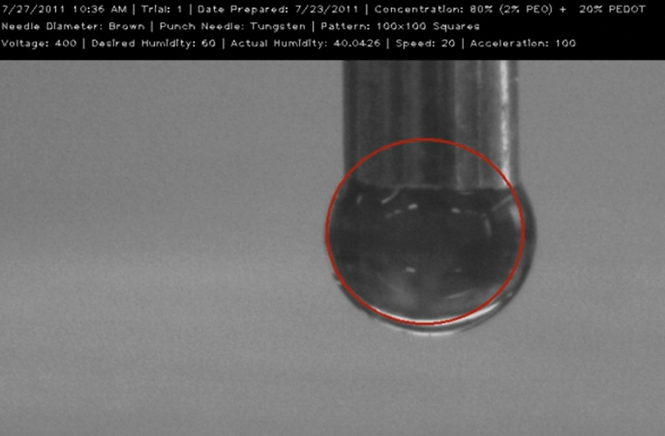
Detection of the droplet size. The red circle generated by the software grows to match the outlines of the droplet.
User Interface
To bring all of the above-described controls together, a GUI was developed (shown in Fig. 8 ). This interface facilitates user interaction with different controllers embedded in the GUI application and is built on the C#.NET platform. The user fills out the parameters for multiple electrospinning sessions in an Excel file, loads the current session parameters into the GUI application, and initiates humidity control. Meanwhile, the initiation needle’s position is calibrated, and the polymer droplet is formed. The user then selects the CAD file with the desired pattern, initiates the electrospinning process (once desired humidity is reached), and starts the stage program to write the nanofiber(s). The video, automatically stamped with all parameter information, is saved on a hard drive in real time.
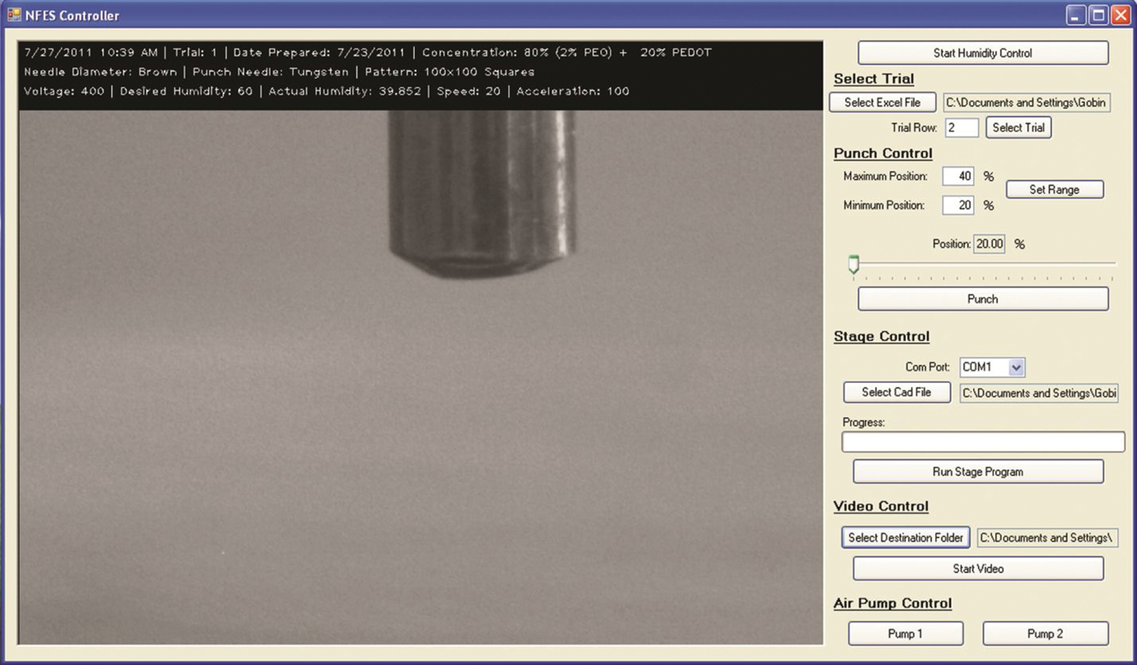
The graphic user interface used to control the semiautomated low-voltage near-field electrospinning setup.
Conclusion
In this work, we developed an automation strategy for LV-NFES that improves precision and control over electrospun nanofiber deposition onto both 2D and 3D substrates. Several crucial parameters such as humidity; stage position, velocity, and acceleration; and movement of the needle-tipped actuator have been successfully controlled and coordinated using computer-interfaced components. The GUI computer software ties together the controls and recording of the electrospinning process. We devised an automation strategy for the LV-NFES process that will play a critical role in the further adoption of this technique for mass production of plastic electronics, photonics, MEMS, piezoelectric energy harvesters, microresonators, and other devices.
Further design improvements are under way. At this stage, the droplet poking controls (to initiate the electrospinning process) are not fully automated through the main program. Also, parameters such as nozzle-to-substrate distance and continuous voltage control need to be automated and integrated into a single platform. In addition, we intend to improve the stage control further by employing piezoelectric stages that can achieve constant velocity with lower lag time. However, piezoelectric stages have a narrow range of movement and will be combined with stepper motor stages to accommodate larger substrate sizes. Another key to improved process control will be the detection of the onset of the electrospinning process. We plan to integrate a high-sensitivity, high-dynamic-range current sensor that can monitor the conductivity of the forming fiber and foresee interruption in the electrospinning process through change in this conductivity.
Footnotes
Acknowledgements
The authors would like to thank Dr. Horacio Kido of Rotaprep Inc. for his generous support in the implementation of this project. We also acknowledge the World Class University (WCU) program (R32-2008-000-20054-0) of the National Research Foundation of Korea funded by the Ministry of Education, Science and Technology.
Declaration of Conflicting Interests
The authors declared no potential conflicts of interest with respect to the research, authorship, and/or publication of this article.
Funding
The authors disclosed receipt of the following financial support for the research, authorship, and/or publication of this article: This research was supported by the National Science Foundation grant NIRT-0709085 and by UC Lab Fees Award 09-LR-09-117362.