
Abstract
Technological advances in solid organ tissue engineering that rely on the assembly of small tissue-building parts require a novel transport method suited for soft, deformable, living objects of submillimeter- to centimeter-length scale. We describe a technology that utilizes membrane flow through a gripper to generate optimized pressure differentials across the top and bottom surfaces of microtissue so that the part may be gripped and lifted. The flow and geometry parameters are developed for automation by analyzing the fluid mechanics framework by which a gripper can lift tissue parts off solid and porous surfaces. For the axisymmetric part and gripper geometries, we examine the lift force on the part as a function of various parameters related to the gripper design, its operation, and the tissue parts and environments with which it operates. We believe our bio-gripping model can be used in various applications in high-throughput tissue engineering.
Introduction
Recent advances in high-throughput three-dimensional (3D) cell culture have greatly facilitated the production of cell spheroids for use in cancer research, drug discovery, and tissue engineering.1–4 In addition to possessing cell density comparable to that of native solid organs, these self-assembled tissues are characterized by high viability, enhanced differentiation, and metabolic activity, making them well suited as building blocks for scaffold-free tissue constructs. 5 The next step toward engineering these constructs for the ultimate goal of solid organ orthotopic transplantation lies in developing a robust method for manipulating and assembling the individual tissue-building parts.
A potentially transformative approach for the engineering of solid organs is the generation of more complex microtissue geometries beyond the spheroid. Depending on the design of the mold, cells will coalesce to form geometries such as toroids, rods, or more complex lattice-like structures. 6 The resulting tissue “parts” are typically thin and planar and contain one or more lumens. Lumens are useful due to the diffusive transport, which limits the thickness of tissues to prevent hypoxia. 7 Second, following the completion of self-assembly, the mold is transported to a culture media bath environment and inverted to release the part that then lies submerged under culture medium. The part is then lifted by a fluid-driven gripper, which acts as a “claw machine” to pick up the tissue part, transport it to the build head, rotate the part about the z coordinate for proper alignment, and finally place it atop a perfused tissue stack composed of previously placed parts ( Fig. 1a ).8,9 Lastly, the aligned lumens of the placed parts form cylindrical conduits through which culture medium is drawn, thus perfusing the large tissue construct and ensuring the maintenance and viability of the tissue as the individual parts fuse into one contiguous tissue.
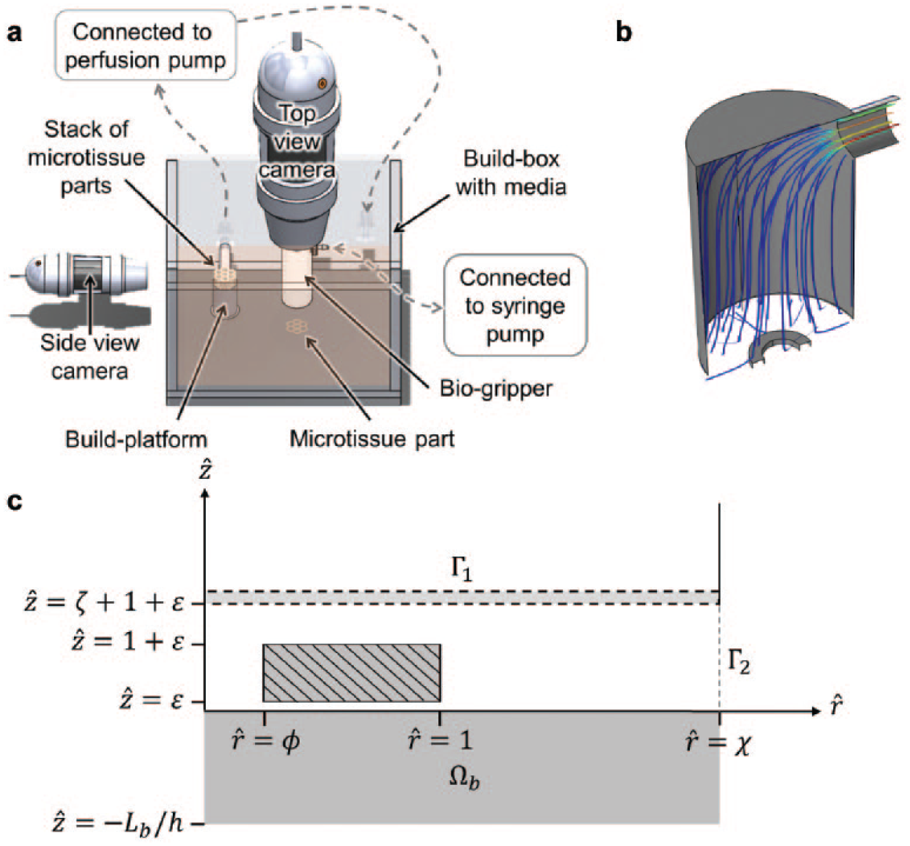
Gripper and part schematic overview. (
The micromanipulation of single cells in suspension has been demonstrated extensively in many techniques, such as electrostatic deflection, 10 optically actuated dielectrophoresis, 11 and a multitude of hydrodynamically driven microfluidic focusing schemes. 12 Strategies for the transport and manipulation of spheroids are mostly limited to pipetting, which can generate large shear stresses and is not suited for individual spheroid handling. 13 The transport of thin sheet-like tissues composed of 105 to 107 compacted self-aggregated cells, however, remains an unexplored problem. Their size, deformability, and need for precise handling require a novel transport technology that could be applied to not only millimeter-scale tissues, but also any suspended soft material. In this article, we develop a basic framework for a fluid-driven claw machine for soft microtissue translocation, investigating the hydrodynamics of part gripping and obtaining the optimal operational parameters necessary for automatic tissue handling. From a fluid mechanics perspective, we describe the flow and stress fields imposed by the gripper, as well as determine the effects of various parameters related to the gripper design, operation, and part characteristics.
Theory and Methods
Problem Description
We considered a tissue part within a nutrient-rich fluid culture medium and investigated the effect of an imposed suction flow. Typical parts may range in diameter from 10−4 to 10−2 m and are lifted by a gripper head whose width is comparable to but not exceedingly greater than that of the part. The gripper is essentially a hollow tube connected to a pump supplying negative pressure ( Fig. 1b ). The end of the gripper is sealed by a thin, low-porosity polymer membrane that can hold the part when sufficient suction flow is applied. Because the part is very thin and lies on a flat surface, an impinged radial flow is produced when the gripper is moved into place above the part and activated.
We idealized our part-gripper system as an axisymmetric two-dimensional flow as depicted in
Figure 1c
. We chose a cylindrical coordinate system (r, z) for simplicity, though generalization to any system is straightforward. All gripped parts were of the same density of 1050 kg/m3. Individual parts of outer radius w, inner radius
Governing Equations and Nondimensionalization
At steady state, we constructed the continuity and momentum conservation equations for Newtonian incompressible Stokes flow to solve for the velocity

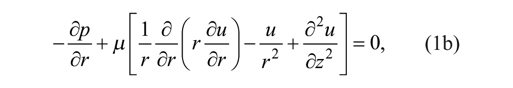
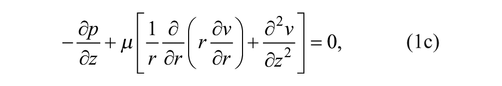
where
We nondimensionalized the continuity and momentum equations to understand relevant parameters. The length scales in the r (radial coordinate) and z (axial coordinate) directions were normalized as
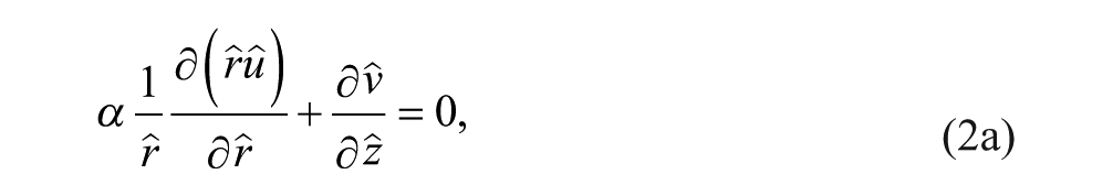
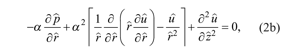
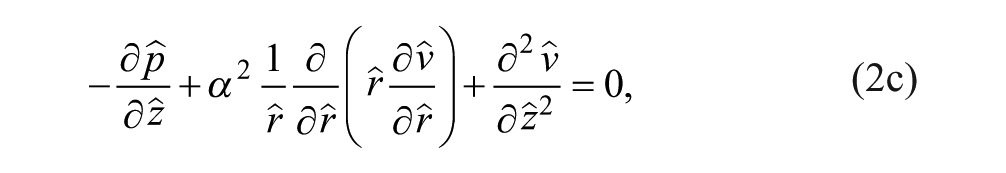
where a α ≡ h/w is the height-to-width aspect ratio of the tissue part and the dynamic pressure is made dimensionless by
Simulation Domain and Boundary Conditions
The problem at hand was simplified and represented by a cylindrical, axisymmetric domain Ω that extends a distance χ in the
Two gripping schemes, solid (SBG) and porous (PBG) bed gripping, were examined. For SBG, the
The surface of the part was discretized into n surface elements. For each element i, the force
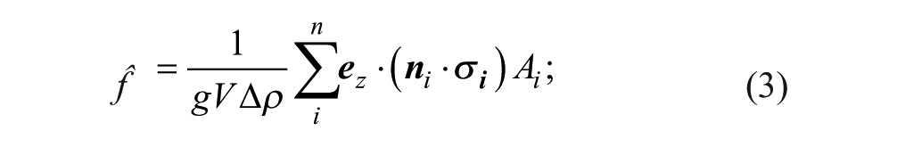
thus, in order for the hydrodynamic force to overcome the part weight and lift the part,
Numerical Methods
We conducted part gripping simulations using the finite-element analysis suite COMSOL Multiphysics—specifically the Free and Porous media flow module for domain-specific solutions to the Navier–Stokes and Stokes–Brinkman equations for free and porous regions, respectively. Steady-state solutions to the nonlinear Galerkin-form differential equations were obtained with the damped Newton method. Solution of the linear system was performed with the PARDISO direct solver. Computer-aided design (CAD) geometries were constructed in the COMSOL environment, meshed, and discretized using linear elements for both the velocity and pressure fields, resulting in O(104) degrees of freedom. Transport was stabilized by streamline and crosswind diffusion.
Results and Discussion
Bottom Gap Width ε
We began first with a justification for the simulation methods—particularly the choice to include a small gap of width ε between the part and substrate, which we called the ε gap. This feature is necessary to evaluate eq 3, the closed surface integral that calculates
While the inclusion of the ε gap can be intuitively explained, the precise value of ε is difficult to determine. It is likely that part roughness, the specific gravity of the tissue to the surrounding fluid
Gripper Design Parameters
We next examined the elements of gripper design and their effect on tissue part lifting. The flow field generated by the gripper can be thought of as an axisymmetric cross-flow filtration, in which the gripper membrane acts as the filter. The cross-flow, which occurs below the membrane, flows radially in the
Full encapsulation of the fluid flow within the numerical model requires accounting for flow through the track-etched polycarbonate membrane of thickness Lm ≈ 20 μm. The perforated membrane consisted of small cylindrical pores of radius Rp = 4 μm. We assumed these pores to be aligned with the
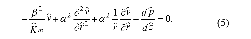
The transport of an incompressible fluid through porous media is given by the Stokes–Brinkman equations, represented in nondimensional cylindrical form by eq 2a and the following momentum conservation equation:
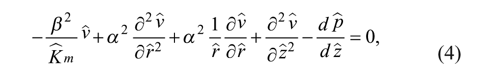
where
The solution to this differential equation is
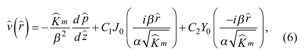
where J0 and Y0 are Bessel functions of the first and second kind, respectively, and C1 and C2 are constant coefficients. Y0 is singular at
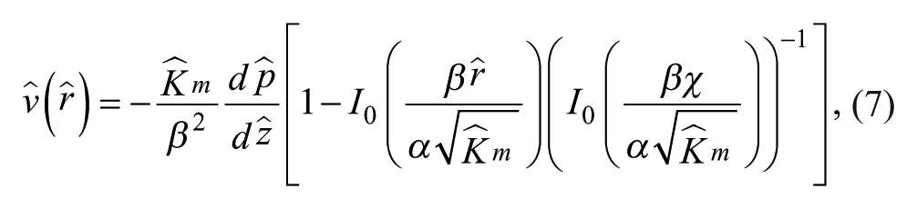
where I0 is the modified Bessel function of the first kind. The bracketed expression approaches 1 for small permeability
We found the ratio of the gripper to part width, χ, to have a small effect on
A critical component that conducts fluid uniformly through its surface, the membrane must be of low permeability for sufficient constriction flow to occur at small ζ. Because χ can also influence the amount of constriction flow, its effect is greatly enhanced when the gripper membrane permeability is increased. Here we examined its direct effect on lift force by simulating gripping at various heights ζ with a membrane with permeability factor κ = 100. With this larger permeability,
Gripper Operation Parameters
We next considered how the operating parameters—namely, flow rate and gripper height—affect gripping. Due to the low Reynolds number that is characteristic of this system, nonlinear terms are comparatively small, leading to the linear eq 2. Thus from eq 3, lift force is proportional to the bulk velocity,
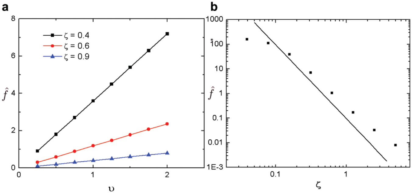
Effects of flow speed υ (
The vertical distance between the gripper membrane and the tissue part, ζ, exerts the greatest influence over the lift force
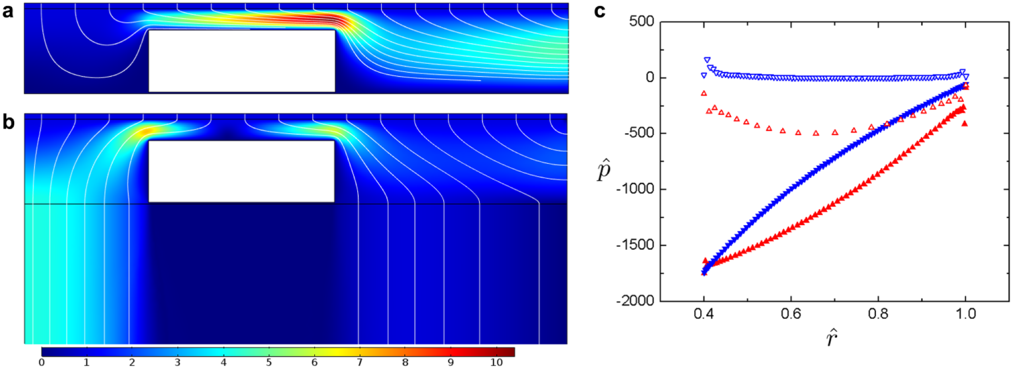
Gripping off solid versus porous substrate. φ = 0.4, ζ = 0.39. Fluid streamlines and velocity magnitude are plotted for SBG (
The pressure along the top surface of the part can be approximately modeled if several simplifying assumptions are made, such as a vanishing radial velocity at the membrane,

along the part surface at
Substrate and Part Properties
Finally, we discuss how properties related to the gripping surface and part geometry can influence normal and shear stresses on the part. The purpose of the gripper is to precisely and gently handle sub-millimeter- to sub-centimeter-scale tissue parts that can be easily deformed when subjected to high-straining flows. The maximum shear rate experienced by the parts during gripping must also be considered and, if possible, minimized. The PBG method aims to address this by allowing both radial and axial entrance flows. Previously, we have limited the discussion to gripping parts on a solid bed. While those results are also applicable to PBG, several key differences arise.
We prescribed the same numerical methods and analysis for PBG as for SBG. Here the part rests on the additional subdomain Ω
b
, which represents a porous platform of height Lb whose void volume is composed of identical, equally spaced cylindrical pores, giving the platform a permeability of Kb = 1.4E-8 m2 along the
Because of the more even distribution of flow, PBG substantially reduces shear stress on the part. Excessive shear forces could adversely affect tissue structure and cell function. When comparing the maximum nondimensional shear rate
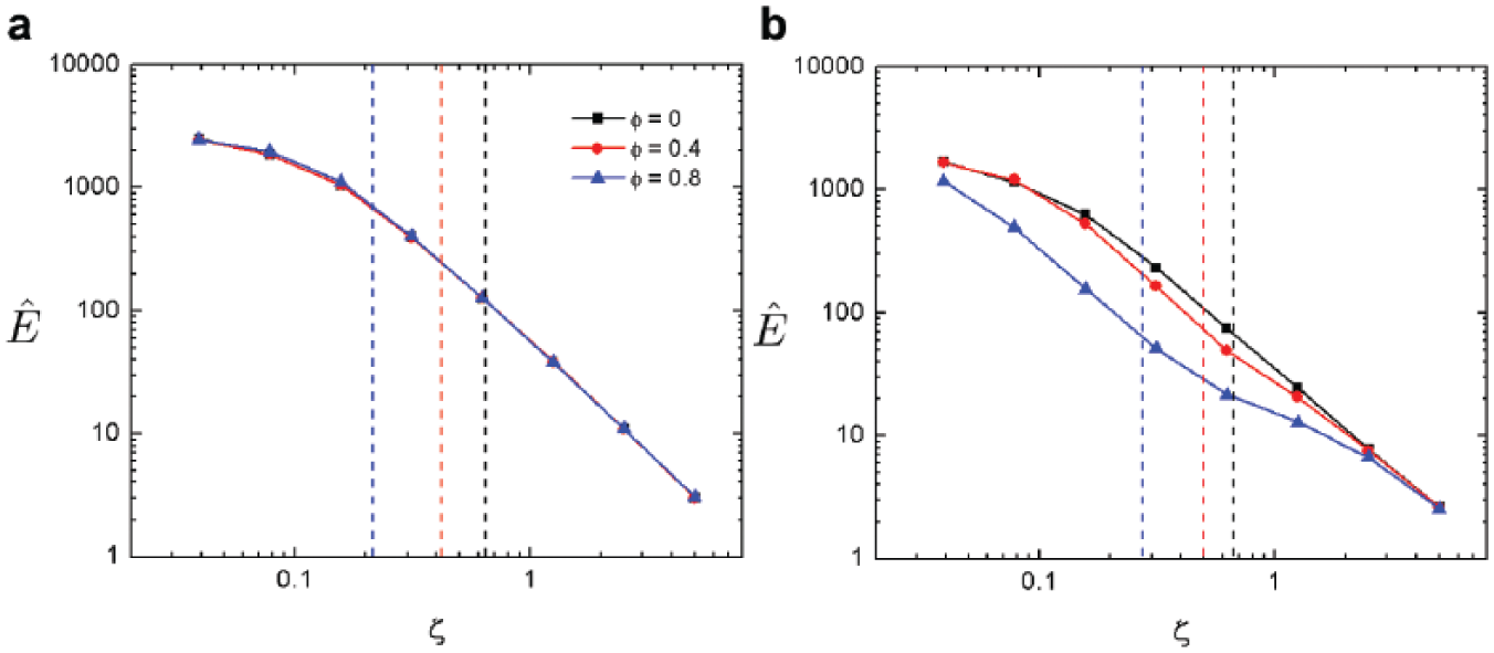
Porous substrate effects lower shear on parts. Maximum shear rate on the part surface is calculated with respect to gripper height for SBG (
It is important to note that the reduction of the maximum shear rate at ζc is not only a result of less straining flows but also due to an upward shift in ζc for PBG, indicating that larger lift forces are generated at a given gripper height. These shifts are presented in
Figure 5
, which details the critical ζ gap width, ζc, with respect to void radius ϕ for both SBG and PBG schemes. From these data, it is evident that PBG elicits greater force per gripper height for toroid parts (and marginally so for ϕ = 0 disks) and thus can lift parts from a greater distance. Furthermore, both gripping methods show similar responses to ϕ; as the void radius increases,
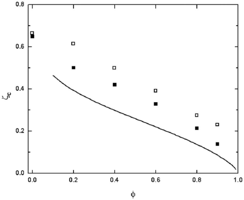
Critical gripper height ζc for void radius φ and spheroids. Filled squares and empty squares represent SBG and PBG data, respectively. Solid line indicates approximated analytical solution for SBG.
We include here a brief description of results for the gripping of spherical tissue parts, or spheroids. Typically 100–200 μm in size, these are by far the most prevalent form of self-aggregated 3D cell cultures currently being studied.
17
Here we consider spheres of 100 μm radius, so that h = 200 μm and ws = 100 μm. Because of the minimized surface-to-volume ratio, spheroids require a low gripper height ζ to be lifted. The velocity and pressure fields generated during both SBG and PBG are similar in nature to those of solid disks. Because they are solid, spheroids do not allow flow to pass through them as with toroids during PBG; nonetheless, a significant increase in ζc was observed for the spheroid using this gripping method (
Fig. 5
). This is due to the ε gap having a short length along the
Because cell spheroids are often nonspherical, we considered spheroids of nonzero oblateness and its effect on lift force
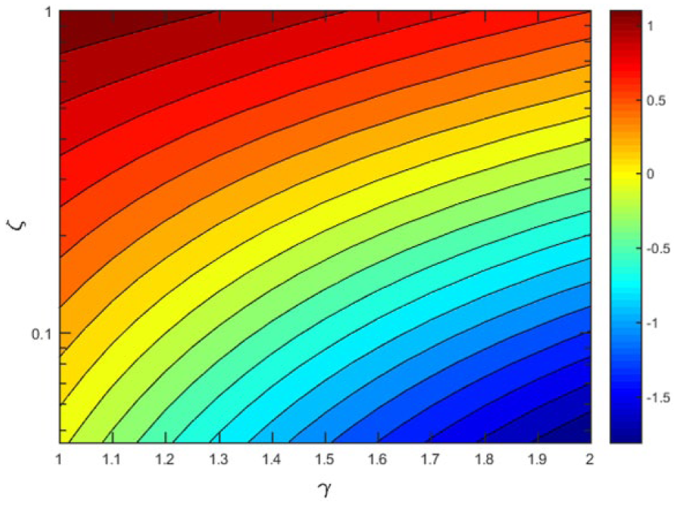
Critical flow speed υc for gripper height ζ and spheroid oblateness γ. The y axis is represented in logarithmic scale. The color scale denotes log (υc). Contour lines denote curves of constant υc.
Lastly, we compared the results of our model to gripping experiments on toroids of various dimensions
8
and on large hepatocyte microtissues. In the former, polystyrene parts of height 0.254 mm and varying width w and inner radius
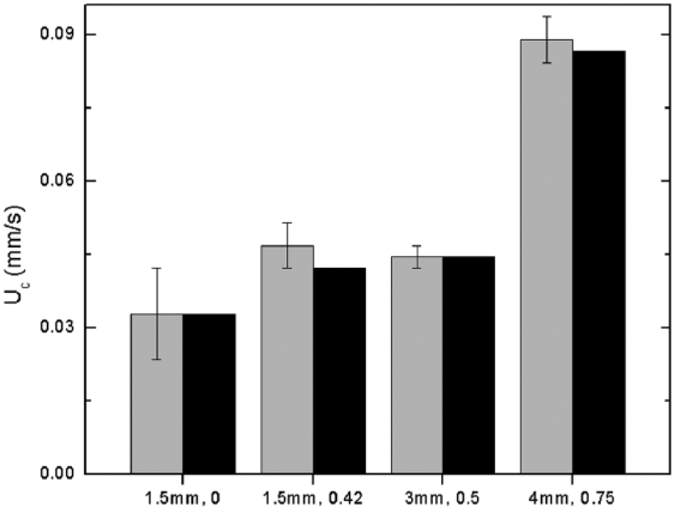
Comparison of experimental (gray) and simulated (black) critical flow speeds for torus geometries labeled by outer radius and φ.
Conclusions
We have investigated the mechanics of gripping using an impinged membrane flow for thin, axisymmetric geometries both with and without a central void. Successful gripping requires a membrane of low permeability, so that sufficient flow is drawn over the surface of the part as the gap between the membrane and part is narrowed. For such low permeabilities, flow is nearly uniform across the surface of the membrane. When parts are gripped off a solid surface, high-straining flow is generated and large shear forces appear across the surface of the parts. For part geometries with voids, PBG is both gentler and more effective, allowing for a more uniform distribution of streamlines along the surface of the part, less radial shear, and more viscous and pressure drag along the axial direction, increasing the hydrodynamic lift force.
Supplemental Material
Supplemental_figures_for_Bio-Gripper_Hydrodynamics_by_Cui,_et_al. – Supplemental material for Hydrodynamics of the Bio-Gripper: A Fluid-Driven “Claw Machine” for Soft Microtissue Translocation
Supplemental material, Supplemental_figures_for_Bio-Gripper_Hydrodynamics_by_Cui,_et_al. for Hydrodynamics of the Bio-Gripper: A Fluid-Driven “Claw Machine” for Soft Microtissue Translocation by Francis R. Cui, Blanche C. Ip, Jeffrey R. Morgan and Anubhav Tripathi in SLAS Technology
Footnotes
Appendix
We evaluate eq 3 by assuming the following: (1) the sum of stresses on the part is primarily composed of contributions from the dynamic pressure, with shear stress being negligible; (2) the pressure is axially invariant unless comparing the top and bottom surfaces of the part, such that
To calculate
where γ is a nondimensional function of
We note that because γ is
For simplicity, we have taken the boundaries of the top flow to be
Returning to eq A2, integrating the right-hand side, and taking
Upon differentiating with respect to
After obtaining an expression for
For parts of disk-shaped geometries (
Subsequent evaluation of the indeterminate terms shows that they approach zero as
Integrating eq A9 and substituting back into eq A7, we are left with the following expression for force generated on a toroid:
This nondimensional force can be converted to the normalized nondimensional force
Acknowledgements
The authors thank J. Murphy III for the fabrication of the Bio-P3 assembly.
Supplementary material is available online with this article.
Declaration of Conflicting Interests
The authors declared the following potential conflicts of interest with respect to the research, authorship, and/or publication of this article: J. Morgan has an equity interest in Microtissues, Inc. This relationship has been reviewed and managed by Brown University in accordance with its conflict of interest policies.
Funding
The authors disclosed receipt of the following financial support for the research, authorship, and/or publication of this article: This study was funded by NSF grant CBET-1428092.
References
Supplementary Material
Please find the following supplemental material available below.
For Open Access articles published under a Creative Commons License, all supplemental material carries the same license as the article it is associated with.
For non-Open Access articles published, all supplemental material carries a non-exclusive license, and permission requests for re-use of supplemental material or any part of supplemental material shall be sent directly to the copyright owner as specified in the copyright notice associated with the article.