
Abstract
Automation of laboratory routines aided by computer software enables high productivity and is the norm nowadays. However, the integration of different instruments made by different suppliers is still difficult, because to accomplish it, the user must have knowledge of electronics and/or low-level programming. An alternative approach is to control different instruments without an electronic connection between them, relying only on their software interface on a computer. This can be achieved through scripting, which is the emulation of user operations (mouse clicks and keyboard inputs) on the computer. The main advantages of this approach are its simplicity, which enables people with minimal knowledge of computer programming to employ it, and its universality, which enables the integration of instruments made by different suppliers, meaning that the user is totally free to choose the devices to be integrated. Therefore, scripting can be a useful, accessible, and economic solution for laboratory automation.
Introduction
Automation is prevalent in most modern laboratories. Automated measurements are more precise, accurate, and economic. In many cases, automated measurements are the only practical way to achieve the necessary results.
Automation can be achieved through autosamplers that can, in some cases, be controlled directly on the measuring instruments. However, more and more the control of measuring instruments and their peripherals is done by means of a computer interface, with software designed for that specific application. In some cases, a single computer controls more than one instrument, and it is possible to control the different instruments in concert if the software was developed for that purpose.
This happens, for example, in continuous-flow isotope ratio mass spectrometry (CF-IRMS): an instrument in which chemical reactions take place (e.g., an elemental analyzer) is connected to a continuous-flow interface, which is subsequently connected to a mass spectrometer. 1 All three are controlled in synchrony by the software provided by the manufacturer. Importantly, all three are also hardware connected, so that signals can be sent from one to the other. If, however, a new method is developed, it may be necessary that another instrument for a different chemical reaction is connected to the system. In this case, the operator will need to make sure not only that the gases coming from the reaction instrument will reach the other parts of the system free of impurities and so on, but also that communication between the new instrument and the system works correctly—otherwise, automation will be compromised. The usual scenario ( Fig. 1a ), in this case, is that the new instrument is able to send or receive instructions from another instrument directly, by means of a cable, for example, and the correct communication protocol needs to be used. In addition, the software employed must be able to recognize the new instrument; otherwise, new software must be written, which is arguably a daunting (or expensive) task. Therefore, this traditional approach limits the instruments that can be used in concert with those able to communicate with others via hardware and also to people with knowledge of communication protocols and/or low-level programming. A way to overcome this last difficulty is the development of a general laboratory automation control system, as proposed recently. 2 However, even in this case, the development of protocols for the software system is a requirement in order that it really becomes universal. 2
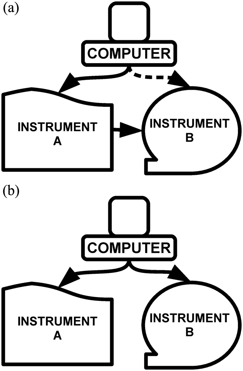
Schematic description of (a) the usual configuration for the integration between two instruments controlled by a computer and (b) a possible configuration when using scripting to integrate two instruments. The dashed line in panel a indicates that the computer control of instrument B is optional, whereas the continuous lines indicate necessary control between two components.
An easier and more general solution can be achieved by means of computer scripting. Computer scripting is the setup of automatic instructions to the computer in order to substitute for user operation. For example, one could write a script stating (in human language), “Repeat this 10 times from now on: Click at position X1, Y1, wait 5 minutes, click at position X2, Y2, wait 13 minutes.” It is clear that if position “X1, Y1” corresponds to one instrument controlled by the computer and “X2, Y2” to another, then these instructions will make two instruments work synchronically, enabling (in this example) the measurement of 10 samples, one each 18 minutes. Notice that the only requirement for this approach to work is that both instruments have each a graphical user interface installed on the computer, which is the norm for the large majority of instruments nowadays, irrespective of the manufacturer. There is no need of a physical connection (cable) between the two instruments ( Fig. 1b ) or of knowledge, by the user, of the communication protocols involved in the process.
Scripting and Laboratory Automation
A script, in computing, is defined as a set of instructions passed to the computer to perform a task. Therefore, a script can be seen as a simple computer program. Scripting has been used in computers for a long time, and there are many different kinds of scripting languages. 3 For laboratory automation, the most useful are those that allow straightforward emulation of user actions, that is, the control of mouse clicks and keyboard operations. The idea is to substitute human operation for an automated procedure, and the most direct way (not necessarily the most computationally efficient; scripting is more about easiness than software efficiency or elegance 3 ) is to simply copy the actions of the software user, which are mainly mouse clicks and, sometimes, text inputs. Control of the timing of these actions is also essential for laboratory automation with scripts. After an action takes place, there is always a time lag due to the operations done by the equipment being controlled by the computer. This time lag must be accounted for when writing the script, including also small differences that may exist from sample to sample (e.g., samples positioned further from the origin of the autosampler could take longer to be reached).
Finally, it is essential that the scripting language enables the user to organize the commands as in structured programming. Structured programming is the prevalent programming technique nowadays, and it enables total control of actions in any imaginable fashion. Readers not familiar with programming techniques can access many resources about structured programming on the Internet.
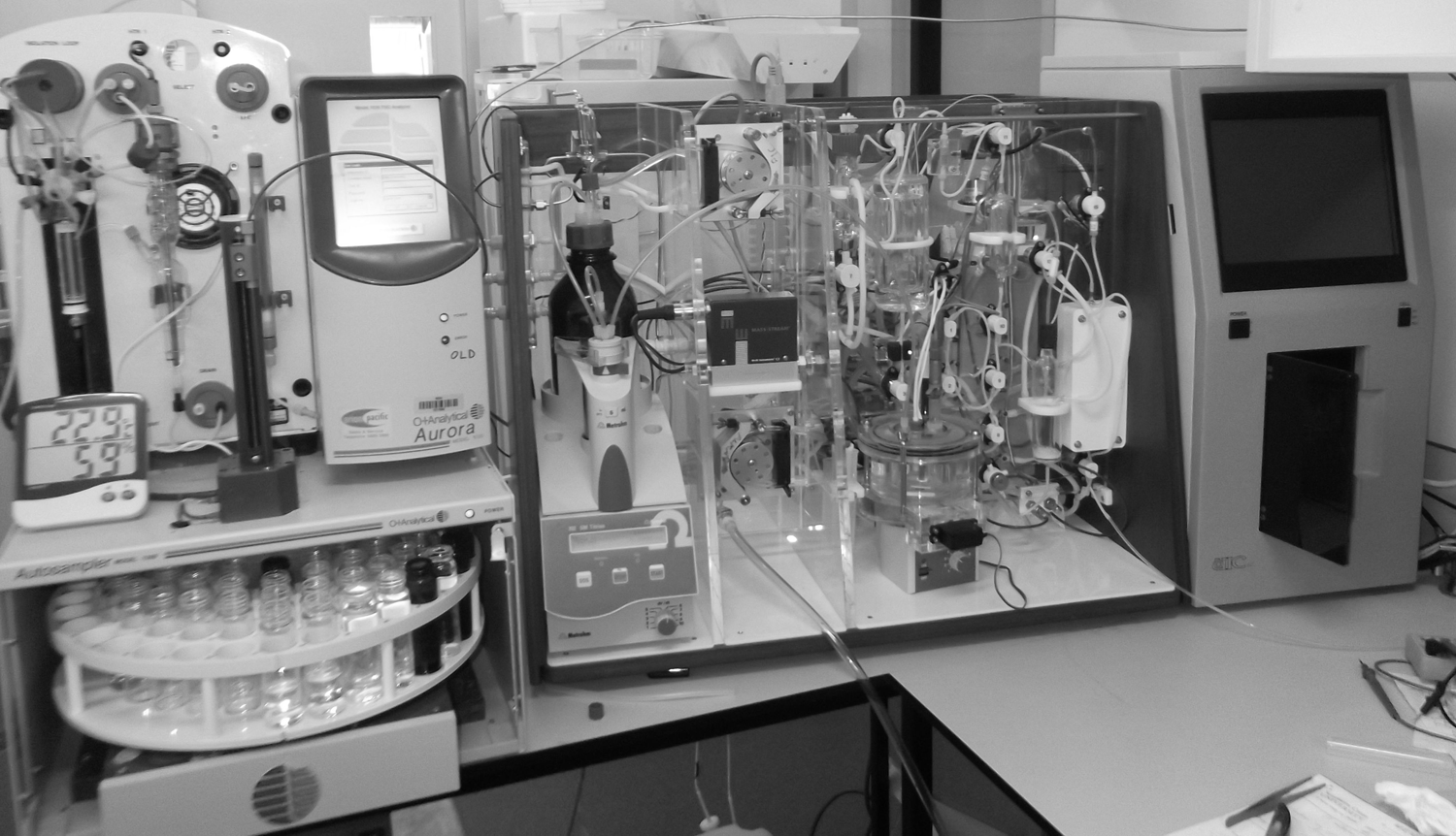
If the scripting language satisfies the criteria outlined above, it can be a very powerful tool in laboratory automation. Compared with other approaches ( Table 1 ), it demands more skills from the user than ordinary computer operation. Nevertheless, it demands much less technical skills than those necessary to write software in the traditional way or to make an electronic controlling device external to the computer. A third alternative is software that allows scheduling of actions, including mouse and keyboard control. However, because these kinds of software do not allow structured programming, they will always be less powerful and flexible than scripting.
Comparison among Different Ways to Integrate Different Instruments in a Laboratory.
A caveat for scripting is its dependence on the software that controls the instrument. If the instrument is controlled by software that does not allow all necessary operations for a given run (e.g., if the software controlling a gas chromatography instrument cannot configure the temperature ramp), scripting utility can be limited.
Integration of Analytical Instruments: An Example and Short Tutorial
Scripting power for laboratory automation can be demonstrated by the ability of integrating different analytical instruments without need for an electronic connection between them. Such an approach in theory enables the integration of any kind of device, as long as the software has graphical user interfaces. An example will be presented below.
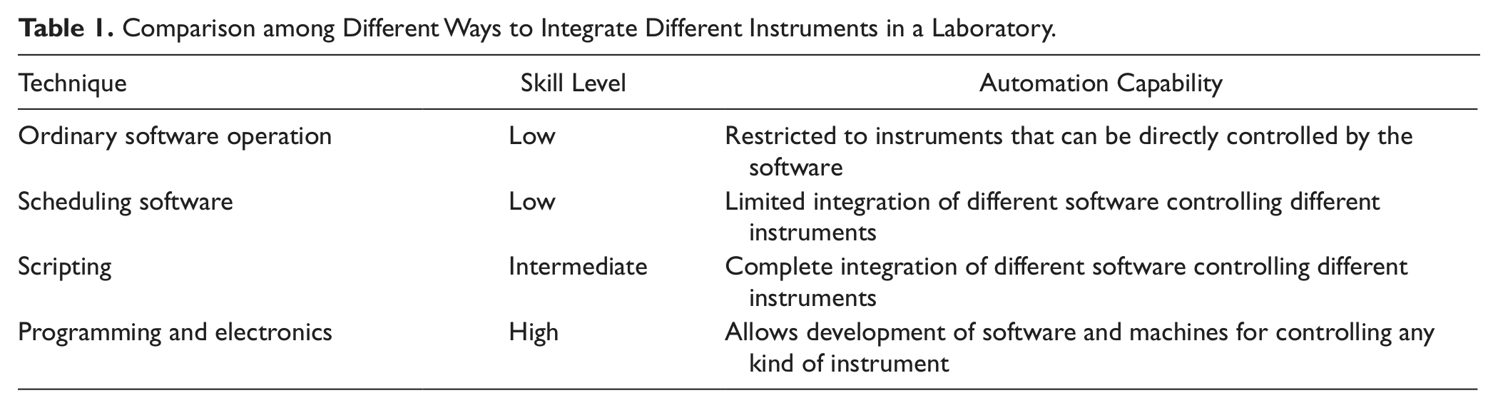
In our laboratory, we successfully employed AutoIt (www.autoitscript.com), a free, open-source scripting language for the Windows Operating system (chosen based on the author’s experience; other languages with similar capability are available), to synchronize the autosampler of a total organic carbon (TOC) analyzer, Aurora 1030w (OI Scientific, College Station, Texas), and a system developed to measure dissolved inorganic carbon (DIC) in water samples by coulometry, the VINDTA 3C (Marianda, Kiel, Germany) ( Fig. 2 ). The motivation was that the precision of the VINDTA for DIC measurement is 0.1%, which is the best available nowadays, but the instrument does not have an autosampler. Automation of this measurement would be very convenient, for example, for determination of photosynthesis and respiration in water. 4
Instrument configuration. Left: Aurora 1030; only its autosampler is used. Center: sample handling part of the VINDTA. Right: VINDTA coulometer for CO2 detection.
The physical coupling of the two instruments was very simple: The sampling line of the VINDTA, a ⅛-inch Teflon tube, was connected to the sampling needle of the autosampler of the Aurora. This way, the water from vials on the Aurora autosampler could be collected straight to the VINDTA. No wire to send signals was used to connect the two instruments.
The VINDTA needs about 60 mL of water for DIC measurement, and the autosampler in the Aurora can only handle 40-mL vials. Thus, each measurement needed to sample two vials each time. The VINDTA software has a function that allows the division of the sampling in two steps, and this was applied. Manual testing was done to determine the timing of each operation.
If everything had to be done manually, the operator would go to the Aurora interface ( Fig. 3 ) and click on “Vial #,” type “1”; then click on “Move to Sample Vial”; wait until the autosampler is at the correct position, then click on “Depth(%), type “100”; and finally click on “Move to Needle Depth.” Then would come the VINDTA operation ( Fig. 4 ): The operator would click on “Other,” choose the “DIC.mth” method, and click on “Open.” If the sample vial were big enough, this would be all. But since this is not the case, the operator would monitor the VINDTA operation and, after the rinsing had finished, the operator would again use the Aurora interface, this time to move the sample to the next vial containing the sample that would really be measured. As explained before, the VINDTA was configured to allow this vial exchange. The last step would be to wait until the measurement is done and to start everything again for the next sample.
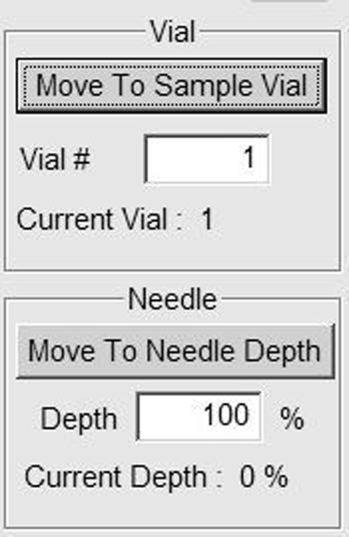
Graphical user interface for the Aurora autosampler.
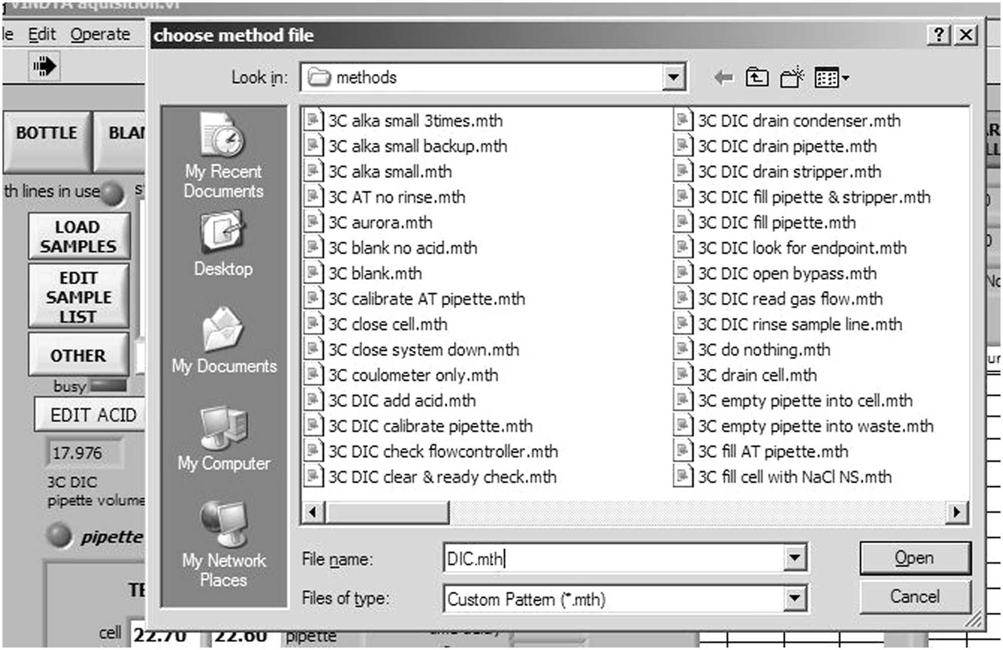
Graphical user interface for the VINDTA.
Writing a script to control both instruments consists of translating the above paragraph to a language that the computer controlling both the Aurora and the VINDTA can understand. The instructions in AuotIt language are in Figure 5 . AutoIt language is very similar to Basic, and readers familiar with this language will have no problem understanding the code. However, to make it accessible to the other readers, an explanation about the components of the code will be given, so they can modify it according to their needs. Before that, the interested reader must download and install AutoIt.
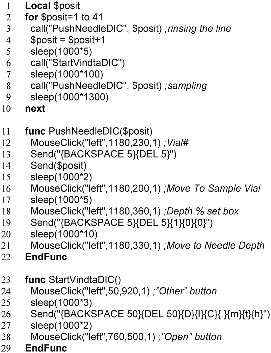
AutoIt code for measuring 21 samples using the autosampler of the Aurora with the VINDTA.
The code is divided in three sections. The first part (lines 1–10) is the main body of the code; the other two parts (lines 11–22 and 23–29) are “functions,” that is, blocks of code that are called in the main body to avoid redundancy, thus making the code easier to follow.
Line 1 in Figure 5 declares the single variable in this code, the variable “$posit.” Declaring variables is not essential in AutoIt but is good programming practice. Line 2 is the start of a loop, which is closed in line 10. The loop says here to do everything in lines 3 to 9 until the variable $posit reaches the value of 41 or higher. It will automatically increment $posit value by 1 every loop. In the loop, the functions declared in the other parts of the code are called three times: lines 3, 6, and 9. Notice that the function “PushNeedleDIC” needs an argument, which in this case is the variable $posit. In line 4, $posit is incremented in 1 unit. This is done so that the autosampler will go to the next vial in the sequence before it samples again. Notice that because of that, the loop that goes from 1 to 41 measures 21 samples, because $posit will be incremented by 2 units each loop. In lines 7 and 9 is the command “sleep.” This command tells the computer to wait a given number of milliseconds until the next action. The values input here must be determined based on the observation of the instruments working during the measurement.
The function “PushNeedleDIC” is defined in lines 11 to 22. In lines 12, 16, 18, and 21 is the command “MouseClick,” which uses as arguments the mouse button to be clicked (left), the X position, the Y position, and the number of clicks (1). Lines 13, 14, and 19 contain the command “Send,” which is a keyboard emulator. In line 14, “Send” tells the computer to type the variable $posit. In line 13, the command tells the computer to click the keys “backspace” and “delete” five times each, so that it is ensured that the writing field will be empty. In line 19, besides these two actions, the computer is also instructed to type “100.” The function “StartVindtaDIC” in lines 23 to 29 can be understood with the explanation given for “PushNeedleDIC.”
It is important to notice that the positions for the mouse clicks ( Figs. 3 and 4 ) must be kept static on the screen so that the script ( Fig. 5 ) works properly. Also, no other software window can be maximized on the screen. Therefore, when the script is running, it is essential that computer operation is relegated solely for this purpose. AutoIt enables features like making sure that the windows are at the right position every time before a mouse click (“WinMove” command) and that the keyboard and mouse are locked until the script is finished (“BlockInput” command), but these were not included in the example because they are optional. Readers interested in learning more about AutoIt can find plenty of information on the Internet.
Using the procedure described above, precision of 0.08% was obtained for unattended DIC measurements of 13 replications of a sample (tap water enriched in bicarbonate). Another script was written, using the same hardware, but this time for alkalinity measurements. Precision of 0.14% was obtained for unattended measurements of 11 replications of the same sample used in the other test.
In conclusion, scripting can be a powerful way to enable and enhance laboratory automation and is especially suitable for integrating and synchronizing instruments without need of a physical electronic connection between them. This means that users are free to choose the instruments they want to integrate, regardless of specifications determined by the suppliers of the instruments. Therefore, integration by scripting can be an economic solution: In the example given here, the buying of a new autosampler (or, alternatively, the use of many hours of a technician) was avoided, without compromising the quality of the results.
Another important aspect of scripting is that it is more accessible than low-level programming and electronics, which are the traditional techniques to integrate instruments. In other words, less time and money can be spent to achieve similar results.
Footnotes
Declaration of Conflicting Interests
The author declared no potential conflicts of interest with respect to the research, authorship, and/or publication of this article.
Funding
The author disclosed receipt of the following financial support for the research, authorship, and/or publication of this article: Financial support was received from Southern Cross University, including salary and access and use of necessary laboratory equipment and reagents necessary for the experiments described.