
Abstract
An exoskeleton is an external cast which can be used to maneuver, protect or even provide a greater magnitude of strength to the upper limb allowing for heightened efficiency and performance. The limb may be weakened due to so many diseases or reasons such as paralysis, stroke, muscular atrophy, and different kinds of injuries. Numerous designs and manufactured prototypes of pneumatic exoskeletons have been reviewed—their pros and cons weighed against each other. This paper covers the fundamental concepts of various prototypes that have been designed and developed over the years. The best mechanism has been highlighted, although the design of a fully efficient exoskeleton comes with its set of drawbacks. Types of energy used for the driver unit, types of actuators, materials used, design concepts, and overall weight and manufacturing cost of every prototype has been contrasted with the others to conclude what an ideal exoskeleton for rehabilitation purposes must look like and the principles and features of the prototype must be decided upon by keeping aesthetics and ergonomics in mind.
Introduction
Pneumatic systems use compressed air as the driver unit for actuating the mechanism of the exoskeleton. The exoskeleton must be designed keeping all the necessary factors in mind including—the aesthetics of the entire model, usability, user-friendliness, durability, manufacturing cost, portability, easy maintenance, and enhanced efficiency. It is an external mechanism to aid the movement of the upper limb as well as provide it with the power it lacks. This exoskeleton must not weigh down the limb or worsen the condition of the limb due to defects in the design.
This paper covers the fundamental concepts of various prototypes that have been designed over the years. On reflecting upon the history of the first pneumatic exoskeleton, the latest inventions show a great deal of progress and have quite successfully managed to eradicate a significant number of drawbacks. Pneumatics are ideally preferred as the energy input for the actuator due to their less weight and the circuit being easy to design.
Each prototype differs as per their energy input and actuation methods but the fundamental design and applications have stayed the same. Recent innovations have explored the idea of a wearable pneumatic sleeve that is easier on an injured or paralyzed limb. This idea could go a long way as it is comfortable, convenient, and moves forward from rudimentary mechanisms, and can be worn for longer periods of time. These designs are supposed to be an aid to the patient and not an ailment, thus a lot of thought has gone behind finalizing each and every design—each design more progressive than the former.
Literature review
A wide range of publications based on pneumatic exoskeletons for upper limbs for the purpose of rehabilitation or to allow the limb to perform actions it is inhibited from- were reviewed. Their concept, principle, mode of actuation, design mechanism, advantages, limitations, and applications were carefully considered.
For instance, Morales et al. 1 conducted an in-depth research about the types of pneumatic rehabilitation devices made and about what kinds of robotic systems have been designed. They also wrote about the case study conducted at Miguel Hernandez University for delivering PNF treatments to patients in supine positions. Focusing mainly on the types of robotic exoskeleton systems and their characteristic features. These are the number of degrees of freedom (DoFs) allowed and the comfort measure of the grasping points. They concisely and comprehensively summarized their findings of four such types of robotic devices.
Mechanism design
There is a broad spectrum of mechanisms that have been designed for the functionality of the pneumatic exoskeleton for rehabilitative purposes. The mechanism design determines the complexity of the system and provides an accurate estimate of the weight, maintenance required, and portability of the device.
In the work of Shen et al., 2 their exoskeletal framework consists of a human upper extremity having seven DoFs: shoulder extension, shoulder adduction, shoulder rotation, elbow extension/flexion, forearm pronation/supination, wrist extension/flexion, and wrist radial/ulnar deviation. An exoskeleton's DoFs can be used to define structures. The number of arms available is also important since more movement protocols can be used if there are more arms available (e.g. mirror-image symmetric training). The location of the human-machine interface is also something to think about.
On the other hand, the work of Xu et al. 3 describes a mechanism where the foundation is a wheeled frame that is used to transport items and support the motion system and the adjustment unit. The most critical aspect of this is the motion module. Between the foundation and the motion, mechanism is where the adjustment module is located.
On exploring the plausibility of a soft and wearable pneumatic exoskeleton, Li et al., 4 came up with a trademarked prototype called “Playskin Air” which depicts the modeled prototype exoskeleton which can assist a child of 11 years of age to be able to lift and drop down his arm as he wishes via the usage of an air bladder which fits like a cuff around the user’s arm and can be inflated and deflated as required by a solenoid valve. On inflation of this cuff, the sleeve will tend to move the arm up and down when inflated and deflated, respectively. Inflation and Deflection mechanism: Inflation was considered using three different concepts: (1) self-inflation from exhalation, (2) electric air pump, and (3) compressed CO2 cartridges. After a short period of research, it was discovered that the self-inflation technique was difficult, sluggish, and prevented users from conversing. There were two major flaws with electric air pumps when in use, the total weight and noise. The compressed CO2 cartridge (cycling deal and model: threaded 16 g) was attached to a pressure regulator (MR brew and model: Mini CO2 regulator with 3/8 thread) in the final prototype, and then two solenoid valves (Plum Garden and model: 14 DV 12 V 2 way normally closed electric solenoid air valve) were used to regulate the gas release (Figure 1).
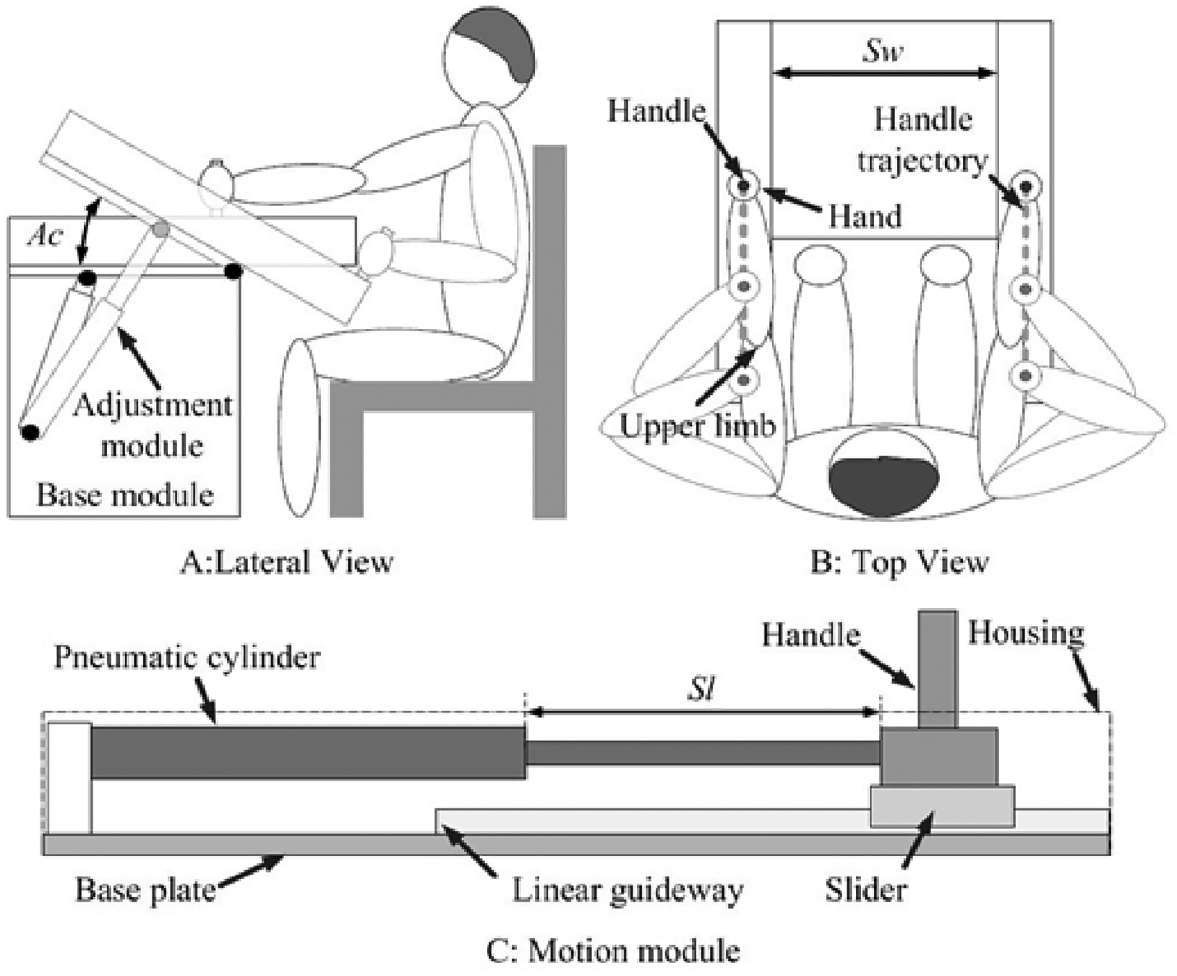
The mechanism design utilizes a wheeled frame and motion module. 3
However, there are significant drawbacks to this design as the air bladder cannot be completely leak-proof throughout the life cycle of the product and secondly, this apparatus cannot be worn with ease and no discomfort as for the system’s functioning, the bladder tightens around the arm and also presses down it. Thus, even though the circuit works, it cannot be worn for longer periods of time. Another consideration is that the solenoid valve could fail, thus rendering the apparatus dysfunctional and even if it does not—the time period needed to inflate and deflate the bladder could hinder productivity.
Similar to this concept, another wearable pneumatic exoskeleton was designed- except for the hand instead. This prototype makes use of “pneumatic artificial muscles” which are usually constructed and made as a latex or rubber tube with a weave sleeve. Fiber coating protects the rubber tube, and both ends are fitted with appropriate plastic or metal fittings. PAMs transform pneumatic strength into pulling/pushing force and have several advantages. This mechanism also makes use of a solenoid valve and a controller system. 5 The soft exoskeleton is made up of curved extender and contraction artificial muscles.
The exoskeleton is designed to suit any adult without requiring mechanical changes. Both wrist recovery movements are possible with the exoskeleton. The mean force of the wrist flexion motion is ∼37 N, which is the total of the two extended bending muscles. The production force in all other movements is the same since they all use the same contraction muscles, and the maximum force is about 55 N. The in-depth investigation of the work of Ferguson et al., 6 the mechanism details of the hand exoskeleton: The most direct way to allow hand exoskeleton motion to influence DOFs of the hand predictably is to align the exoskeleton joint's axis of rotation with that of the human joint, as seen. Exoskeletons with matched axes are referred to as matched axes exoskeletons in this context. Another option is for the exoskeleton's mechanism to cause each connection to rotate around remote centers of motion associated with the finger joints, as shown. There are many methods that could be used to do this, and the issue has been investigated. Popular mechanisms in this group for hand exoskeletons include parallelogram mechanisms and circular-prismatic joints. Depending on the design, these mechanisms can be low-profile.
Some prototypes have been designed as per the naturally occurring shoulder motions over a wide range of motion, as well as force and impedance control. This prototype, known as “Harmony” 7 makes use of synchronized shoulder motions for its functioning. The shoulder design for the mechanism has been delineated: Elevation–depression, protraction–retraction, and anterior–posterior axial rotations are all part of the clavicle’s pivot motion, or SC motion. The functionality of anterior–posterior axial rotation of the clavicle can be safely overlooked during the design of the shoulder girdle system since it widens the range of motion of the GH joint.
The system design entails the shoulder girdle design, ball and socket design, forearm design, and final kinematic design and alignment. Harmony uses the SEA device and this paper goes on to talk about the mathematical modeling of SEA, its dynamics, and how it applies to the entire mechanism. The expected outcome of this prototype is that Harmony’s dynamic and kinematic characteristics will permit the development of new exercises, therapeutic in nature with a broad range of 3D body movements and dynamic interactions, potentially improving robotic rehabilitation efficacy (Figure 2).
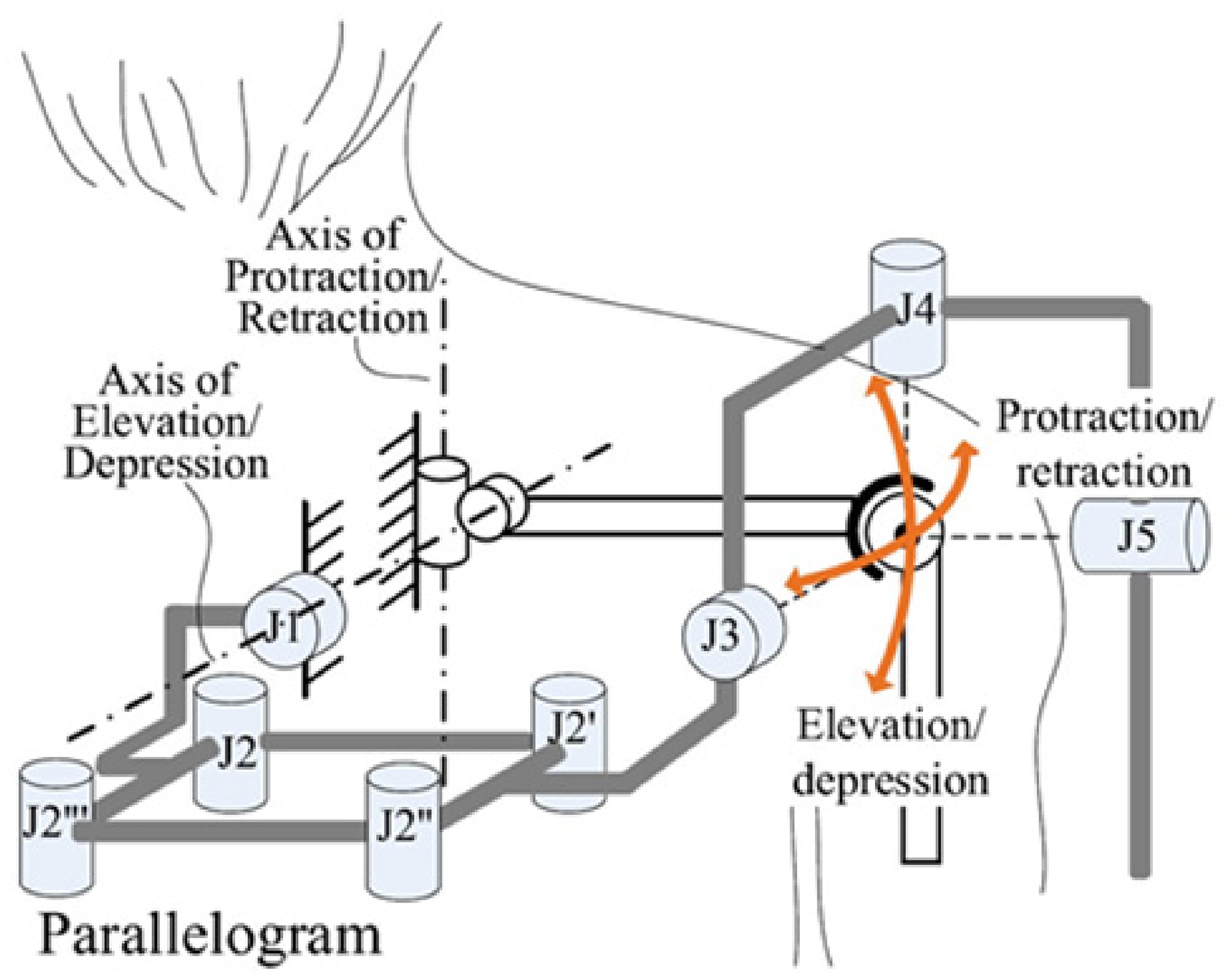
Diagrammatic representation of shoulder girdle mechanism. 7
In further developments of such prototypes, the work of Rahman et al.8,9 talks about the production, design and control of the ETS-MARSE. The design entails the shoulder joint motion support portion—it has two motors and two connections (two links: A, B), and two potentiometers to help with horizontal and vertical flexion motion. Link-A is rigidly constrained to the robot’s base structure at one end and carries motor-1 at the other. It is noted that Link-B is bolted to motor-1 and carries motor-2 on its end. The ETS-MARSE is made up of an arm chain, a sliding link (C), a fixed link (D), a motor, a tailored open-type bearing, a ring gear, a backlash preventive gear, and a potentiometer that helps with the rotation of the shoulder joint.
Elbow and forearm motion support: A forearm arm connection, fixed link (D), along with a motor and potentiometer which make up the elbow motion support portion. Even though the ETS-ROM MARSE for shoulder joint internal and external rotation ranges from 70° to −85°, it can be adjusted to any value within that interval, such as 45° to −45° or 40° to −70°. The ETS-MARSE is regulated by a user-input wrist force sensor command in the active recovery technique to assist or guide the subject in performing specific tasks such as gripping or grasping.
For attaining the required torque for the movement of the exoskeleton, there can be several mechanical approaches such as using a ball screw mechanism and using a pulley with cables. 10 The necessity to design a full exoskeleton, including the shoulder joint structure, that could be mounted on the backrest of a chair led to the first version of ABLE 4D which included two SCS modules in the humerus limb, each controlling a transverse axis. The absence of a bevel gear has clear volume and mass advantages in this configuration. The SCS’s effective incorporation in the ABLE design framework of the exoskeleton demonstrates how an adaptive element works in tandem with a rigid mechanical segment to guarantee a low and, most importantly, repeatable degree of friction inside a light and moderately deformable host structure.
On observing the rapidly advancing prototypes with their various and unique mechanisms, the idea of constructing a soft, wearable, and portable exoskeleton was pondered upon. The innovation involved in the design concept that satiated these needs was that this exoskeleton could be tailor made to the user’s arm. 11 The average maximum error in this analysis was 3.16 mm (standard deviation 1.47 mm), Given the lax couplings between the exoskeleton and the hand fingers and the relative sliding between skin and bones, this was deemed sufficient. Finally, a 3D printed Acrylonitrile butadiene styrene prototype—optimized on the patient’s hand size—was been manufactured and tested. The recent experiments of this prototype also showed the effectiveness of the mechanical design improvements in improving system portability. The elimination of the distal thimble, the inclusion of the passive DOF, and the incorporation of active control over the ROM have freed the user from unpleasant feelings of duress and insecurity (Figure 3).
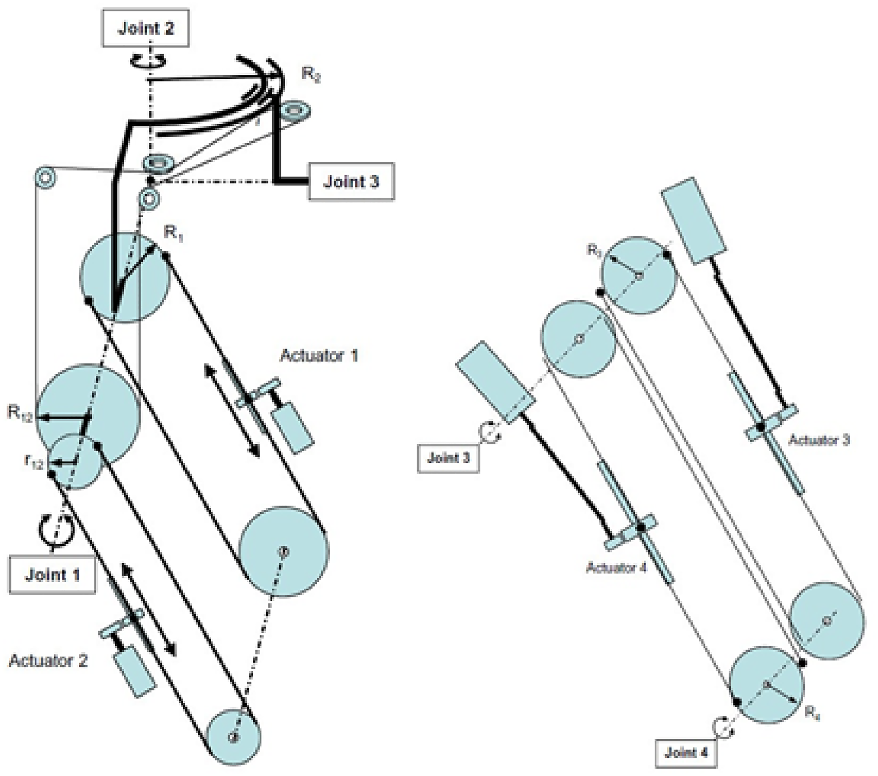
The mechanism of the ABLE 4D. 10
To further develop a prototype which provides an unconstrained, regulated upper-body exoskeleton for use in rehabilitation and regenerative medicine, as well as occupations that require enhanced strength, a prototype actuated via a DC motor was generated.12,13
The DC motor that is necessary to raise the load is chosen. The DC motor is set to lift the load to a specific height. The back panel, which is worn as a backpack, is attached to the DC motor. The backplate is connected to the forearm by a series of connections. The motor shaft is attached to a circular drive. The circular drive and a pulley that rotates the forearm are connected by a cable. The pulley and the forearm both rotate while the drive rotates with the engine. A PIC microcontroller controls the rotation of the motor (PIC16F877A).
Lightweight exoskeletons with load augmentation characteristics too could be implemented in rehabilitative and therapeutic treatments. Derived from the work of Walsh et al., 14 the actuator of the exoskeleton is driven by wires which decreases the actuation system’s weight on the patient. The forearm rotational design system ties to the forearm through a brace. The brace is made to fit snugly around the user’s arm and has attachment points for the mechanism. The elbow joint is designed to provide free mobility in order to allow for realistic motion. A compact base unit with series elastic actuators and an electric motor powers the drive mechanism. The force on the cables is calculated using the load cells in the base unit. A pair of angle sensors, one on the power source and the other on the arm actuator, provide location feedback to the control unit. The control system’s use of “series elastic” components in the drive is a unique feature. The elastic actuators have the advantage of being mechanically compatible even when the consumer makes abrupt torque inputs. The elastic actuators’ spring constants are determined by the maximum forces needed for rehabilitation. The control loop has been set up to attain the right outcome. The dynamic response is obtained by feeding the computed torque back into the device, which drives the forearm's angle of rotation. This technique is comparable to pneumatic actuators were used in the system mentioned in used to switch the weapons the measured torque is converted into a number on the basis of sensor inputs.
The concept of an arm exoskeleton with scapula motion was proposed as part of an inquiry conducted upon the emergence of an arm exoskeleton framework for treating shoulder pathology. 14 In this design, the admittance controller is used to manage the scapula joint separately from the arm joints. The torque exerted by the scapula joint is directly measured by a torque cell at the transmission’s output. However, a gravitational model is used because the applied torque must match the sum of the gravitational torque and the torque applied by the subject.
After exploring the various possibilities of innovations in pneumatic exoskeletons, some authors like Klein et al., 15 drew inspiration from biochemical processes and came up with a design that exhibits the use of synthetic materials to replicate these processes. This prototype was called “Bones” an acronym for “biomimetic orthosis for the neurorehabilitation of the elbow and shoulder.” The design of Bones is such that the arm exoskeleton simulates upper arm motion by rotating around the shoulder as a spherical joint. The humerus bone of the subject is rotated in flexion around the x-axis (S to E). At point E, the x-axis of the upper arm coincides with the elbow joint. The dimensions of the upper arms (LH) can be modified to suit a broad range of subjects. The arm at the elbow is actuated by two rods that can slide without providing any resistance. One rod acts as the pivot around a static point YT (the top yoke’s center of rotation, that is connected to the actuators). At point TEC, it is connected to the actuators and linked to the arm exoskeleton. The exoskeleton (including the elbow actuator) weighs 3438 g. For a total arm weight of ∼4360, the arm exoskeleton module weighs 921 g. A human upper arm weighs ∼2500 g, while a human forearm weighs 1720 g, for a combined weight of 4220 g. As a result, the exoskeletal sections that the subject must pass have a mass equal to that of a human arm.
Actuation and control
There are four types of actuation commonly used in various prototypes of exoskeletons:
Electric motors: Numerous braces utilize this type of actuator to accomplish high control accuracy and quick reaction. Based on the number of active DoFs, a study of current upper limb exoskeleton systems shows a compromise in either power input or portability. The high cost of installing an electric actuator is another drawback. Pneumatic actuators: Using a pneumatic actuator could save a lot of burdens while still creating a great deal of circulatory force but it adds more complications and difficulties to the regulator’s design. Proportional regulators and valves are needed, but they come at a higher cost and with more complexity. Hefty pumps and compressed gas cylinders can reduce the system’s portability, contaminate the oil/lubricant, and increase downtime and maintenance. Hydraulic actuators: Hydraulic actuators may be able to meet the need for increased torque output, especially to supplement human capability. Comparable to pneumatic actuators, control is less precise than electric motors, and incompressible liquid from a pump can contaminate the entire system, jeopardizing protection. Thanks to devices like a fluid tank, generators, pumps, valves, heat exchangers, and noise-reduction equipment, this form of the actuator is better suited to human capacity augmentation than providing assistance or robotic physiotherapy to aged individuals and patients. Series elastic actuators: They’re recognized for their force control stability strengths. and pHRI protection. To attain a particular level of enforcement, there are many approaches: to change the rigidity of the transmission systems and the physical connections connecting the actuator to the end effector, as well as the energy storage capacity of the transmission/linkage pair.
Most of the prototypes use pneumatic actuators due to their lightweight and higher torque yielding capacity. Xu et al.
3
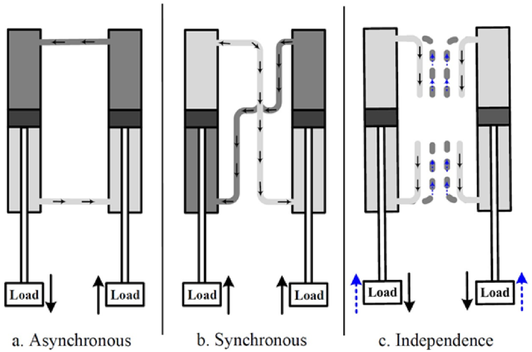
used a pneumatic system in their prototype. In this system, the bilateral robotic system’s variable resistance can be modified depending on the severity of the patient's impairment. Two pneumatic cylinders are used in the motion module, each with its own airflow. Variable resistance results from modification. This research makes use of various variations of throttle valves for various airflow regulations. In joint asynchronous movement mode 1, the electromagnetic valves e1 and e4 in the mode switching unit are open, the four throttle valve groups are closed, the cylinder’s two rodless chambers are linked to each other, and the two rod chambers are linked in the same way. When one human arm moves the handle, the other pulls, causing the inner air of the cylinder to flow to the attached chamber. Mode (b) is similar to mode (a), but the handles go in the same direction (Figure 4).
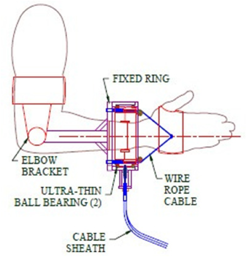
Depiction of installation of the mechanism on the upper arm. 14
The throttle valve groups are programmed as per the required functioning and Three one-way throttle valves regulate airflow in each throttle valve group. To achieve different flow configurations, the position of the valve spool is set according to its flow characteristic curve, ranging from valve x1 − 15 L/min, x2 – 30 L/min, etc. The various combinations used are displayed below (Figure 5):
Pneumatic system working depicted. 3
The average flow is around 208 L/min when all valves are closed and 0 L/min when all valves are open. Since the throttle effect is less noticeable at higher flow rates, only levels 1, 4, 6, 7, and 8 in column A are used for resistance alteration, and they are reassigned as levels 1–5 in the first column. Many prototypes use these kinds of actuators whereas some prototypes like the “Playskin Air” uses an air bladder with a solenoid valve inlet for its actuation method. Allowing for innovation in the actuation mechanism, Wolbrecht et al. 16 put forth the utilization of a controller to provide the required sensing for effective pneumatic regulation.
This controller specifies force commands for the previous section’s low-level force controller. As a result, the robot employs an outer loop that issues high-level instructions to the force control system’s inner loop. To convert cylinder forces to task space forces, Jacobian matrices extracted are used (Figure 6).
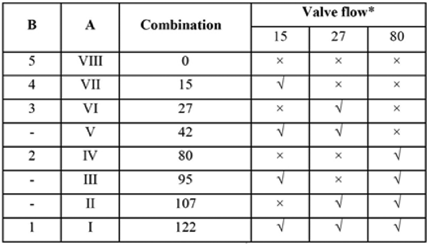
Table displaying different throttle valve combinations. 3
Kinematics and analysis
The kinematics of a designed prototype dictate its future scope and allowance of modifications. For instance, in the tailor-made wearable exoskeleton. The discussed model will serve as the mathematical foundation for modifying the exoskeleton to conform to various finger paths. Nevertheless, before delving into the kinematics, a brief explanation of the definition of the hand exoskeleton under consideration is required. The prototype’s assembly is thought to be made up of two simple modules: the “finger mechanism,” which is a planar mechanism that is positioned over a finger, has a single DOF, and is responsible for actuating the finger’s extension movement; and the “back case,” which is a rectangular mechanism that is mounted behind the finger. Elaborating on the concept of a Hand exoskeleton, 17 the optimization approach that combines kinematic efficiency as computed by uniformly directional mechanism and the size of the mechanism is determined by the planar area occupied between the mechanism and the digit.
This method contributes to an examination of often-overlooked aspects of hand exoskeleton manipulator optimization. It starts by outlining templates for the mechanism as well as the related digits. Second, an equation is given with a brute force algorithm that scores each potential mechanism based on a predefined Design Ranking, with the goal of managing a wide range of hand sizes with fixed link lengths and achieving the best kinematic performance inside the workspace. As a result, the thumb, pointer, and ring finger optimization algorithm results are displayed. For the predefined constraints, such as the predetermined positions of the 3R mechanisms’ foundation, it also displays the ideal connection lengths as well as the Design Score associated with them.
Thus, it is observed that Kinematics and simulation analysis play an important role in determining the areas for improvement and refining the prototype (Figure 7).
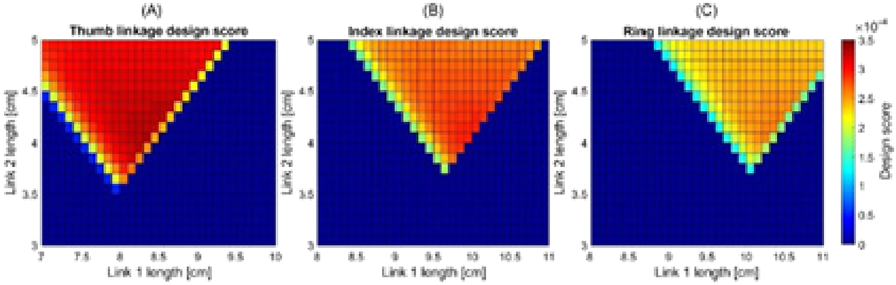
Simulation results of kinematic analysis of hand exoskeleton. 17
Advantages and limitations
As thorough as these mechanisms are, they aren’t entirely foolproof. Despite being backed up by experimental research, credible evidence, and concrete principles, these prototypes still have significant drawbacks. When these drawbacks are countered through automation, robotic devices, and complex variants, new drawbacks arise from the limitations of these counter mechanisms. With respect to this, Gorgey’s 18 work focuses on delineating these advantages and limitations. It identifies two key areas related to exoskeleton design and implementation on significant health implications following SCI. Safety concerns, exoskeletal brace fitting time, and the exoskeletal brace pace are all addressed from a design standpoint.
The wellness viewpoint includes bone health, body weight, physical activities, and pressure injuries, Clinical studies have been being conducted to correct some of these flaws and optimize the benefits in recovery environments. Future directions emphasize the use of exoskeletons in conjunction with other existing and emerging technologies, such as brain-computer interface and functional electrical stimulation, to address severe limitations. Exoskeletal braces have the potential to revolutionize Spinal Cord Injury therapy; however, it is still too early to make firm recommendations on their clinical use. To begin walking with a stick, to control the assistive device, to assist bodyweight shifting, as well as providing balance while standing, it is essential to have reasonable hand functionality. To solve this problem and provide safe accessibility to a large segment of the Spinal Cord Injury population, proactive ways of using walking sticks or other equipment are needed.
Extreme precision is required when drawing broad conclusions about exoskeleton-assisted rehabilitation. Analogously, while academics are beginning to recognize exoskeleton sensors as a significant source of information for assessing patient health, it is critical to emphasize that conventional exoskeletons’ capability to provide accurate information of human motion quality is proportional to their ability to be clear.
One of the performance metrics for an exoskeleton is its clarity, which measures its ability to precisely produce programmed assistance to the subject. Transparency tests the robot's ability to move freely without assistance or opposition, which may seem to be contradictory. 19 This property, on the other hand, is a reliable predictor of force precision. Transparency thus qualifies the structure's mechanical properties (mass, friction, inertia, etc.), its driver unit that actuates the mechanism (back-drive-ability, friction, etc.), and the minor control's efficiency in order to compensate for these disturbing occurrences (feedforward compensation of the friction and gravity, for instance.) A deficit in clarity can produce unwanted strains. When subjects move their upper limbs, from which greater muscle activities can arise to complete even elementary movements. Evidently, this can be insignificant for salubrious people despite being extremely agitating to patients.
Gap analysis
Although each and every prototype covers all the failure aspects of the former designs, there are still multiple drawbacks in every new model. These drawbacks have been worked on as much as possible; still, there is always scope for improvement in the latter designs and minimizing the defects. Following gaps found after thoroughly studying the literature reviews:
The design consists of a wearable brace- a rigid structure which can cause inconvenience to the user as well as the added weight of the pneumatic cylinder which can put a strain on the arm. The actuation is done by an electric power supply which either limits portability or magnitude of power provided to the circuit for actuation. Implementing the use of flow control valves and pressure valves; it could lead to the entire failure of the mechanism. The life of the exoskeleton is generally compromised as the power supply. It is usually limited due to the input of a DC 12 versus source. Similarly, plenty of designs revolve around the usage and implementation of such components to automate their mechanism but this comes with plenty of drawbacks. It is mentioned that by the use of an air bladder to replace the pneumatic cylinder and working on the principle of pneumatics, this bladder gets inflated and deflated as required with the help of a solenoid valve. The cons of this method are clear- the air bladder could have definite leakage issues, could compress the already weak or injured arm in an inconvenient or uncomfortable manner and the failure of the solenoid valve could lead to the entire mechanism failing. The common denominator in all these exoskeleton designs is the need for automation. Albeit automation is the need of the future, sometimes it could complicate mechanisms and can unnecessarily lead to new issues.
Conclusion
After conducting an in-depth state of art review about all the previously existing designs and mechanisms for a pneumatic robotic exoskeleton, it is apparent that every new innovation that was developed to counter a pre-existing issue led to a whole new set of problems. As technology advances and the need for automation increases, the simplest of concepts and principles have been unnecessarily complicated. The saying “less is more” is apt in this case and the simplicity that a manual mechanism could provide functioning solely on the principle of pneumatics could lead to downsizing the weight, cost, and even complication of this pneumatic exoskeleton built for rehabilitation.
Footnotes
Declaration of conflicting interests
The authors declared no potential conflicts of interest with respect to the research, authorship, and/or publication of this article.
Funding
The authors received no financial support for the research, authorship and/or publication of this article.