
Abstract
Study Design
Basic Science Study.
Objective
To determine the impact of splint rods, rod material, and rod diameter on cervicothoracic construct load bearing capacity.
Methods
Finite element analysis was used to simulate 8 construct variations in a C7 vertebrectomy model with pedicle screw fixation in C5-T2. Variations included the material of rods (titanium or cobalt-chrome alloys), presence or absence of splint rods, the diameters of the splint rods (3.5 or 4.5 mm), and the size of lateral mass screws (3.5 mm or 4.0 mm). Boundary conditions replicated ASTM F1717/ISO 12189 standards. Yield load, displacement, stiffness, and stress distributions were analyzed under worst-case loading (2 cm displacement).
Results
The best configuration was comprised of 3.5 mm titanium primary and splint rods, which achieved the highest load capacity of 107N and stiffness of 29.8 N/mm. The worst configuration was comprised of single 3.5 mm titanium rods, which demonstrated the lowest load capacity of 66N.
Conclusions
Adding splint rods improves load bearing capacity of cervicothoracic fixation constructs. Increasing construct stiffness through increasing diameter of the rods or screws, or through change in rod alloy to cobalt chrome does not always result in an improvement of the load bearing capacity as it risks earlier failure at the bone-screw interface. Optimal construct design is a careful balance between construct stiffness and load-sharing.
Introduction
Posterior stabilization of the cervicothoracic spine is often needed to recreate and/or augment the structural integrity of the posterior tension band for a number of spinal pathologies. 1 A typical posterior cervicothoracic spine construct consists of subaxial cervical spine lateral mass screws connected to caudal thoracic pedicle screws via spinal rods. There are inherent biomechanical challenges to fixation as stabilization is desired between the relatively mobile lordotic cervical spine and a rigid kyphotic thoracic spine, which can lead to significant stress within the construct and to the adjacent segment. 2 This stress can lead to modes of instrumentation failure such as screw loosening, spinal rod or screw fracture. 3
Increasing construct stiffness may lead to decreased risk of spinal rod and screw fracture, but there are limited methods of increasing construct stiffness. The spinal rod diameter is limited by the size/design of the cervical lateral mass screws, which can typically accept spinal rods less than 4.0 mm in diameter. Spinal rods with greater modulus of elasticity such as cobalt chrome (CoCr) can be used instead of titanium (Ti) rods. 4 The use of a tapered rod (3.5/4.0 mm to 5.5/6.0 mm) can be considered, this type of rod is often difficult to place because of the shoulder of the taper, in sometimes a very limited space and is better suited for longer constructs. Finally, use of secondary (splint) rods, also known as accessory or outrigger rods, are another method of increasing construct stiffness while also reducing the strain through the primary spinal rods. 5 However, increasing construct stiffness may also increase the risk of premature failure at the screw-bone interface by transmitting higher stresses that could lead to screw loosening. The risk of screw loosening may be obviated through the use of larger diameter screws with greater purchase in the bone. 6
Despite prior biomechanical studies that have investigated the impact of various posterior spinal constructs, there remains a paucity of literature that explores the impact of these constructs with respect to cervicothoracic spinal fixation. We seek to understand the individual and combined biomechanical implications of spinal rod material, addition of spinal splint rods, increased spinal rod diameter, and increased lateral mass and pedicle screw size in the context of posterior cervicothoracic fixation through the use of finite element modelling (FEM).
Study Design
Configurations
Simulated Cervicothoracic Construct configurations
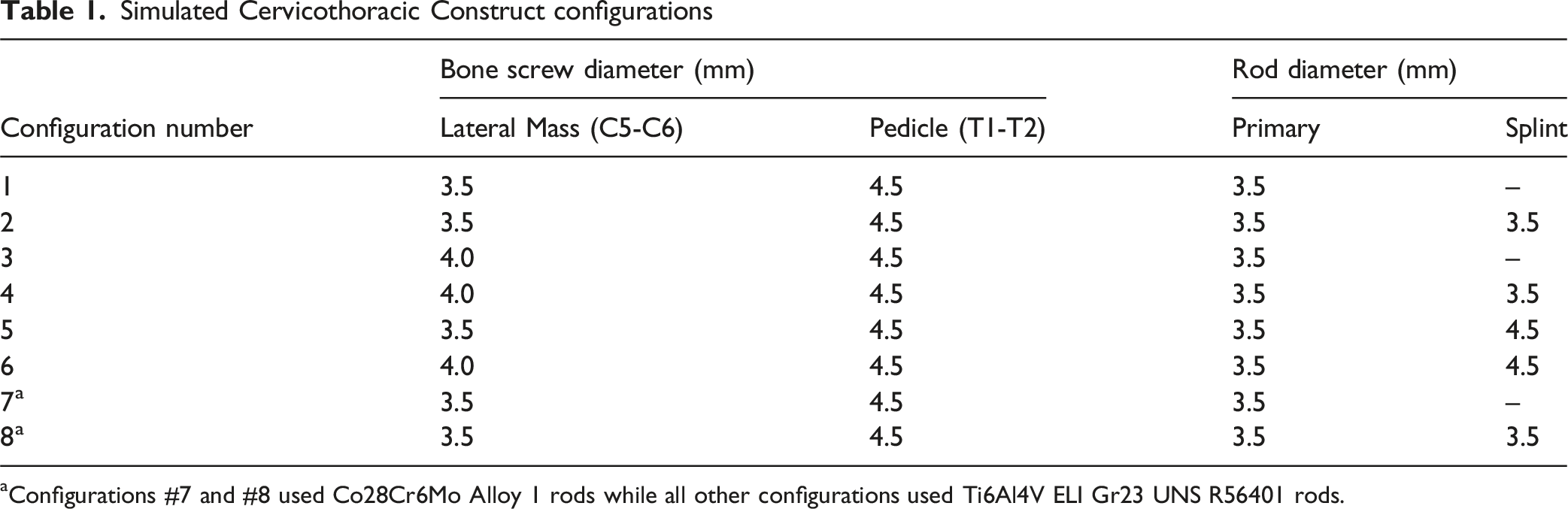
aConfigurations #7 and #8 used Co28Cr6Mo Alloy 1 rods while all other configurations used Ti6Al4V ELI Gr23 UNS R56401 rods.
All components were modelled elastically and without failure criteria. The Von-Mises stress distribution in the construct components was used to predict the location of failure where the magnitude of stress exceeded the material yield stress. Maximum load-bearing capacity (yield load), cranial/caudal displacement at yielding, construct stiffness, and corresponding maximum stresses in the spinal rods and screws under the yield load were measured for each configuration.
FEA Simulation
The vertebral body and bone screw spacing for the construct was adapted and modelled from the mechanical test set-up requirements listed in ASTM F1717 and ISO 12189 employing both a vertebrectomy of C7 (per ASTM F1717) with 2 levels above and below the vertebrectomy (per ISO 12189). Anatomy of the construct and spacing of the vertebrae were defined based on a 50th percentile male spine model.7,8 Construct simulations were designed for straight rods with no lordosis to simplify the model. To simulate screw trajectories into vertebral bodies, lateral mass screws were positioned in a Roy-Camille trajectory (10° lateral off the sagittal plane) and pedicle screws were positioned 15° lateral off the sagittal plane into rectangular blocks simulating vertebral bone.
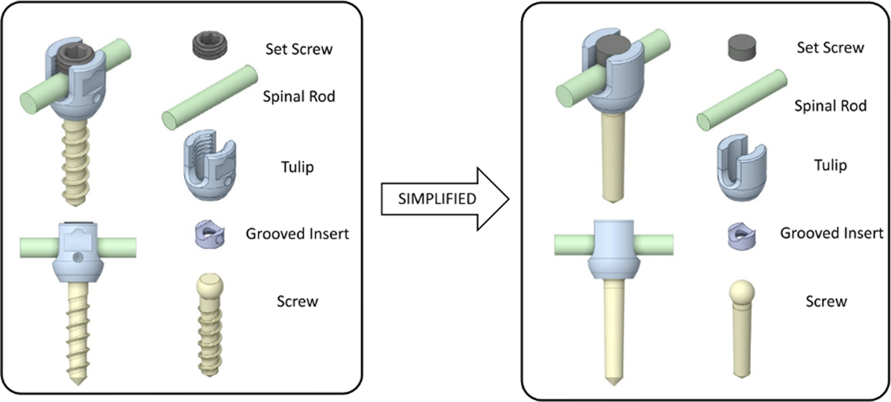
Screw length was constant for the lateral mass (18 mm) and pedicle (30 mm) screws for all configurations. Figure 1 illustrates an example of the designed construct, showing configuration #2 described above (Table 1). All screws were then simplified to remove threading and replaced with equivalent boundary conditions that simulate screw fixation (Figure 2). Design of the C5-C6 to T1-T2 Cervicothoracic Vertebrectomy Construct Showing Configuration #2 With a Section of a Spine From a 50th Percentile Male Model Screw Geometry Simplification for FEA Simulation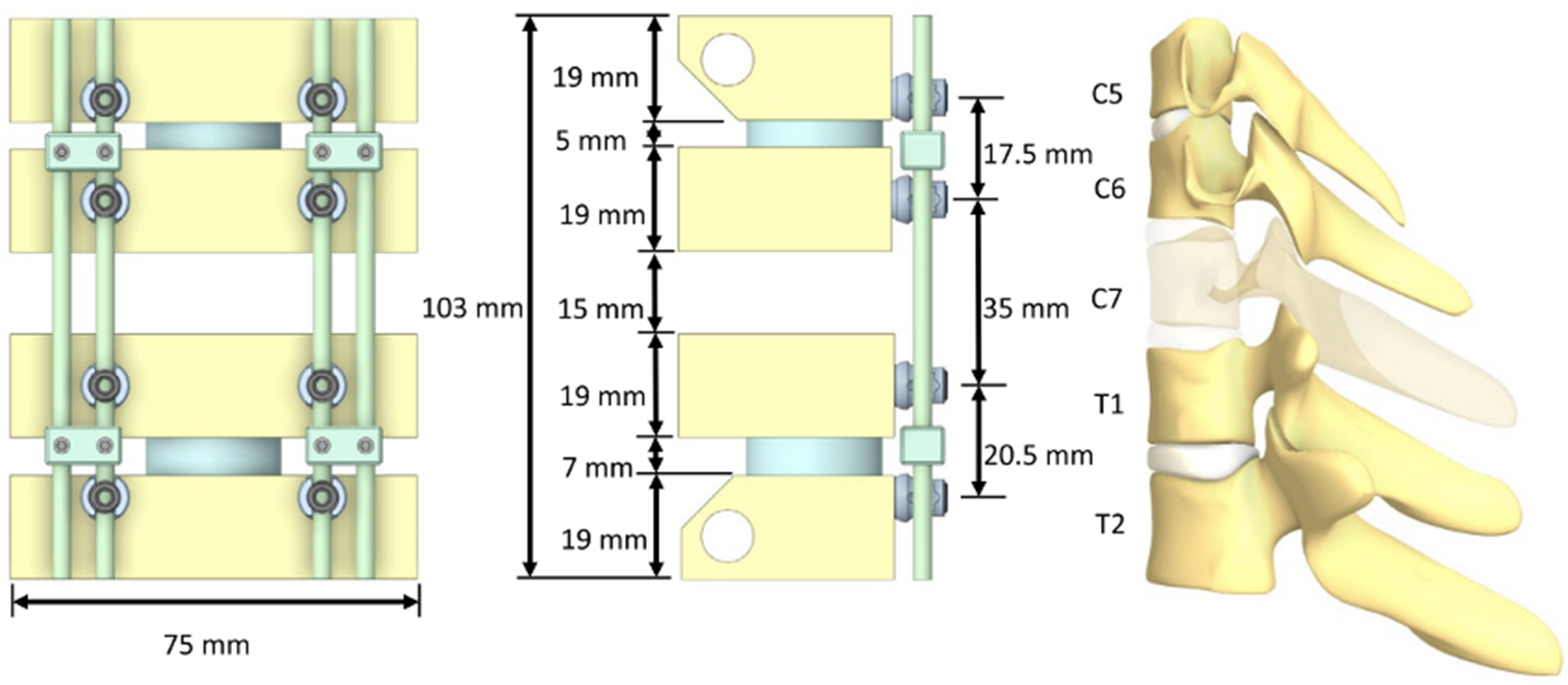
Materials
The rods and screws were modelled to meet the minimum required mechanical properties of ASTM F136 wrought annealed Ti6Al4V ELI Gr23 (UNS R56401) (ρ = 4500 kg/m3, E = 110 GPa, σy = 795 MPa), and annealed low-carbon (alloy 1) ASTM F1537 medical grade wrought Co28-Cr-6Mo (UNS R31537) (ρ = 8300 kg/m3, E = 210 GPa, σy = 517 MPa).9,10 The lateral mass and pedicle screws were inserted into blocks that were modelled to meet the average properties of ASTM F1839 grade 10 rigid polyurethane foam (ρ = 160.2 kg/m3, E = 58.7 MPa, τy = 1.618 MPa), simulating expected vertebral bone stiffness.11-13
To be consistent with the physiological behaviour of intervertebral discs, ISO 12189 recommends the use of ISO 10243 ‘standard compression springs’ that approximate disc stiffness under compression loads.8,14 The intervertebral discs in our construct between C5-C6 and T1-T2 were modelled as simple cylinders using the hyperelastic (rubber-like) properties of human intervertebral disc material from the literature. 15 The discs were modelled based on the mechanical properties of the annulus fibrosus, which makes up the strongest portion of an intervertebral disc (ρ = 1200 kg/m3, E = 500 MPa, Mooney-Rivlin: C10 = 0.560 MPa, C01 = 0.140 MPa, D1 = 1 Pa-1).
Boundary Conditions
Each construct configuration was loaded as shown in Figure 3, where the distal hinge was fixed but free to rotate in flexion/extension and the proximal hinge was free to move in the cranial/caudal direction and in flexion/extension rotation. Worst-case loading was applied by a constant ramping displacement at the proximal hinge until the C6 and T1 vertebral blocks impinged (approximately 2 cm). The applied load on the proximal hinge was measured for each construct and used to determine the load bearing capacity. Loading and boundary conditions applied to the construct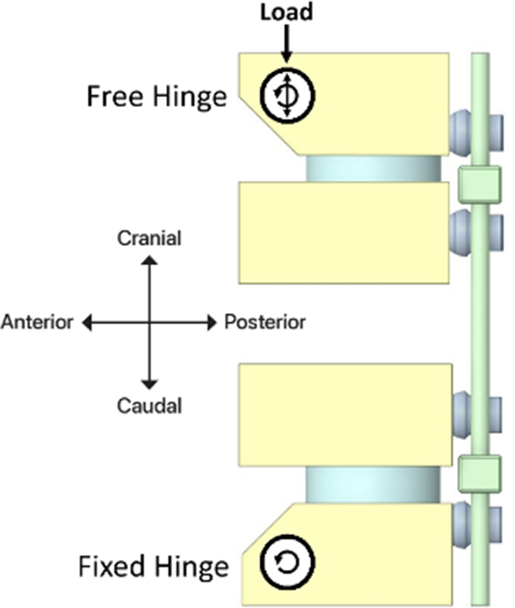
The clamping force applied to the rods by the set screws was calculated to be 10 kN from a tightening torque of 12 Nm measured in similarly sized set screws from the literature. 16 The clamping force was calculated using the formula for the pre-load force which is the axial load generated by a fastener when it is tightened and is a function of tightening torque and friction.
A coefficient of friction of 0.2 was applied to contact surfaces between screw components. To simulate near-perfect fixation while still permitting separation, a higher coefficient of friction of 1.5 was used between the screws and bone. Contact between the modelled discs and blocks was defined as bonded. All components were meshed with linear tetrahedral elements with an element size of 1 mm.
Results
Maximum Load Capacity, Yield Displacement, Construct Stiffness, and Corresponding Component Stresses in Rods and Screws Across all Construct configurations
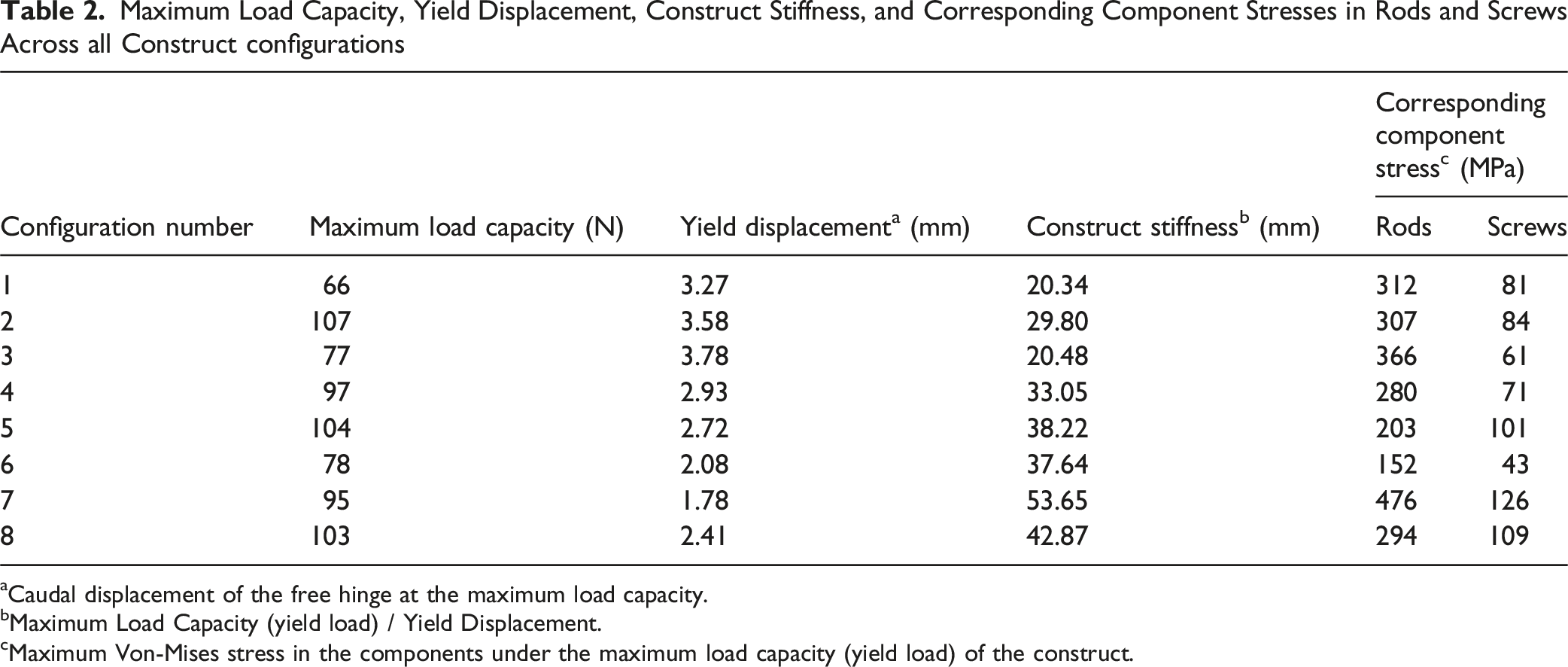
aCaudal displacement of the free hinge at the maximum load capacity.
bMaximum Load Capacity (yield load) / Yield Displacement.
cMaximum Von-Mises stress in the components under the maximum load capacity (yield load) of the construct.
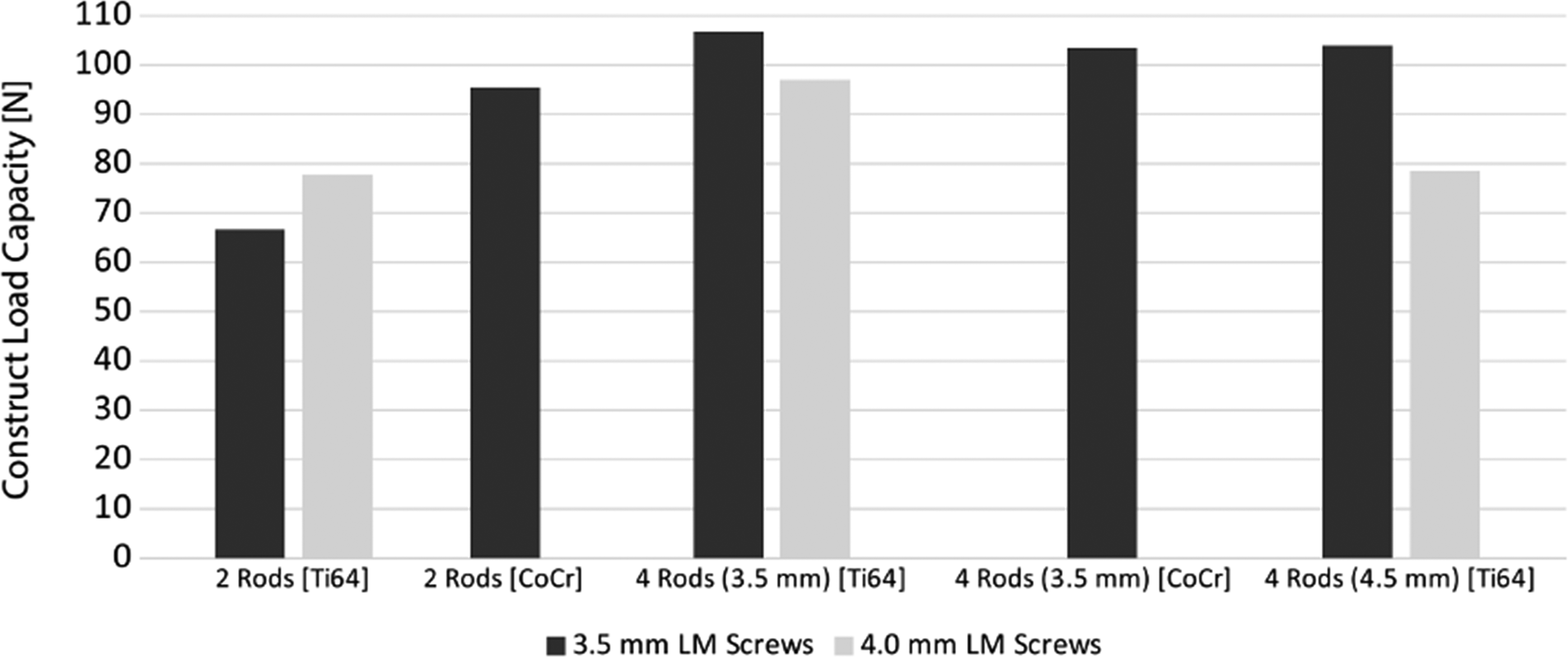
A plot of Construct Load Capacity as a Function of Lateral Mass Screw Diameter, Number of Rods, Rod Diameter, and Rod Material. The Best- and Worst-Case Constructs are Identified as Having the Highest and Lowest Construct Load Capacity, Respectively
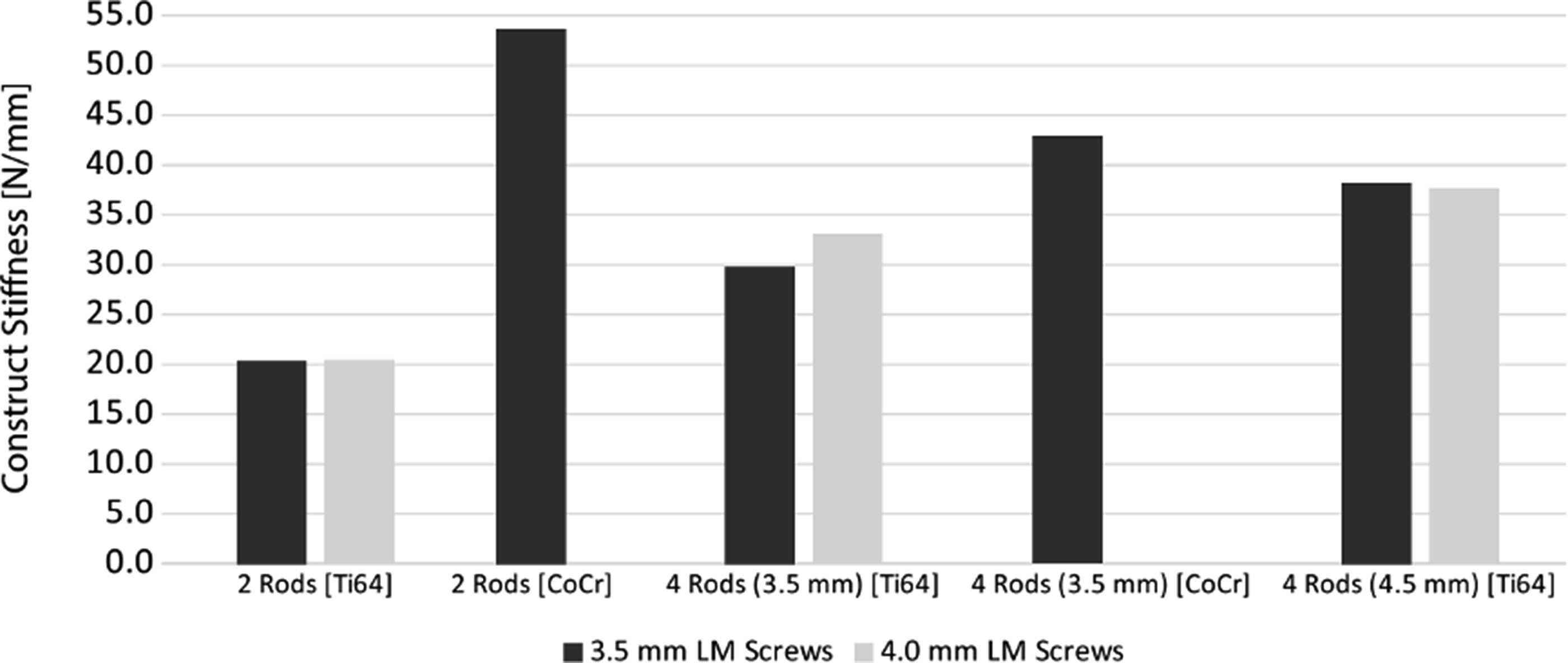
A Plot of Construct Stiffness as a Function of Lateral Mass Screw Diameter, Number of Rods, Rod Diameter, and Rod Material
Notching on the primary rods at level T1 was found as a secondary mode of failure when assuming primary failure in the screw-block interface is contained such that screw loosening is minimized and remains securely fastened to the blocks as would be the case in stronger than modelled bone such as in younger or healthier patients. This secondary mode of failure was caused by pedicle screw tulip impingement under higher loads. Notching in the rods could potentially be an initiation point for fatigue cracking and rod failure.
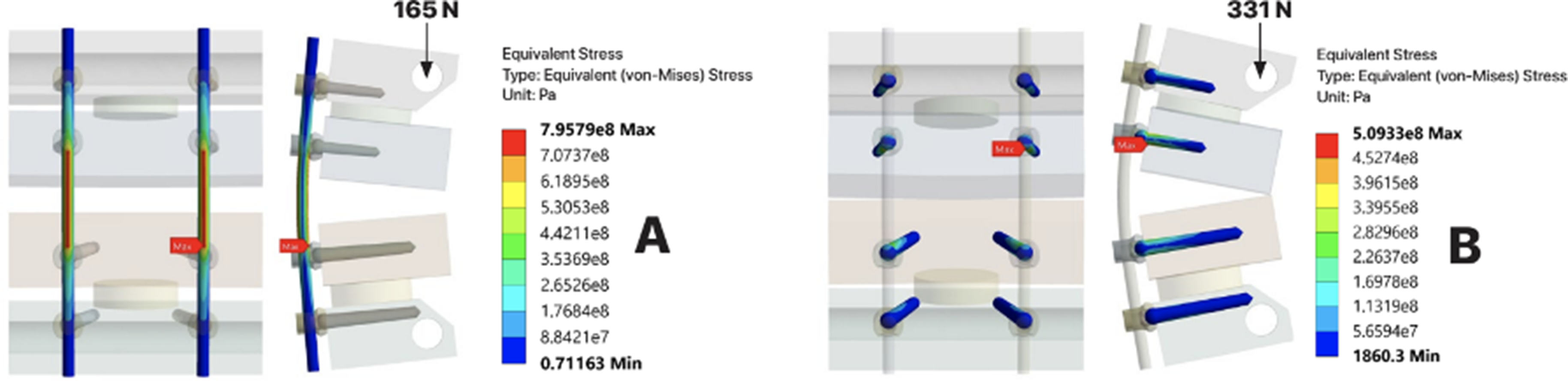
The best-case construct based on load bearing capacity was configuration #2, with a total load-bearing capacity of 107 N. The worst-case construct was configuration #1, with a total load-bearing capacity of 66 N. The difference between the best and worse-case configurations was the addition of 2 splint rods in configuration #2. A comparison of the stress distributions in the polyurethane foam blocks between these 2 configurations is shown in Figure 6. The stress distribution in the rods and screws of configuration #1 at higher loads, as shown in Figure 7, highlights potential secondary modes of failure such as rod notching from T1 tulip impingement. No signs of screw failure were found up to worst-case (highest) loading conditions, the instant when the C6 and T1 blocks impinge. A Comparison of the Von-Mises Stress Distribution in the Polyurethane Blocks of the Best-Case (configuration #2) with a Load-Bearing Capacity of 107 N and the Worst-Case (configuration #1) with a Loading Bearing Capacity of 66 N. The Maximum Stress Shows the Location of Yielding in the Blocks at the Tip of the Lateral Mass Screws in C5 and C6 The Von-Mises Stress Distribution in (A) the rods and (B) the Screws of the Worst-Case Scenario (configuration #1) Showing Yielding in the Titanium Rods Caused by the Impinging Pedicle Screw Tulips at T1 at 165 N, and No Yielding of the Screws When at a Maximum Displacement of 2 cm and 331 N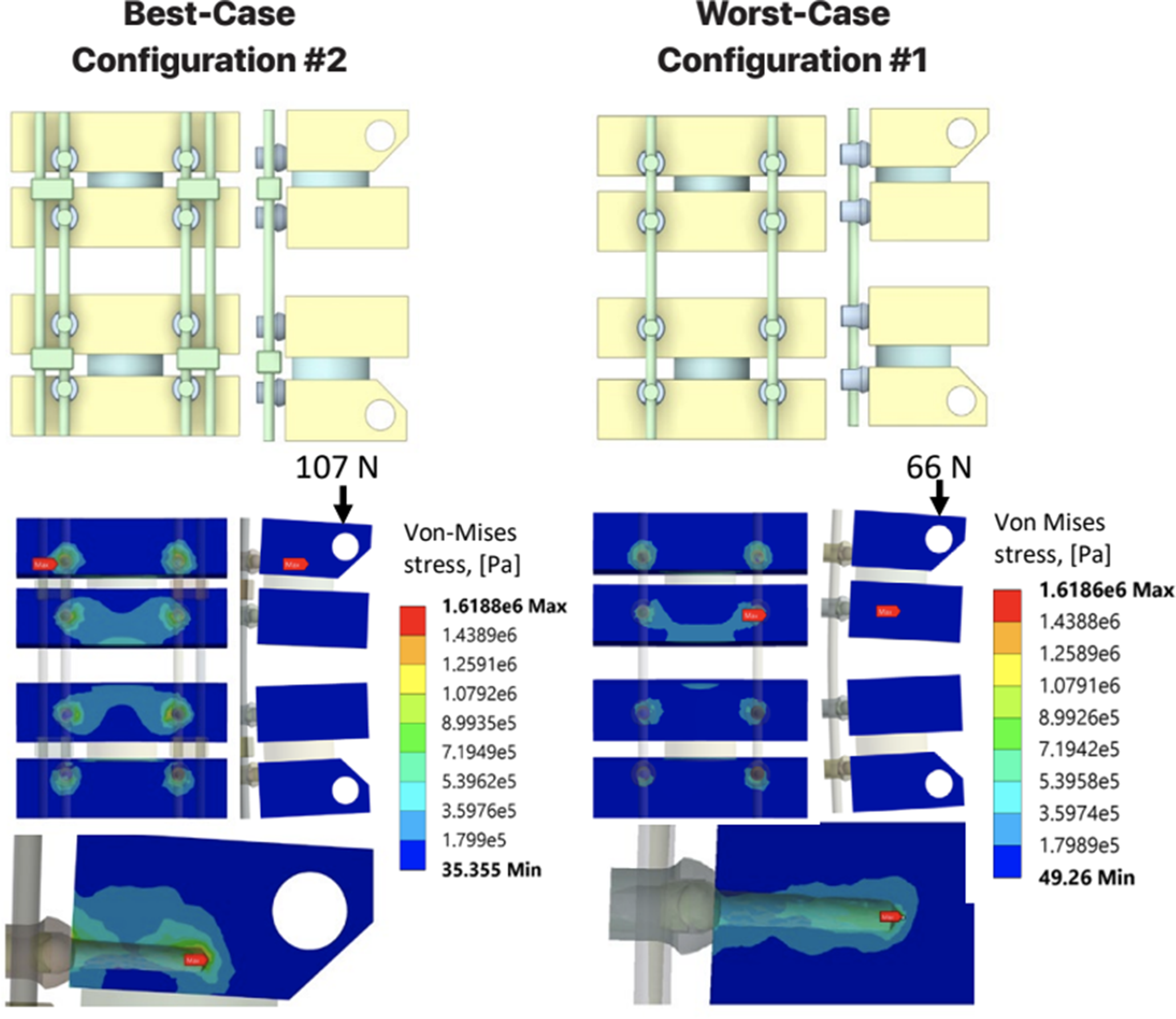
The key findings from this study are: (1) Adding splint rods improves the load bearing capacity of the construct (2) Increasing construct stiffness either through increasing diameter of the rods or screws, or through change in rod alloy to cobalt chrome does not always result in an improvement of the load bearing capacity as it risks earlier failure at the bone-screw interface (3) Optimal construct design is a careful balance between construct stiffness and load-sharing
Discussion
Relevance
Posterior cervicothoracic spinal surgery remains an important treatment option for many patients with adult spine deformity, infectious, neoplastic, or traumatic etiologies. 22 The downside of operative care is the high complication rate of both major and minor complications. Fixation device failure is an important and potentially preventable complication given that the mode of failure is typically related to fatigue over time rather than a single overloading event. 23 Rod fatigue is the most common mode of device failure after complex spinal reconstruction as they must maintain structural integrity while the spine undergoes osseous union. Patient-related factors such as poor bone quality, patient weight, and patient level of activity may be more difficult to meaningfully impact as the surgeon.3, 25 Using a cervicothoracic construct that balances stiffness and load sharing, resulting in overall greater maximum load capacity can improve clinical outcomes by decreasing the risk of hardware failure in complex surgery.
Interpretation
Through finite element modelling, we were able to simulate several common cervicothoracic spinal constructs in a C5-C6 to T1-T2 vertebrectomy model. We have found that adding splint rods increases the stiffness and therefore load capacity of the construct which was as we expected. Configuration #1 was the simplest construct, consisting of 3.5 mm lateral mass screws and 3.5 mm primary titanium rods without the addition of splint rods, and had the lowest maximum load capacity of 66N and a construct stiffness of 20.34 N/mm. In contrast, configuration #2 included the addition of 3.5 mm splint rods and exhibited the greatest maximum load capacity of 107N with a construct stiffness of only 29.80 N/mm. Further stress analysis of the construct in configuration #1 highlighted secondary modes of failure such as rod notching from T1 tulip impingement, however there were no signs of screw failure in the highest loading conditions. The addition of splint rods was found to be the most effective way to increase construct stiffness and mitigate stress concentrations on the primary rods.
Our study found that increasing construct stiffness may not always result in a higher load capacity, rather it is dependent on construct design. Our study found that increasing splint rod diameter from 3.5 mm to 4.5 mm increased the construct stiffness but decreased the maximum load capacity of the construct. This unexpected finding suggests that adding secondary rods (splint rods) may alter load distribution such that there are increased stresses at the screw-bone interface, leading to earlier failure at the lateral mass screws. Pivazyan et al conducted a cadaveric biomechanical study of the impact of splint rods in cervicothoracic constructs and determined that increasing splint rod size leads to increased stability. 4 Their finding agrees with our study as the finding of increased stability can be interpreted to mean increased construct stability, but our study also demonstrates that construct stiffness is not necessarily synonymous with the maximum load capacity of the construct.
We had theorized that risk of screw loosening at the screw-bone interface due to increased construct stiffness could be obviated through the use of larger diameter screws, but we found that was not the case in our study. Our study found that increasing lateral mass screw diameter from 3.5 mm to 4.0 mm minimally impacted construct stiffness but resulted in a paradoxical decrease in maximum load capacity for constructs that included the use of splint rods (both 3.5 mm and 4.5 mm splint rods) due to early screw loosening. It should be noted that our model did show increased maximum load capacity with the use of larger diameter lateral mass screws for the construct without splint rods. Furthermore, increase in lateral mass screw diameter resulted in component stress shifting away from the screws and towards the rods. A possible explanation is that in constructs without additional splint rods, the primary rod is able to take on the load more efficiently, leading to an increase in maximum load capacity as expected with larger lateral mass screws. However, when additional splint rods are introduced into the construct in the context of larger lateral mass screws, they may reduce the construct’s ability to distribute stress evenly across all points of fixation, leading to premature failure at the interface between the larger lateral mass screw and bone.
Change of rod material from titanium to cobalt chrome in the single rod constructs showed significant increase in construct stiffness and maximum load capacity. However, adding cobalt chromium splint rods had a counterintuitive effect and reduced construct stiffness. This behaviour contrasts the findings from Pivazyan et al., where cervicothoracic constructs composed of cobalt chrome splint rods to had greater stiffness than single rod constructs. Due to the higher modulus of elasticity of cobalt chrome, it is possible that introduction of splint rods in this case altered the load-sharing behaviour, leading to a more complex redistribution of forces. The splint rods could have created stress-relief pathways, paradoxically allowing more motion between components. Unfortunately, there is limited data on splint rod biomechanics, but research on similar adjuncts like cross-links has provided evidence that addition of such components can lead to complex stress redistributions that can impact both construct stiffness and motion between components. 17
As mentioned above, there is a paucity of literature examining the biomechanical impact of splint rods in cervicothoracic constructs. The aforementioned biomechanical study by Pivazyan et al which uses cadaveric bone and another biomechanical study by Hartmann et al which uses 3-dimensional printed bone models quantifies the impact of addition of splint rods, size of splint rods, and material of splint rods on cervicothoracic spine range of motion.4,20 Both studies show that addition of splint rods, increased diameter of splint rods, and cobalt chrome rods can all decrease the range of motion of the cervical spine in flexion-extension, lateral bending, and axial rotation which is in contrast to our study that only modelled a single loading condition. However, our study was able to quantify construct stiffness and maximum load capacity, as well as complexities in the screw-bone interface that can be considered more applicable to clinical outcomes such as risk of hardware failure in long-segment spinal arthrodesis.18,19
The results of this study have important clinical implications for understanding and optimizing cervicothoracic spinal constructs. Our findings demonstrate that designing a cervicothoracic fixation is a nuanced decision with many fixation and patient-related considerations. Although our findings suggest that adding splint rods is the most effective strategy for improving construct stiffness and maximum load capacity of cervicothoracic constructs, there is a dynamic relationship between construct stiffness and maximum load capacity. If 1 does not completely understand the complex biomechanics of the cervicothoracic spinal construct, there can be unintentional stress concentrations that could predispose construct failure. Splint rods have been well described to improve stabilization of thoracolumbar spinal constructs resulting in improved clinical outcomes, but further biomechanical and clinic studies need to be conducted with regard to the cervicothoracic spine. 21
Limitations
While this study aimed to evaluate the mechanical performance of construct variations in a cervicothoracic model, we were limited to static loading conditions, homogeneous density bone models, simplified sagittal plane alignment and simplified screw geometry.
Conclusion
The addition of splint rods improved load bearing capacities for all constructs. Increasing splint rod diameter and lateral mass screw diameter led to a paradoxical decrease in maximum load capacity, suggesting shifting stress distributions that may predispose the spinal construct to premature screw loosening or hardware failure. Changing the rod material from a titanium alloy to a cobalt chrome alloy improved the maximum load capacity in a single-rod construct. Our FEM of posterior cervicothoracic spinal constructs provides key insights into how various modifications impact biomechanical stability and how the addition of splint rods may decrease the risk of bone or hardware failure and subsequent revision surgery. 24
This study highlights the importance of construct optimization, as increased stiffness does not always correlate with increased load bearing capacity. Future research should be conducted to better characterize the biomechanical and clinical implications of these findings. Future studies should also include dynamic stress conditions to better understand long-term construct performance and failure mechanisms.
Footnotes
Author contributions
Jaskaran Singh – Data Interpretation, Manuscript Drafting, Submitting for Publication. Ian Polyzois – Data Modelling, Data Analysis, Manuscript Editing, Sara Gustafson – Data Modelling, Data Analysis, Manuscript Editing, Trevor Gascoyne – Secured Funding, Manuscript Editing, Michael Goytan – Idea Conception, Secured Funding, Data Interpretation, Manuscript Editing, Project Supervisor
Funding
The author(s) disclosed receipt of the following financial support for the research, authorship, and/or publication of this article: This study was supported by a research grant from an academic institution (University of Manitoba). All funding was used exclusively for study-related activities. The authors acknowledge the potential for funding-related bias and confirm that the sponsors had no involvement in study design, data collection, analysis, interpretation, or manuscript preparation.
Declaration of conflicting interests
The author(s) declared no potential conflicts of interest with respect to the research, authorship, and/or publication of this article.
Data Availability Statement
The data that support the findings of this study are available from the corresponding author upon reasonable request.