
Abstract
Introduction
Studies document rod fracture in pedicle subtraction osteotomy (PSO) settings where disk spaces were preserved above or adjacent to the PSO. This study compares the multidirectional bending rigidity and fatigue life of PSO segments with or without interbody support.
Methods
Twelve specimens received bilateral T12–S1 posterior fixation and L3 PSO. Six received extreme lateral interbody fusion (XLIF) cages in addition to PSO at L2–L3 and L3–L4; six had PSO only. Flexion-extension, lateral bending, and axial rotation (AR) tests were conducted up to 7.5 Newton-meters (Nm) for groups: (1) posterior fixation, (2) L3 PSO, (3) addition of cages (six specimens). Relative motion across the osteotomy (L2–L4) and entire fixation site (T12–S1) was measured. All specimens were then fatigue tested for 35K cycles.
Results
Regardingmultiaxial bending, there was a significant 25.7% reduction in AR range of motion across L2–L4 following addition of cages. Regarding fatigue bending, dynamic stiffness, though not significant (p = 0.095), was 22.2% greater in the PSO + XLIF group than in the PSO-only group.
Conclusions
Results suggest that placement of interbody cages in PSO settings has a potential stabilizing effect, which is modestly evident in the acute setting. Inserting cages in a second-stage surgery remains a viable option and may benefit patients in terms of recovery but additional clinical studies are necessary to confirm this.
Keywords
Flat-back deformity is characterized by the loss of lumbar lordosis, which often leaves the patient significantly functionally impaired. It was initially described as a postural disorder resulting from distraction instrumentation used for scoliosis treatment 1 ; however, it has been increasingly recognized that a variety of pathologies may decrease the lumbar lordosis that leads to flat-back deformity. These most commonly include posttraumatic kyphosis, iatrogenic flat-back syndrome, posterior fusion without structural grafting, and postlaminectomy kyphosis. 1 , 2 , 3 To maintain horizontal gaze, these patients develop adaptive changes including decreased pelvic tilt, hip extension, knee flexion, and hyperextension of the cervical spine to maintain sagittal balance, which leads to intractable pain and early fatigue and pain of paraspinal musculature and quadriceps. 1 , 2 , 3 , 4 Therefore it is critical to restore and maintain lumbar lordosis and sagittal balance for patients with flat-back deformity.
Historically, treatment has involved one or more osteotomies involving a combined anterior-posterior approach, anterior-only procedure, or posterior-only procedure. 1 , 2 Reconstruction of flat-back deformity poses many challenges and all these surgical approaches have significant complication rates. 1 For many years, the Smith-Petersen osteotomy was the most commonly selected procedure for deformity correction, which is limited by the anatomical constraints of the anterior column. 2 More recently, the pedicle subtraction osteotomy (PSO), which is a single-stage posterior procedure that affects all three columns of the spine, has emerged to be the selected procedure for flat-back deformity because it does not lengthen the anterior column, it provides a large degree of segmental correction, and the greater bone-on-bone contact promotes higher fusion rates. 3
There have been only a few longitudinal studies in which the authors tracked the outcomes and complications of the lumbar PSO, in which a variety of complications has been reported. 1 , 3 , 5 These studies documented poor clinical results with pseudarthrosis associated with implant failure at the osteotomy site, which results in revision surgeries. 3 A recent clinical study evaluating correlations with symptomatic rod fracture found that of 442 patients, 15.8% had rod fractures following PSO for posterior instrumented fusion for correction of adult spinal deformity. Of this subset, 89% had rod fracture located at or adjacent to the PSO site. 6 Clinical observations suggest that the most common association for pseudarthrosis was rod fracture at the PSO level. This occurred with higher frequency in individuals in whom the disk spaces were preserved above and below the PSO level. In this situation, intact disks anteriorly with posterior nonunion at the osteotomy site results in a circumferential nonunion that leads to implant failure. In cases of pseudarthrosis, reinstrumentation with interbody grafts for additional support may be beneficial for stability as well as for fusion substrate.
The use of structural interbody cages in the setting of PSO is a recent technique. A variety of lumbar interbody fusion techniques have been documented including anterior, posterior, and transforaminal approaches, but Cappuccino et al 7 have demonstrated that the extreme lateral interbody fusion (XLIF) construct provides the largest stand-alone reduction in range of motion (ROM) partially due to its large surface area for fusion and preservation of the anterior longitudinal ligament and annulus. 8 , 9
The purpose of this study is to compare the multidirectional bending rigidity and fatigue life of PSO spinal segments with or without interbody support above and below the osteotomy site. We hypothesized that interbody support would provide greater load share with the posterior rods, thereby increasing the fatigue life of the construct.
Methods
Specimen Preparation and Treatment Groups
Twelve fresh-frozen human spines (four women, eight men; 72 ± 12 years old; T12 to sacrum) were studied. Anterior-posterior and lateral X-rays were taken of each specimen prior to full dissection to confirm normal anatomy and lack of metastatic tumors. Standard anterior lumbar dual X-ray absorptiometry (DEXA) scans were taken of each specimen with the L1–L4 region mapped on the DEXA scanner's internal software (Hologic QDR-2000, Hologic, Inc., Bedford, MA) to exclude severely osteoporotic specimens (T-score >−2.5).
Following radiographic assessment, the spinal sections were cleaned of muscles and connective tissue with care taken not to disrupt ligaments and intervertebral disks. The cranial (T12) vertebrae was potted in a polymer casting agent (Smooth Cast 300, Smooth-On, Easton, PA) and the sacrum was potted in the polymer casting agent up to just below S1 to facilitate rigid fixation to the test frame during biomechanical testing.
Treatment Groups
All 12 specimens received posterior instrumentation and a closing wedge PSO was performed at L3. The PSO included a partial L2 and partial L4 laminectomy, and a complete L3 laminectomy and pediculectomy as well as wedge decancellation of the L3 vertebra (approximately 30 degrees 10 , 11 , 12 ). The posterior instrumentation included titanium alloy (Ti-6Al-4V) polyaxial pedicle screws (6.0 × 45 mm) inserted bilaterally from T12–S1 (excluding L3), all of which were connected by 5.5-mm cobalt chrome (CoCr) rods. Half of the specimens (n = 6, male/female = 4/2) received structural interbody cages at the L2–L3 and L3–L4 levels (Fig. 1) and the other half (n = 6, male/female = 4/2) did not. Although there are several commercially available lateral interbody spacers available for the lateral interbody fusion (LIF) procedure, this study specifically used XLIF cages. Cages were sized individually to best fit each specimen; however, 18 × 55-mm footprint XLIF cages with 10-degree lordosis were most commonly used.
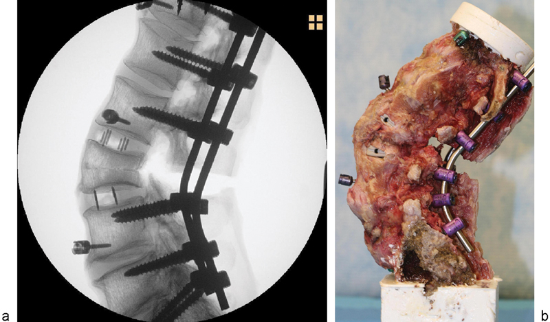
(a) X-ray and (b) digital image of specimen instrumented with 5.5-mm cobalt chrome rods and structural interbody cages with a pedicle subtraction osteotomy performed at L3.
Biomechanical Testing
ROM Bending Tests
Multidirectional bending tests were conducted on each spinal section for each of the aforementioned test groups using a cable-driven pure moment testing apparatus 13 , 14 , 15 , 16 (Fig. 2a) mounted to a uniaxial hydraulic press (858 MiniBionix, MTS, Eden Prairie, MN).
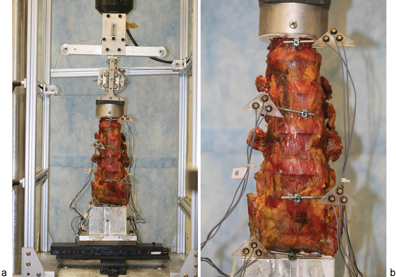
(a) Entire cable-driven pure moment test setup showing T12–S1 specimen. (b) 3-D motion tracking probes.
This validated 3-D sliding ring setup 16 system functions by inducing a pure moment at the top of the specimen via a counterbalanced loading ring on vertical bearings with a single cable wound around the ring creating a force couple upon tensioning. Cable tension levels are controlled via the throw of the uniaxial hydraulic actuator, and applied moment is calculated as a function of the loading ring size and the cable tension as measured by the uniaxial load cell mounted to the hydraulic actuator. Changing the direction of the ring and cable allows for loading in the three anatomical directions of flexion-extension (FE), right/left lateral bending (LB), and right/left axial rotation (AR) of the entire spinal segment. To ensure the spine is unconstrained in the plane of the MTS base, two linear sliders were placed perpendicular to one another at the base of the spine.
During the bending tests, relative motion across the entire fixation site (T12–S1) and across the osteotomy site (L2–L4) was measured using a 3-D motion tracking system (Optotrak 3020, Northern Digital, Waterloo, Ontario, Canada). Rigid body markers (each consisting of three individual infrared sensors) were rigidly attached to the T12, L2, L4 vertebrae and the potting fixture (which rigidly held the sacrum and pelvis) via cervical lateral mass screws (3.5 × 16 mm; Depuy, Warsaw, IN) placed anteriorly in the vertebral body (Fig. 2b). These screws were positioned so as not to interfere with the implants being studied, and this was confirmed following each surgery using planar X-ray (Philips BV Pulsera, Philips Healthcare, Andover, MA). Relative motion of the vertebrae was tracked in real-time from the 3-D camera system using custom-designed software (FlexWin 2009, Barrow Neurological Institute, Phoenix, AZ), which has a validated accuracy of 0.1 degrees for spinal testing. 14
Nondestructive flexion-extension (FE), LB, and AR tests were performed on each specimen in accordance with a standard protocol. Specifically, specimens were preconditioned in each test direction by applying three cycles of 0 to 7.5 Newton-meters (Nm) at 0.02 Hz followed by a 60-second hold at 0 Nm. Following preconditioning, specimens were quasi-statically loaded in increments of 1.5 Nm every 45 seconds to a maximum of 7.5 Nm. The ROM test groups were as follows: (1) posterior instrumentation (T12–S1 with iliac fixation, excluding L3; instrumented group), (2) L3 PSO, and (3) addition of structural interbody cages (for 6 of the 12 specimens) at the L2–L3 and L3–L4 levels (XLIF group).
Fatigue Bending Tests
Following the ROM testing, specimens were shortened to include only L2–L4 with the cranial and caudal ends of the specimens, including the fusion rods, rigidly cast in plastic resin. Fatigue bending tests were conducted on all 12 specimens at 2 Hz in moment control between anatomic region-specific limits of 8 Nm in flexion and −6 Nm in extension for 35K cycles. The 35K cycles was to simulate a 3-month postoperative period, assuming 125,000 “significant bends” per year. 17 The estimated number of cycles is between 30K to 35K, and 35K was selected as a worst-case loading condition for the implants.
A “significant bend” was defined as one full cycle between +8 Nm of flexion and −6 Nm of extension with the spine under 400 N of axial compression. The axial compressive load of 400 N was selected based on established values in the literature for net compressive load in the spine. 18 This protocol, which has been frequently used in the literature, 19 , 20 , 21 , 22 , 23 has been validated by numerous studies 18 , 24 , 25 , 26 , 27 to simulate the full ROM of the lumbar spine for physiological levels of muscle activity.
Testing was interrupted at specified cycle intervals (0K, 2.5K, 5K, 10K 20K, 35K) to assess pedicle screw and structural interbody cage migration and subsidence. At the end of each cycle interval, anterior-posterior and lateral radiographs were recorded at loaded times of flexion, extension, neutral (zero moment), and 0 degrees with a C-arm (Philips BV Pulsera) positioned around the test frame (Fig. 3). The position of the C-arm was locked at the start of the fatigue test to allow for a consistent reference frame for all migration/subsidence measurements. Specimens were hydrated with a physiological saline solution every 10 to 15 minutes throughout testing to minimize tissue dehydration.
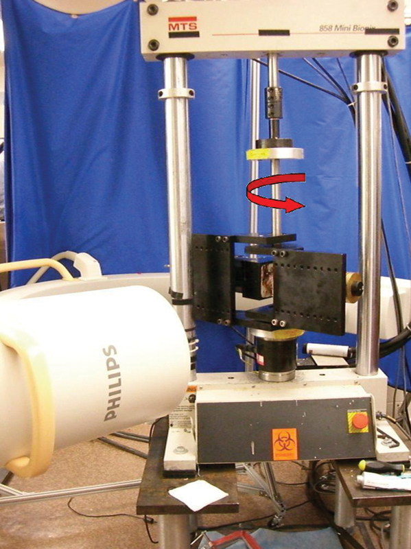
The test jig used for flexion-extension and lateral bending testing of the lumbar spine. The C-arm encircles the test jig. The red arrow indicates the directions of the applied torque.
Outcome Measures
ROM Bending Tests
Multidirectional bending rigidity was compared across the test groups for the motion segments T12–S1 (across the entire site) and L2–L4 (across the osteotomy site) using the maximum ROM in the primary loading direction. Statistical analyses were performed using commercially available software (JMP v5.0, SAS Institute, Inc., Cary, NC). Once the data was determined to follow a nonparametric distribution, repeated-measures analysis of variance using ranks with paired comparisons were made using Wilcoxon/Kruskal-Wallis tests to analyze differences between test groups. The level of significance for all statistical tests was set at p < 0.05.
Fatigue Bending Tests
Dynamic stiffness, defined as the torque divided by L2–L4 rotation at the limits of +8 Nm/ − 6 Nm of FE averaged over the last four cycles for each selected cycle interval, was compared for spines with (n = 6, PSO + XLIF) and without structural interbody cages (n = 6, PSO only). Rotational stiffness (Nm/degree) is a measure of mechanical integrity by evaluating the rotational displacement given an applied moment. Percent change from initial stiffness was calculated for the flexion, extension, and total stiffnesses. Statistical analysis with a generalized estimating equations model was performed by a trained statistician using commercially available software (SAS v9.2, SAS Institute, Inc., Cary, NC). The level of significance for all statistical tests was set at p < 0.05.
Results
No significant differences were found in DEXA scores between specimens assigned to each test group (p > 0.05).
ROM Bending Tests
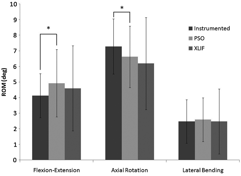
Significant differences were found between all AR ROM test groups only across the osteotomy site (L2–L4, Fig. 4). Specifically, there was a 25.7% reduction in AR ROM following addition of structural interbody cages to one level above and below the PSO site. The addition of cages also reduced FE ROM by 35.8% across the osteotomy site, but this difference was not significant (p = 0.873).

Range of motion (ROM) across the osteotomy site (L2–L4) for flexion-extension, right/left axial rotation, right/left lateral bending of the instrumented, pedicle subtraction osteotomy (PSO) only and PSO + extreme lateral interbody fusion (XLIF) groups before fatigue testing. Error bars denote ± 1 standard deviation. Asterisks above bars connected by lines denote significance. Significant differences were noted between PSO versus XLIF (p = 0.007), between instrumented versus PSO (p < 0.001), and between instrumented versus XLIF (p = 0.004).
Across the entire fixation site, significant differences were found only between instrumented and PSO test groups for both FE and AR ROM (p = 0.015 and p = 0.009, respectively, Fig. 5); p values for all ROM bending test results are represented in Table 1.
p values for statistical comparisons across the entire fixation (T12–S1) and across the osteotomy (L2–L4) in the ROM bending tests
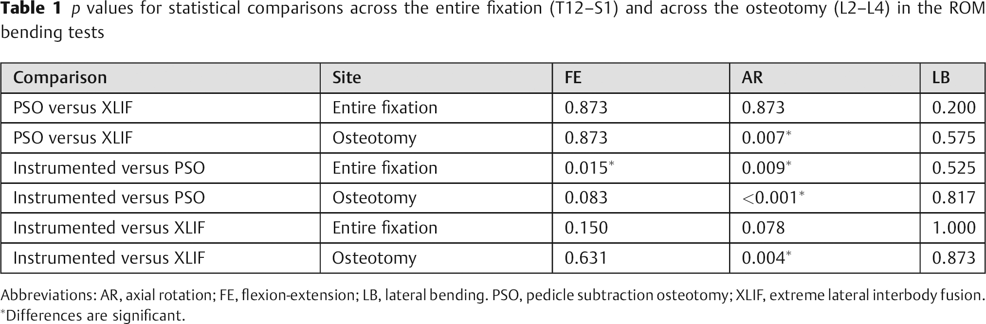
Abbreviations: AR, axial rotation; FE, flexion-extension; LB, lateral bending. PSO, pedicle subtraction osteotomy; XLIF, extreme lateral interbody fusion.
Differences are significant.
Range of motion (ROM) across the entire site (T12–S1) for flexion-extension (FE), right/left axial rotation (AR), right/left lateral bending of the instrumented, pedicle subtraction osteotomy (PSO) only and PSO + extreme lateral interbody fusion (XLIF) groups before fatigue testing. Error bars denote ± 1 standard deviation. Asterisks above bars connected by lines denote significance. Significant differences were noted between Instrumented versus PSO for both FE (p = 0.015) and AR (p = 0.009).
Fatigue Bending Tests
The group that received structural interbody cages (PSO + XLIF) increased from an average initial stiffness of 10.34 ± 3.09 Nm/degree to an average final stiffness of 13.23 ± 4.62 Nm/degree, indicating an average 35.61 ± 67.42% increase from total initial stiffness after 35K cycles. The group that did not receive structural interbody cages (PSO only) increased from an average initial stiffness of 8.50 ± 3.06 Nm/deg to an average final stiffness of 9.53 ± 3.58 Nm/deg, indicating an average 13.39 ± 34.56% increase from total initial stiffness after 35K cycles. This change in dynamic stiffness from initial to final was 1.86 Nm/deg greater and 22.2% greater in the group that received structural interbody cages after 35K cycles (PSO + XLIF) than the group that did not receive structural interbody cages (PSO only); however, this difference was not significant (p = 0.095, Fig. 6). There were also no observable instances of cage migration, subsidence, or pedicle screw pullout from the radiographic measurements for both groups that did and did not receive structural interbody cages.
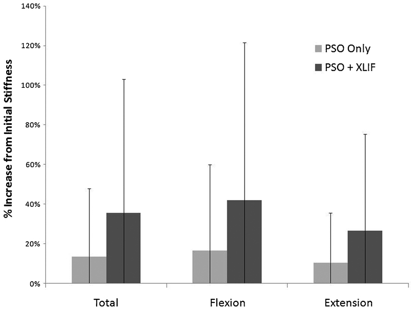
Percent increase from initial dynamic stiffness for total (flexion + extension), flexion, and extension stiffnesses following the fatigue bending tests for pedicle subtraction osteotomy (PSO) only and PSO + extreme lateral interbody fusion (XLIF) groups. Error bars denote ± 1 standard deviation. There were no significant differences noted.
Discussion
The results of this study provide some evidence that interbody cage support adjacent to a PSO with bilateral pedicle screw fixation can increase construct rigidity. The stiffening effect of the cages is evident immediately postoperatively (“acute”) as the ROM for specimens with and without structural interbody cages was statistically distinguishable in AR. However, there was no observed difference between groups in FE and LB at this time. During 3 months of simulated physiological activity, there was a trend for the presence of structural interbody cages to increase bending rigidity over the group without cages after some period of fatigue loading by up to 22%, but this failed to reach the level of statistical significance. The increase in stiffness following fatigue bending for both groups of specimens with and without structural interbody cages is likely due to the prolonged effects of bone-on-bone compaction at the PSO site.
It is possible that placement of interbody cages has a more comprehensive effect on construct rigidity and that the experimental design was simply not sensitive enough to detect it. Specifically, as with all biomechanical studies, the sample size was relatively low and the posterior rods (5.5-mm CoCr) tended to dominate all ROM and stiffness measurements. Considering the limitations of the experimental approach, our results indicate that a higher sample size may be needed to elucidate any substantial effects of interbody cage immediately postoperatively in FE and LB and during the 3-month postoperative healing period in which cages may help to maintain construct integrity under repetitive loading.
There are several other limitations to this study that should be acknowledged. First, as with any cadaveric study, the loads on the construct are only an approximation of the actual physiological situation due to the inherent lack of muscle forces. Furthermore, for the fatigue test setup, a long fusion construct (e.g., T12–S1) was simulated with a shorter spine segment surrounding the osteotomy site (L2–L4) with the cranial and caudal ends of the specimens, including the fusion rods, rigidly cast in plastic resin. This was done to facilitate testing on our compression/fatigue test frame, and it may have induced some artifacts by creating a much stiffer model than would be expected clinically. However, we believe that these artifacts were relatively small compared with the effect size we were looking to detect, and the testing was performed in the same manner on both treatment groups. Finally, a longer postoperative simulation may have elucidated greater differences between specimens with and without interbody cage placement.
There are several strengths to this study. The repeated-measures test design during the ROM bending tests strengthens this study by controlling for interdonor effects so that each specimen serves as its own control. In addition, the experimental design examined motion under multiaxial bending conditions to an accuracy of 0.1 degrees, 14 and the validated custom testing apparatus ensured pure moment loading conditions. 15 , 16 The fatigue bending tests also enabled more accurate evaluation of construct rigidity and hardware fatigue life over time by simulating a period of 3 months postoperative.
Intuitively, the addition of structural interbody cages in the disk spaces above and below the PSO site potentially improves fusion rates by limiting mobility and strengthening the anterior spinal column, which would subsequently prevent early rod failure. The fatigue strength of CoCr has also been previously shown to be greater than that of titanium alloy, particularly with notching of the rod (e.g., rod bending zones 28 ), and an additional factor to consider in future studies would be whether clinical failures have been observed with titanium or CoCr posterior fusion rods.
The results of this study suggest that placement of interbody cages through an LIF approach in the setting of PSO has a potential stabilizing effect, which is only modestly evident in the acute setting. Inserting structural interbody cages in a second-stage surgery, as is currently done by the clinician authors, remains a viable option. As rod fracture is not an altogether infrequent occurrence, and because preliminary clinical observations currently suggest that patients with LIF cages have less likelihood of rod fracture, it may be worthwhile to insert these cages in the acute setting to prevent future probability of revision surgery. Because the LIF technique is minimally invasive and patients recover quickly with minimal hospital stay, 29 inserting these cages in a second-stage procedure may even be a benefit to patients in terms of recovery. Of course, future clinical or biomechanics studies are necessary to confirm these clinical observations and should consider longer follow-up times (greater than 3 months), differences in rod materials, and greater sample sizes to better elucidate differences between groups.
Disclosures
Vedat Deviren, Consulting: NuVasive, Stryker, Medtronic, Synthes, Guidepoint; Research Support: NuVasive; Fellowship Support, Indirect institutional support OREF Omega, AOSpine, Globus, NuVasive
Jessica A. Tang, None
Justin K. Scheer, None
Jenni M. Buckley, Research Support - Investigator Salary: Stryker Spine; Research Support - Staff and/or Materials: DePuy Spine; Grants: NuVasive
Murat Pekmezci, Research Support Grants: Stryker, NuVasive
R. Trigg McClellan, Device or Biologic Distributorship (Physician-Owned Distributorship): PDP Holdings; Stock Ownership: Biomineral Holdings; Private Investments: Total Connect Spine, Anthem Orthopaedics, PDP Holdings; Consulting: Advanced Biologics Corporation, Skeletal Kinetics; Board of Directors: Northern California Chapter, Western Orthopaedic Association, PDP Holdings, Anthem Orthopaedics; Scientific Advisory Board: Anthem Orthopaedics; Research Support - Staff and/or Materials: NuVasive
Christopher P. Ames, Consulting: DePuy, Medtronic, Stryker; Employment, UCSF; Grants/grants pending: Trans1; Patents: Fish & Richardson, PC; Royalties, LANX, AESCULAP; Stock/stock options: Trans1, Visualase, Doctors Research Group