
Abstract
Study Design
In-vitro biomechanical study.
Objectives
Injuries or degenerative conditions can lead to atlantoaxial instability requiring fixation. We aim to assess and compare the biomechanics of a C1-C2 posterior arch and translaminar screw construct against the Harms procedure for posterior atlantoaxial fixation on a human cadaveric model.
Methods
Nine human cadaveric cervical specimens from occiput to C3 (C0-C3) were used for range of motion (ROM) testing. Each specimen was tested for 4 configurations: 1. Intact, 2. Destabilized, 3. Harms construct, 4. C1-C2 posterior arch screw (PAS) construct. A pure moment of 1.5 Nm was applied, and ROM of the C1-C2 segment was measured in flexion-extension, lateral bending, and axial rotation.
Results
The Harms group showed a decrease in ROM in all modes (P < 0.021), and the PAS group showed a decrease in ROM in flexion-extension and lateral bending (P < 0.002), but not in lateral bending (P = 0.176). Compared to the intact condition, Harms showed increased ROM for flexion-extension (P = 0.012), and PAS did not (P = 0.258). In lateral bending, both constructs did not significantly reduce ROM (P > 0.058). In axial rotation, both constructs showed a significant increase in ROM (P < 0.002). There was no significant difference in ROM when comparing Harms with PAS in flexion-extension (P = 1.000), lateral bending (P = 0.163), or axial rotation (P = 1.000).
Conclusions
The study demonstrates that a C1-C2 PAS construct restores or increases biomechanical stability compared to the intact condition. C1-C2 PAS offers similar biomechanical stability compared to the Harms construct.
Introduction
The atlantoaxial joint, which consists of the atlas (C1) and axis (C2), is unique in its anatomy as it lacks an intervertebral disc between C1 and C2. The unique anatomy and the absence of a disc result in a high level of mobility at this level and a reliance on ligaments and the joints’ articular and osseous structures for stability. A variety of injuries or degenerative conditions such as trauma, arthritis, tumors, infection or congenital malformation can lead to atlantoaxial instability. Instability at the atlantoaxial joint can lead to severe pain, mobility impairment, neurological damage and death.
Several different screw placement techniques have been described to stabilize the atlantoaxial spine effectively. The Harms screw placement technique is the most popular surgical intervention for stabilizing the atlantoaxial joint. 1 The method involves placing screws in the C1 lateral mass and the C2 pedicle. Although the Harms technique has proven to be effective at stabilizing the atlantoaxial joint, complications can arise due to the proximity of neural structures and the location and anatomical variation of the vertebral artery around C12,3 and the foramen transversarium (FT) of C2. 4
The anatomy of the C1 posterior arch and C2 lamina offers a fixation option that avoids excessive bleeding that can be caused by dissection through the C1–C2 venous plexus, and possible neurovascular damage during screw insertion by avoiding the lateral vessels. Additionally, this anatomy can serve as a location to place screws to salvage a C1/2 fusion. Techniques for the insertion of C1 posterior arch and C2 laminar screws have been described5,6 and morphometric data on the bicortical diameter and height of the C1 lamina based on computerized tomography (CT) data suggests that 76% of people are likely to be candidates for C1 posterior arch screws. 7 Also, it has been shown that the C2 vertebra can tolerate a 3.5 mm translaminar screw in 76% of cases. 8
Although the approach for positioning C1 posterior arch and C2 translaminar screws may circumvent some of the challenges inherent to the Harms procedure, the small bone cross-section poses new issues, such as requiring precise screw placement to accommodate bilateral screw placement. Also, the small bone cross-section can be prone to cortical breakout, carrying the risk of loss of fixation and damage to the dura and the spinal cord located just anterior to the C1 and C2 posterior arch. However, studies have been conducted that support the feasibility of C15,7 and C28,9 laminar screw placement. Additionally, intraoperative navigation and recent advances in additive manufacturing of patient-specific guides have shown promise in simplifying screw placement in the spine.10-15
Several different C1 and C2 laminar crossing screw placement techniques have been described,5,6,16 but there is a lack of evidence in the literature of the use of both methods combined. C1 or C2 lamina screws are primarily used in a unilateral arrangement or associated with lateral mass or pedicular screws.17-20 In this study, we propose to investigate the biomechanical stability of a C1 posterior arch and C2 bilateral translaminar construct.
Materials and Methods
Specimen Preparation
After approval from the Western University Health Science Research Ethics Board (HSREB #115355), 9 fresh-frozen human cadaveric cervical specimens from occiput to C3 (C0-C3) (8 male and 1 female; mean age: 66.6 ± 6.3 years) were used in this study for non-destructive range of motion (ROM) testing. The cadaveric specimens were obtained through a third-party organization that collects donated bodies for research purposes and is responsible for obtaining consent from the family members. No specific consent form was required for the present study. Specimens were frozen at −20°C, and CT imaging was performed to screen for structural abnormalities. Before testing, the specimens were thawed at room temperature overnight and kept moist during all procedures. A fellowship-trained orthopedic spine surgeon removed all surrounding soft tissue with care taken to preserve the joint capsules, disc, and bony structures.
C0 and the lower portion of C3 were rigidly fixed, standardized, into a plastic PVC pipe filled with anchoring cement (KING, Oakville, ON, Canada). Screws were placed into non-essential portions of C0 and C3 to aid in the fixation between the bone and cement. The PVC pipes were then fitted into a customized material testing machine consisting of an x-y bearing table caudally and cranially electromechanical testing machine, allowing for non-destructive ROM testing of the cervical spine (Figure 1). A rigid body containing multiple optical markers was attached to a K-wire and rigidly secured into C1 and C2. Test setup of modified Instron 5967 dual column test frame and digital image correlation system.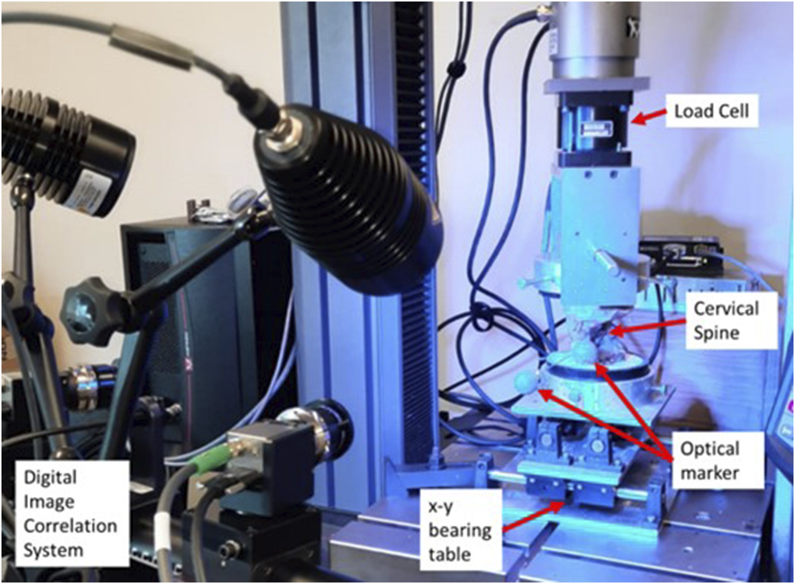
Biomechanical Testing
All mechanical testing followed previously established standardized testing protocols.21,22 Specimens were loaded quasi-statically with a pure bending moment of 1.5 Nm, and axial load was maintained at zero (±0.5%) throughout all tests. ROM testing was done in the 3 axes: flexion-extension, left/right lateral bending, and left/right axial rotation. A custom-designed modification to a 5967 Dual Column test frame (Instron®, Norwood, MA, USA) allowed the application of a pure moment in flexion/extension, lateral bending, or torsion. Each specimen was loaded for 3 cycles at 1 deg/s to 1.5 Nm. The first 2 cycles act as pre-conditioning cycles to minimize the viscoelastic effects, and the last cycle was used for analysis. 21 Motion was captured using ARAMIS (Trilion, King of Prussia PA, USA), a digital image correlation system capable of measuring 3D motion. The system uses 2 cameras to capture the 3D location (±0.002 mm) of the optical markers located on rigid bodies attached to each vertebra.
Testing Sequence
Intact spines were tested first to establish the baseline ROM characteristics of each specimen. Following intact testing, the spines were destabilized by osteotomizing the base of the odontoid to simulate a type II odontoid fracture. Finally, the spines were repaired with both the Harms technique (Figure 2A) and the posterior arch screw (PAS) construct (Figure 2B). (A) Harms surgical construct and (B) Posterior Arch Screw Construct.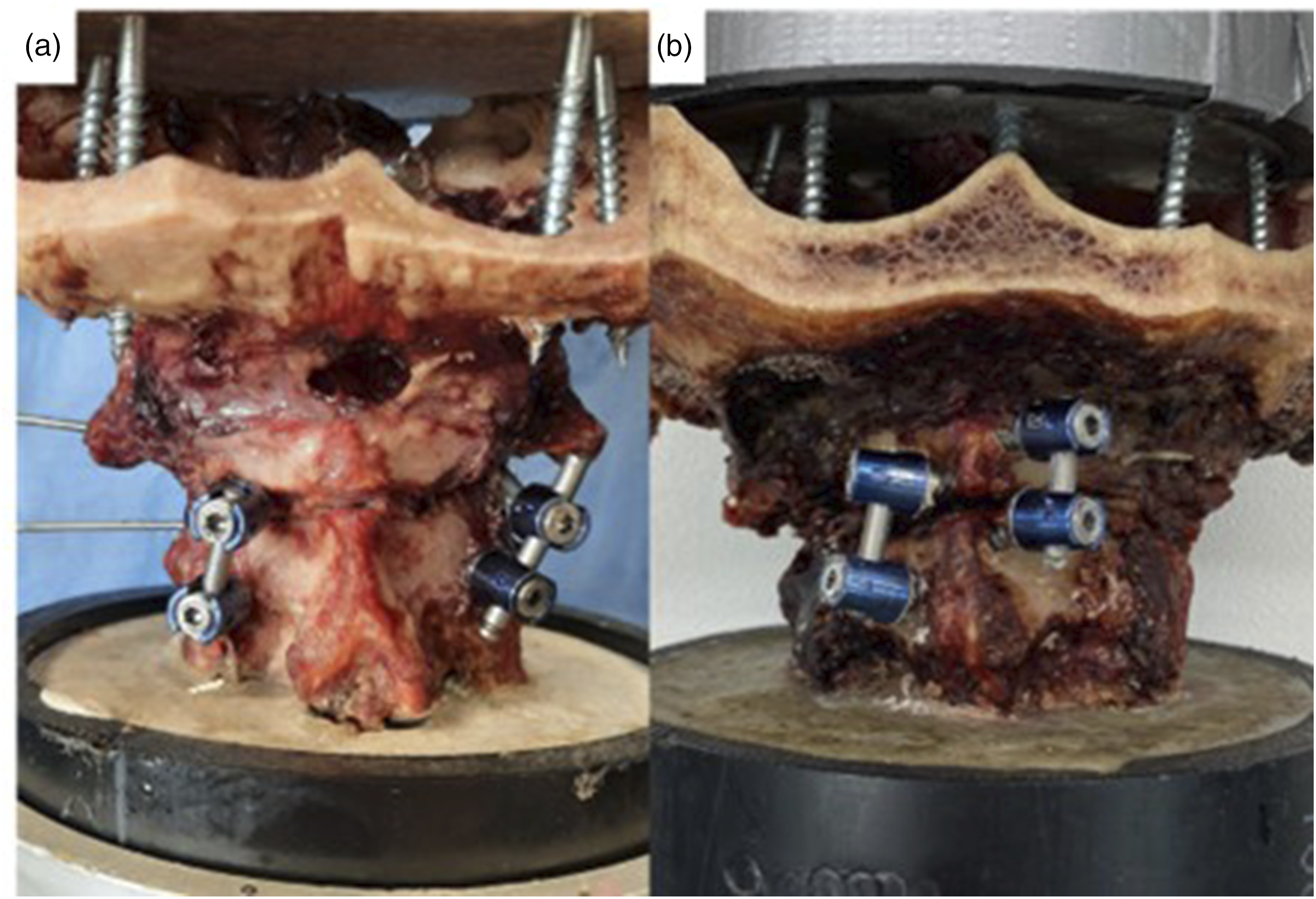
For the Harms technique, a 2 mm drill bit was used to create a pilot hole in the C1 lateral mass and the C2 pedicle. The holes were tapped, and a 3.5 mm polyaxial screw (Infinity, Medtronic) was placed, followed by rods. For the PAS technique, custom drill guides were used to aid in screw placement. Patient-specific drill guides were designed in 3D Slicer using the cadaveric CT scans and fabricated using a 3D printer (Form2, Formlabs). The complete methodology for developing the guides and their accuracy assessment has been previously published
23
(Figure 3). Additional soft tissue dissection was carried out on the posterior arch, spinous process and lamina to accommodate the placement of the guides. A 2 mm drill bit was used to create a pilot hole into the C1 posterior arch and C2 lamina. The hole was then tapped, and a 3.5 mm polyaxial screw (Infinity, Medtronic) and a rod were placed. All the screws used for testing had the same diameter. In C1 posterior arch, the length of the screws was 20 mm; in C2 posterior arch and C2 pars screws, the length was 22 mm; and for the C1 lateral masses, partially threaded 34 mm screws were used. C1(A) and C2 (B) coronal, sagittal and axial views for screws trajectory planning for creation of the 3D printed guides to avoid a trajectory of collision within the laminas.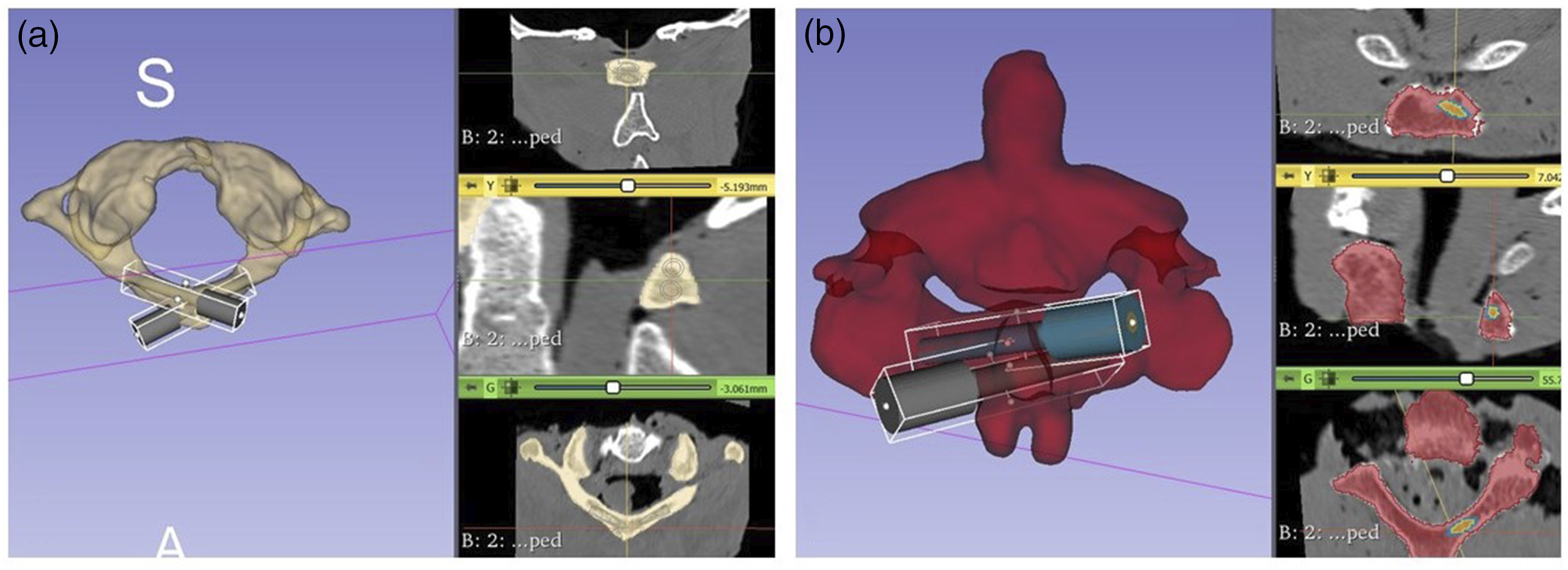
The order in which repair method was performed and tested first was randomized using a random number generator to remove any bias that could be caused by testing order. Also, after every test, a visual inspection of the cadaveric specimens was performed to assess for possible fractures that could have affected the results, and if identified, the sample would be excluded from the final analysis. Also, at the end, we dissected the cadavers completely to assess for breaches in the C1 lamina arising from the bilateral screw insertion.
Data Analysis
Images from the ARAMIS system were processed using the software package GOM Correlate (ZEISS, Braunschweig, Germany), which allowed the 3D coordinates of each marker to be determined. A local coordinate system for each vertebra was created using 3 reference points on each rigid body. The relative angular motion between the 2 axes is calculated. The peak angles calculated during the third cycle were extracted for further analysis.
To determine the effect each condition (ie, intact, destabilized, and repair constructs) had on the ROM, a repeated-measures analysis of variance (ANOVA) was performed. Post-hoc analyses were performed with a Bonferroni adjustment. All statistical analysis was performed using SPSS Version 26 (SPSS Inc, Chicago, IL, USA). Alpha was set at 0.05 for all statistical tests.
Results
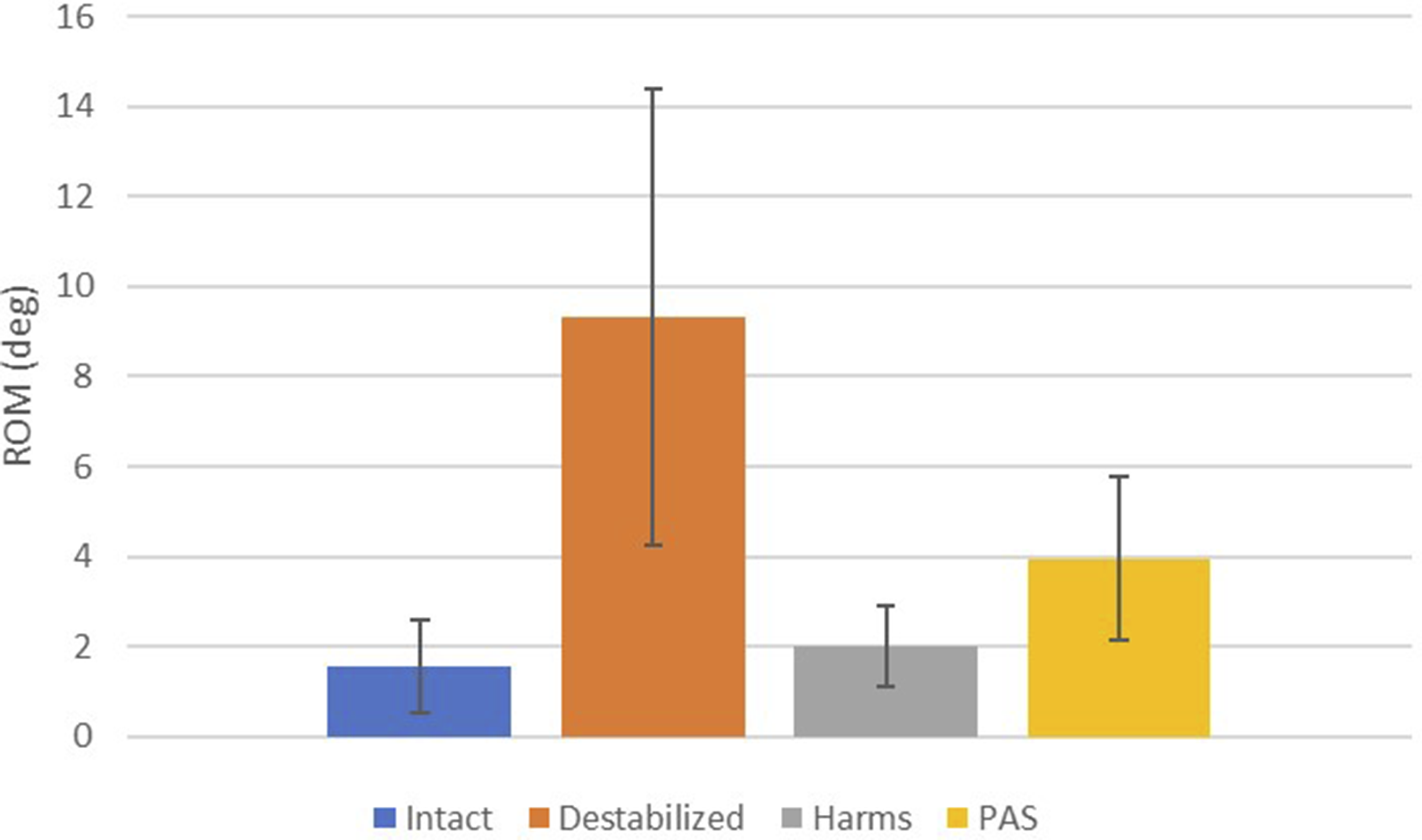
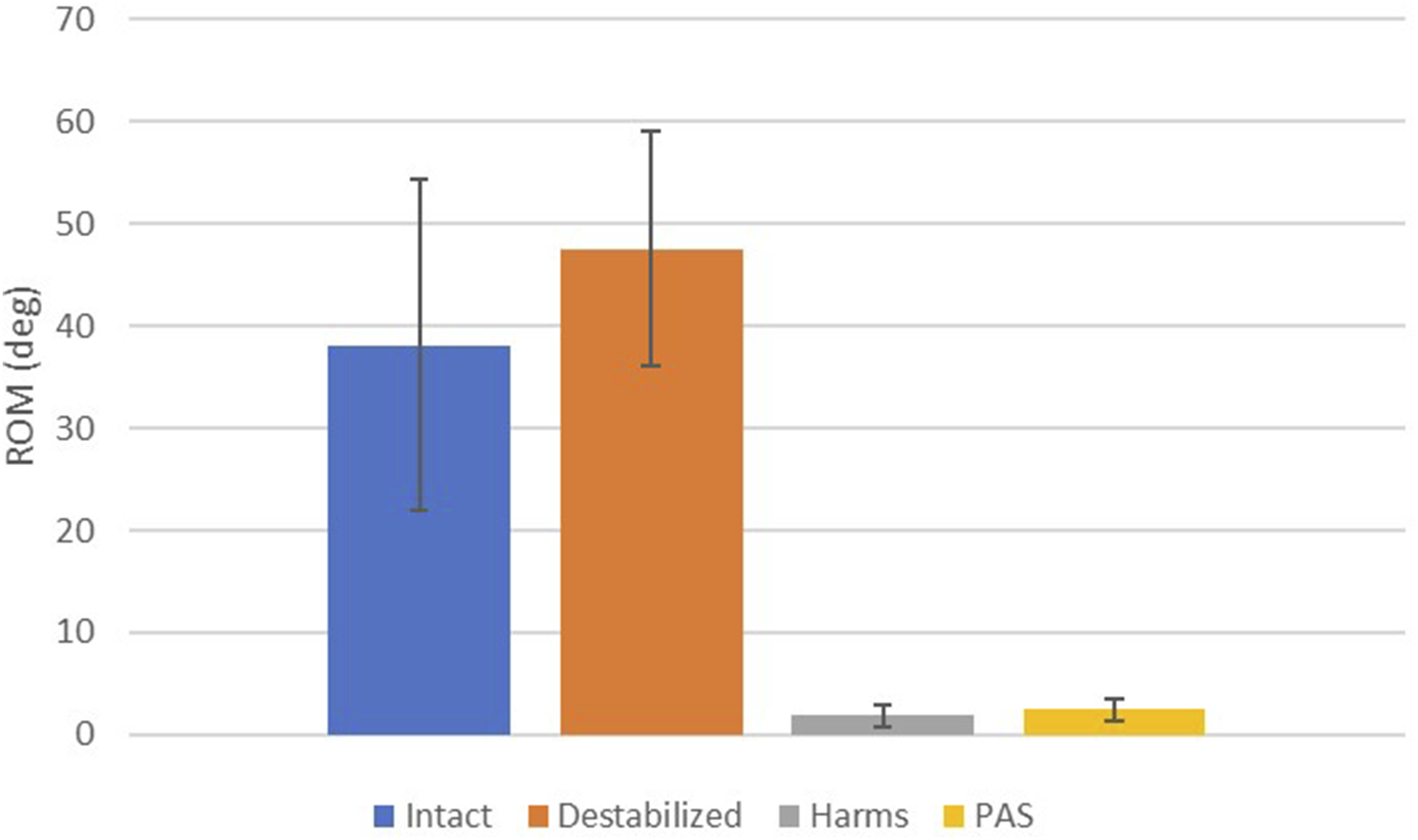
The results of the present study are summarized in Figures 4–6. After testing, no fractures were identified during visual inspection in any of the specimens for any of the configurations. Also, only 1 cadaveric specimen had a minor cortical breach from the screw threads in the inner cortex of the C1 arch, but it did not compromise the stability of the construct. The Harms group significantly decreased ROM when compared with the destabilized condition for flexion-extension, lateral bending, and axial rotation (P < 0.021). The PAS group significantly decreased ROM when compared with the destabilized condition for flexion-extension and axial rotation (P < 0.002) but not in lateral bending (P = 0.176). In flexion-extension, the Harms group showed a significant decrease in ROM compared to the intact condition (P = 0.012), while the PAS group did not (P = 0.258). In lateral bending, the Harms and PAS groups did not show a significant difference in ROM compared to the intact condition (P > 0.058). In axial rotation, the Harms and PAS groups showed a significant decrease in ROM compared to the intact condition (P < 0.002). There was no significant difference in ROM when comparing Harms with PAS in flexion-extension (P = 1.000), lateral bending (P = 0.163), or axial rotation (P = 1.000). Flexion-extension range of motion graph for intact, destabilized, Harms, and PAS. Lateral bending range of motion graph for intact, destabilized, Harms, and PAS. Axial rotation range of motion graph for intact, destabilized, Harms, and PAS.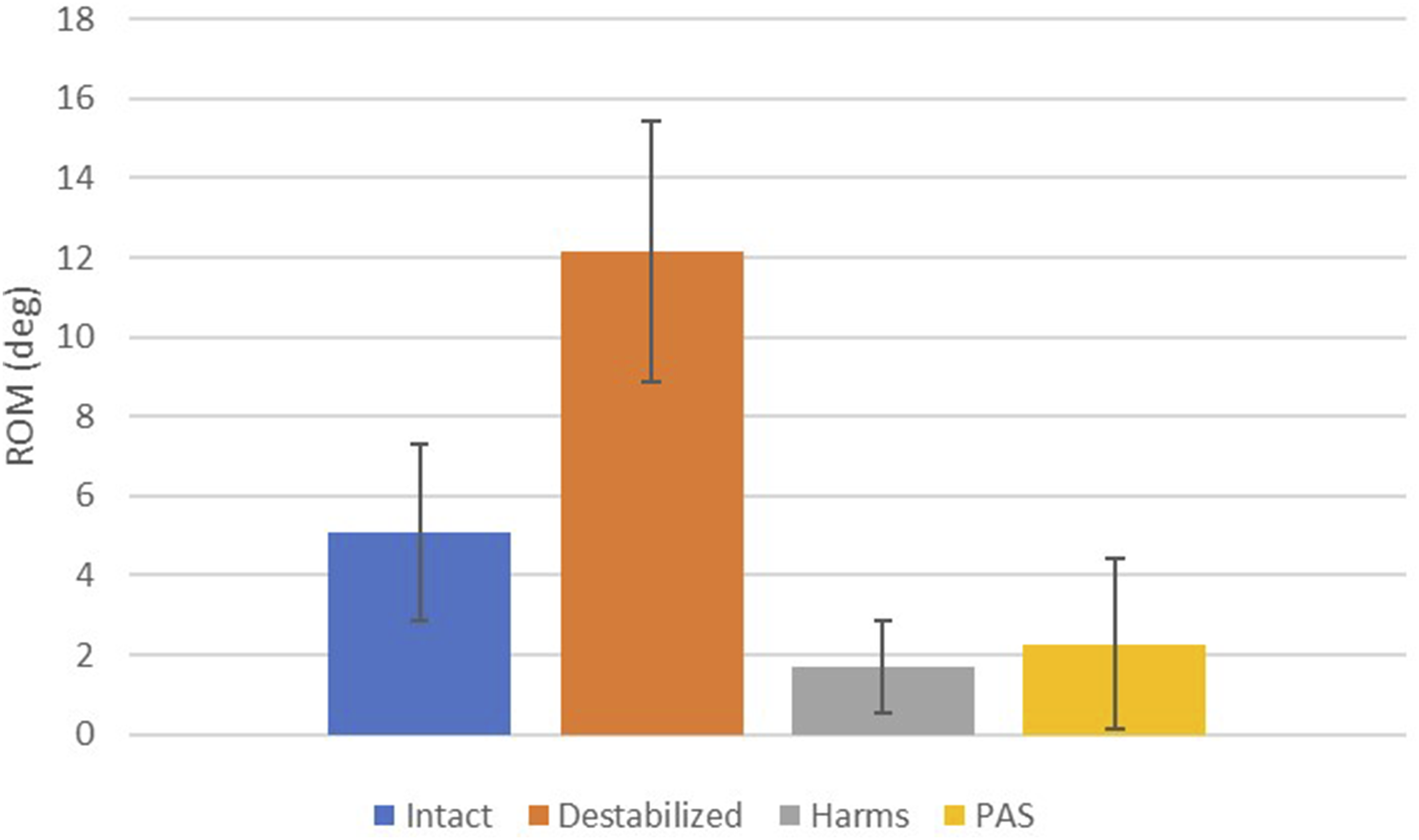
Discussion
Comparison to Prior Work
To the authors’ knowledge, no other study has explored C1-C2 fixation with posterior arch screws combined in the same construct as a surgical alternative to the Harms method. In the authors’ view, this construct represents the least invasive method to stabilize the C1-C2 level as it requires the least amount of lateral dissection for screw placement. This could help avoid injuries to the venous plexus of C1-C2, the vertebral arteries and the C2 nerve root.
While C1 lateral mass screws remain the gold standard for posterior C1 fixation, this biomechanical study highlights the relevance of C1 posterior arch screws not only as a salvage technique in cases where lateral mass screw placement is unfeasible but also as a viable alternative in select patients with favourable anatomy. Given the technical considerations and anatomical variations, understanding the indications and feasibility of this technique expands surgical options and may enhance patient outcomes in specific clinical scenarios.
The results presented here were compared to prior studies to confirm the validity of the methodology. Variation in overall results could be due to anatomical variance, bone quality, loading fixtures, protocol variation, etc. Current intact ROM for flexion-extension (5.08 ± 2.23°) is similar to results presented by a similar study on C1-C2 ROM (7.0°). 24 Similarly, the current intact ROM for lateral bending (1.55 ± 1.04°) overlaps with similar studies (1.6°–3.5°).24-26 Furthermore, current intact ROM for axial rotation (38.11 ± 16.19°) falls within a range of similar results (35.7°–47.5°).25,27-29
Biomechanical Implications
Each specimen served as its own control, and the repair method was alternated to offset/reduce bias from the prior test on the specimen. The Harms and PAS constructs significantly decreased ROM from the destabilized condition in flexion-extension and axial rotation. However, only Harms showed a statistically significant decrease in ROM from the destabilized condition in lateral bending. However, when comparing the 2 constructs, there were no significant differences in ROM for flexion/extension, lateral bending or axial rotation. The lack of statistical difference between the 2 constructs implies that the PAS construct provides biomechanical stability similar to that of the gold standard technique Harms. Therefore, this study’s results provide evidence that the PAS technique could be used as an alternative or a salvage method for C1-C2 fixation.
Although the mean ROM of all 3 modes (flexion-extension, lateral bending, axial rotation) were not significantly different, the Harms construct trended towards lower ROM. The location of the rods could explain this in relation to the centre of rotation of each mode. Due to the location of the screws in the PAS construct, the rods are consistently closer to center line of the spine when compared to the Harms technique. This results in a smaller second moment of area and polar moment of inertia (ie, lower bending and torsional rigidity). Loads transferred from the skull to C1 would transfer near the location of the facets or at the location of ligaments attachment. A larger moment arm is present since the PAS construct results in rods closer to the center line. The Harms technique places screws in the lateral mass which positions the rods inline with the facets thereby resulting in a shorter moment arm. The result of the larger moment arm is particularly apparent in the lateral mode, where the ROM is nearly twice as large in the PAS construct. This is expected as the Harms construct should see almost no bending moment in the lateral mode, as illustrated in Figure 7. A separate clinical study would be required to determine if the extra motion in the PAS construct would affect clinical outcomes such as fusion rates. However, it is essential to emphasize that axial stabilization, which is considered the most critical motion mode, is similarly stabilized in Harms (1.84°) and PAS (2.48°). Depiction of the resulting moment arm caused by the location of the rods. The curved arrow indicates the direction in lateral bending. The straight arrows indicate forces transferred through the facet. The hollow rectangle is the location of the rods for the Harms technique, and the solid rectangle is the location of the rods for the PAS construct. The dotted line represents the moment arm between the force application and the PAS rod.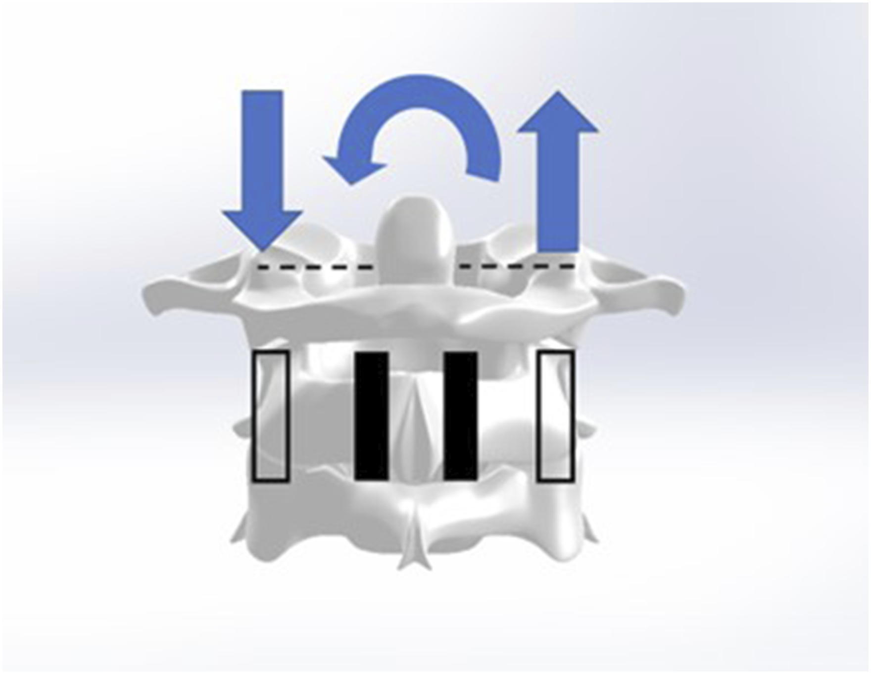
Clinical Considerations
Anatomical studies have shown that it is possible to apply crossed screws to the posterior arch of C1 in large part of the population. However, a literature review identified only 1 case report where C1-C2 fixation with posterior arch screws was combined in the same construct. 7
The lack of application of this technique is likely related to the technical difficulty of inserting the posterior arch screws due to the low margin of error accepted for its placement. However, several methods have been described to guide its placement.5,6 Also, intraoperative navigation and additive manufacturing are promising technologies that have shown to increase screw placement accuracy in the spine.30-36 Despite a study showing that 76% of the population 7 can accommodate laminar screws in the C1 posterior arch, in our sample of convenience, we were capable of placing 2 screws (3.5 mm diameter) in all our cadaveric specimens. Possibly, it was facilitated by the creation of additively manufactured guides that allowed the perfect entry point for both screws to avoid a trajectory of collision. 23
Moreover, all the screws used in this study had the same diameter. Still, it is known that increases in the diameter of the screws would be capable of increasing stability and resistance to pull-out forces, and although increasing the length of the screws can also promote stability, the magnitude of the effect is less noticeable than the increase in diameter. 37
This study showed that the use of combined posterior arch screws in C1 and C2 attain biomechanical stability equivalent to the Harms procedure for C1-C2 fixation and brings the first biomechanical evidence of the possibility of using this technique as an alternative for C1-C2 stabilization. Despite the less invasive nature of our proposed fixation method, a similar concern is the potential risks of injury to the vertebral artery inside the groove. In our cadaveric study, with careful planning and the use of guides, we did not see any breaches in the VA groove because of a misplaced screw tip, but that has to be in consideration when performing in-vivo procedures. Also, there is a potential concern of hardware prominence due to the superficial aspect of the screw’s entry points, but a case report did not show any complications after 2 years of follow-up. 7 Careful patient body habitus selection may help mitigate the risk of the hardware being prominently displayed or even exposed due to inadequate soft tissue coverage.
Potential Limitations
This study possesses limitations that are inherent to in-vitro cadaveric studies, and as with any in-vitro cadaveric study, clinical application should be taken with caution. Following conventional protocol, a pure moment of 1.5 Nm was used as Wilke et al. 21 recommended. Therefore, no muscle or shear forces were included in the model, which may or may not be present in-vivo. 1.5 Nm is typically used as it is well within elastic range, allowing for multiple tests for several loading modes and implants while achieving normal range of motion. 21 Additionally, the construct was only tested in quasi-static loading, and no attempt was made to assess the fatigue performance of the model. Fatigue tests would be required to determine if the posterior arch of C1 is more prone to earlier failure than the typical C1 lateral mass fixation used in Harm’s technique. However, quasi-static loading is typical for a study on construct biomechanical stability. 21 This study only measured the range of motion and did not evaluate construct stiffness or pull-out strength. Future clinical trials should aim at comparing clinical outcomes and screw placement accuracy between these procedures. If the clinical success rate is similar between the 2 groups, C1-C2 PAS may offer a less invasive approach, which could result in a lower complication rate.
Conclusion
The study demonstrates that a C1-C2 PAS construct can restore or increase biomechanical stability compared to the intact condition. C1-C2 PAS offers biomechanical stability similar to that of the Harms construct. Similar early biomechanical stability can be expected if C1-C2 PAS is utilized as an alternative to C1 lateral mass screws and C2 pedicle/pars screws during atlantoaxial fixation.
Footnotes
Declaration of Conflicting Interests
The author(s) declared the following potential conflicts of interest with respect to the research, authorship, and/or publication of this article: Medtronic provided all the implants free of charge through the External Research Program (ERP) but did not provide funds directly to the institution or the researchers.
Funding
The author(s) received no financial support for the research, authorship, and/or publication of this article.