
Abstract
Study Design
Cadaveric Biomechanical.
Objective
To investigate the biomechanical characteristics of a new screw trajectory, which we have deemed the “pedicle inlet” trajectory.
Methods
Four surgeons familiar with standard and image-guided cervical pedicle screw fixation techniques placed 3.5 mm diameter cervical fixation screws randomized at each sub-axial level to one of three fixation techniques: cervical pedicle, pedicle inlet, and lateral mass screw. A total of 180 screws were placed from C3 to C7 in 18 cadaveric spine samples. Maximal insertional torque was measured during the final seating of the screws. After confirmation of accuracy of screws with post-procedural CT-imaging, individual screws in the cadaveric samples were biomechanically tested for pull-out strength.
Results
All screws were placed without breach into neurovascular spaces. The final insertional torque was equivalent (ANOVA, P > .05, 3.6 ± 1.7 Nm) across cervical pedicle screws, pedicle inlet, and lateral mass screws. Maximal pullout strength was observed for cervical pedicle screws (814.6 ± 387.3 N). Pedicle inlet screws had a 51% higher pullout strength as compared to lateral mass screws (593.2 ± 289.9 N v 392.4 ± 284.0 N, P < .01). All differences were statistically distinct from each other (ANOVA, P < .01).
Conclusions
Use of image-guidance allows for safe placement along the pedicle inlet trajectory, with no recorded screw malposition, and a 51% improvement in pull out strength as compared to lateral mass screws. The pedicle inlet trajectory offers an alternative to traditional lateral mass screws with better fixation quality and may have particular application in percutaneous or minimally invasive posterior fusions.
Introduction
Multiple techniques are available for placement of posterior instrumentation in the sub-axial cervical spine. The most widely used method involves placement of a screw into the cancellous bone of the lateral mass. Several techniques for lateral mass fixation have been described, but all share a common start-point near the middle of the lateral mass, and a trajectory that is directed lateral and away from the major neurovascular structures. 1 Lateral mass screws have a long clinical track record and a low incidence of neurovascular injury, even when placed using free-hand techniques. 2
However, given the limited bony corridor and cancellous bone quality, it is perhaps not unexpected that the most common complication of lateral mass fixation is screw pullout or loosening, particularly at the cephalad and caudal aspects of long constructs.
3
In response to these concerns, some authors have advocated for placement of cervical pedicle screws, which traverse from a lateral starting point, through the pedicle, and into the vertebral body (Figures 1 and 2).
4
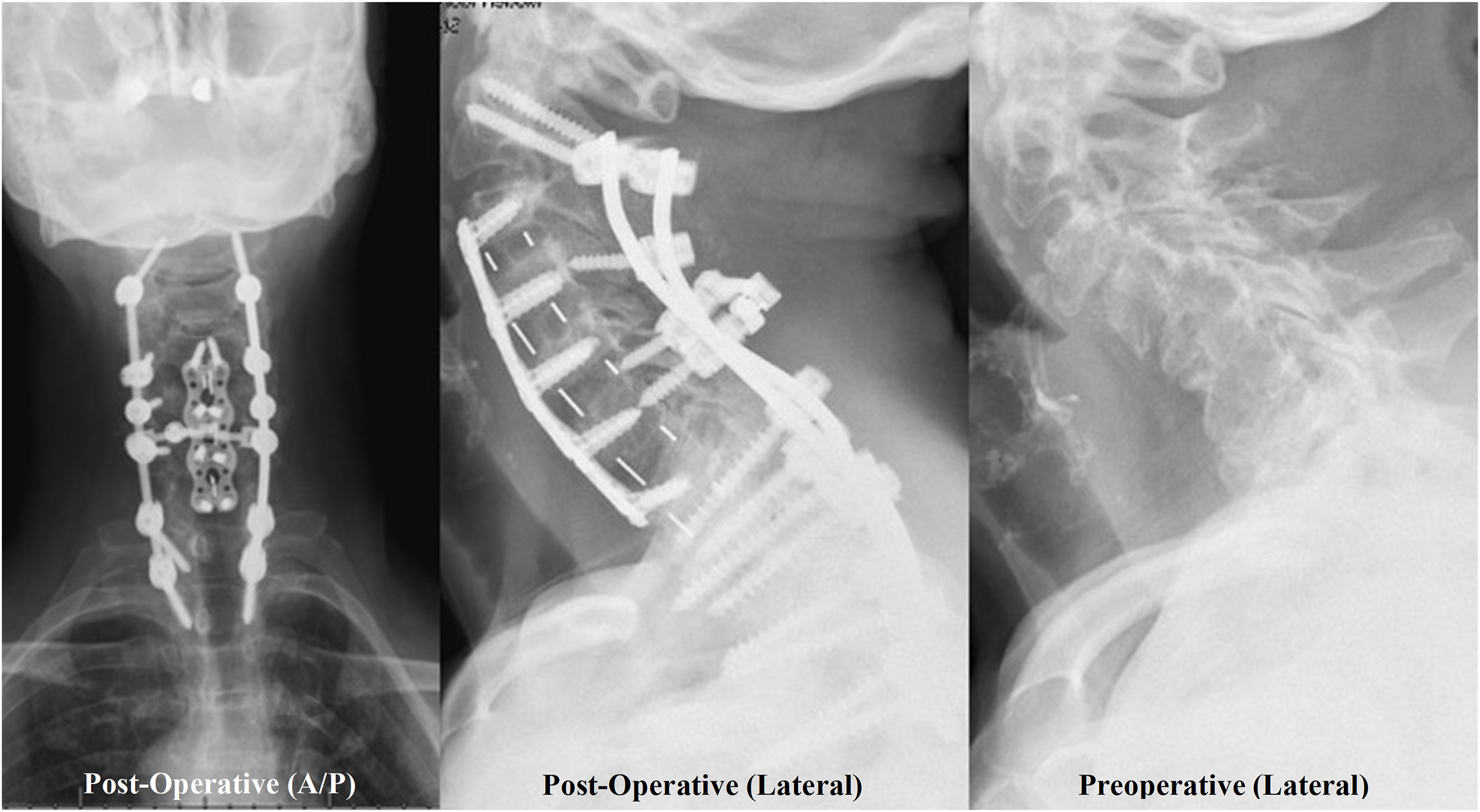
Multiple studies have reported improved biomechanical characteristics of the pedicle trajectory as compared to the lateral mass,5-7 and this trajectory may have particular applications in trauma or deformity cases where a very rigid construct is necessary.8,9 In addition, the lateral-to-medial trajectory of the screw means that the screw tulip will be oriented more laterally than that of a lateral mass screw. This tulip position facilitates rod passage down into thoracic pedicle screws, where rod contouring to a medially based lateral-mass tulip head is more challenging (Figure 3), and also in minimally invasive techniques where the laterally based skin incisions make placement of a lateral mass screw difficult.
10
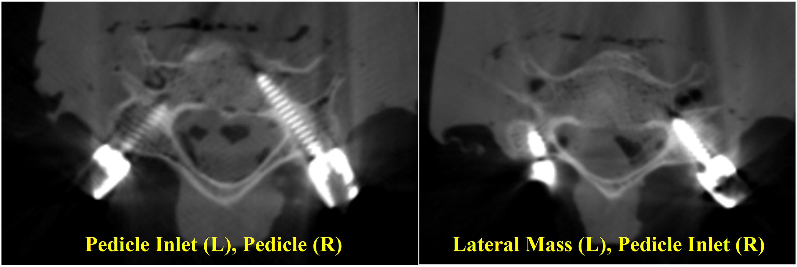
Representative images for the (a) Lateral Mass trajectory and the Pedicle Screw trajectory (b), with the Pedicle Inlet Trajectory represented by the reduced depth of insertion to the red stops before the isthmus of the Pedicle in (b). Because the screw does not have to directly in line with the pedicle, the starting point for the pedicle inlet trajectory can be more varied than for a true pedicle screw (green lines). Intra-operative CT image of Lateral Mass (LM), Pedicle Inlet (CPI), and Pedicle (CP) trajectories. Preoperative (left) and post-operative (center) lateral radiographs showing pedicle inlet screws placed at C4-6 with the screw tip stopping short of the vertebral body. Post-operative AP (right) image showing pedicle inlet screw tulips in line with the thoracic pedicle screws for ease of rod placement.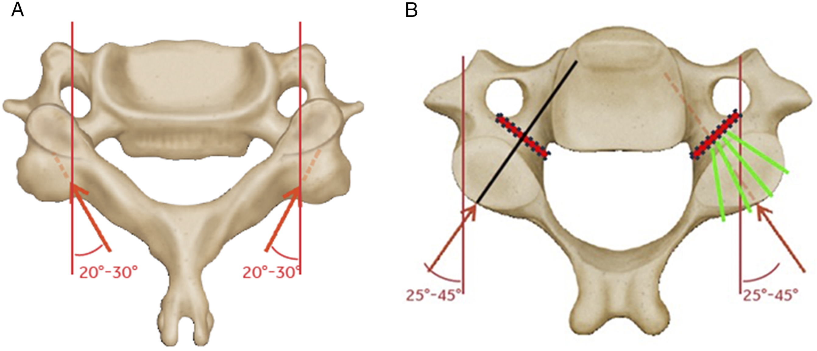
In spite of the improved fixation offered by pedicle screws, concerns over possible risks to the neurovascular anatomy have limited widespread adoption.11,12 Studies on pedicle screws placed using anatomic technique have reported malposition rates of up to 43%. 13 The use of navigation assistance, 13 and intra-operative CT assessments 14 can improve accuracy, but even with navigation the malposition rate remains elevated compared to lateral mass fixation with much greater concern from the clinical sequelae of neurologic or vascular injury.13,15
In this study, we propose a novel trajectory for navigated instrumentation in the sub-axial cervical spine that we have called the pedicle-inlet screw. 16 The screw trajectory is similar to that of a pedicle screw and similar to previous paravertebral foramen screws,17,18 but the tip of the screw stops short of the pedicle isthmus, thus limiting the risk to the neurovascular structures, while maintaining the lateral tulip-head position that facilitates rod passage down to the thoracic spine and minimally invasive approaches where needed (Figures 1 and 2). We hypothesized that the dense bone at the pedicle entry would allow the pedicle inlet screws to demonstrate improved biomechanical characteristics as compared to traditional lateral mass screws.
Methods
Surgical Technique
Fresh human spines were procured, immediately sealed in double plastic bags, and frozen <0°C. Each specimen was imaged to identify anatomic abnormalities. Specimens with a history of cancer, fracture, and infection (osteomyelitis/discitis) were excluded if needed Figure 4. Representative image of the pullout test. The spine was embedded on the anterior side and angled on a 3D-rotational mounting plate to align the screw with the load axis for axial pullout.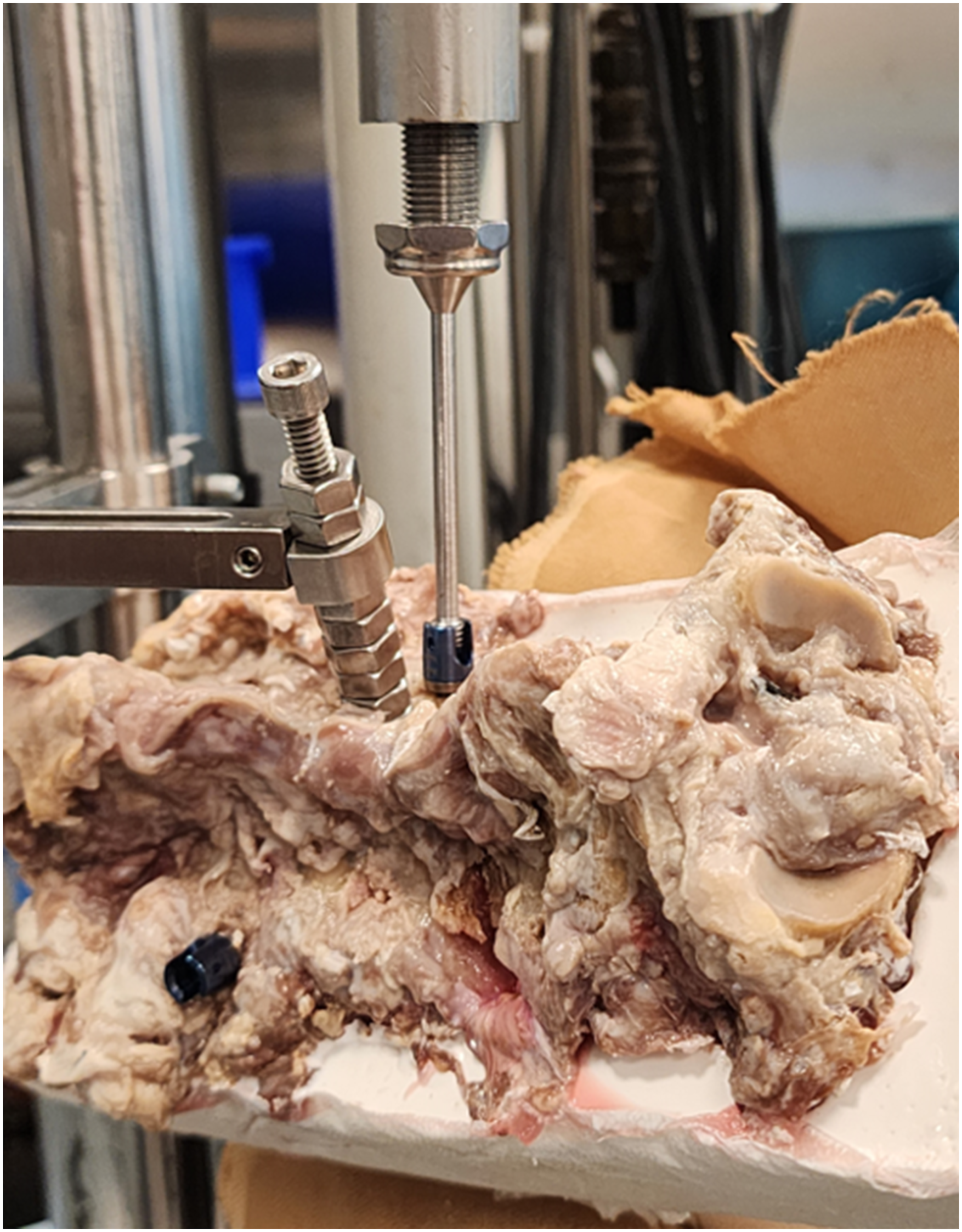
Comparison of Screw Trajectories.
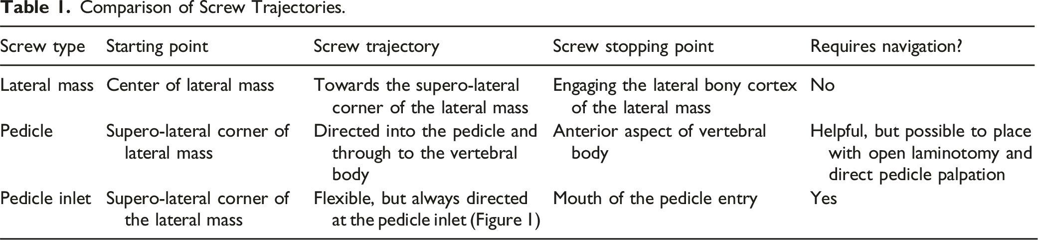
Each insertion was randomized on a per level / per side basis to control for inter-specimen differences in bone quality and anatomy. Screw size, length and diameter, was chosen by the surgeon at the time of implantation based on the specimen’s anatomy, consistent with standard clinical practice and surgical technique for the Infinity™ OCT system multi-axial screws (Medtronic Inc, Minneapolis, MN). 19 A torque-sensing driver was used to measure the maximum value of insertional torque (Nm) during each screw insertion. After all screws were inserted, the spines were then disarticulated and individually wrapped and frozen until mechanical testing.
Biomechanical Testing
Bone screw pull-out testing was conducted per ASTM F-543. 21 The pull-out fixture was secured to the test system actuator, and the specimen secured to the test frame (Figure 3). The superior portion of the screw (head/rod) was clamped by the test fixture attached to the actuator. The test system load cell was zeroed prior to each test. The screws were then pulled in axial tension at a displacement rate of 5 mm/min until the screws are completely pulled from the specimen or until a significant decrease in load occurred. The peak pull-out force was recorded for each test for the pullout strength. Representative photographs were taken in order to document the test set-up (Figure 3).
Statistical Allocation and Analysis
Sample size was estimated from a prior published cadaveric study 22 of lateral mass vs pedicle screw pullout. With ANOVA power analysis (G*Power23,24) for repeated-measures and variance estimated from the prior study, we assumed that the pullout strength of the pedicle inlet trajectory would be greater than lateral mass but less than or equivalent to the pedicle trajectory, and calculated the effect size of comparing the three groups for 85%–90% power with n = 18 specimens. With three groups and two sites per vertebra, the screws were allocated in guidance with a randomized block design across the specimens for a total of 180 insertions. In the case of bony anatomy that was inappropriate for a given trajectory (eg, small pedicle width at a specific level), surgeon discretion was used to dictate the clinically representative scenario to implant on the contralateral side or change adjacent levels. These changes were recorded in the achieved allocation.
Repeated-measures ANOVA (mixed effects model, Minitab 25 ) was performed with random factors for specimen and surgeon and trajectory as the fixed factor to allow for comparisons within the same vertebra or cadaveric spine. Statistical significance was set at α = 0.05. The randomized allocation of screws was across all the specimens regardless of anatomy or bone quality, in that all-comer data was incorporated into the statistical design. The randomization included specimens that might be considered both low and high bone quality.
Specimens
Demographics and Biomechanical Results.
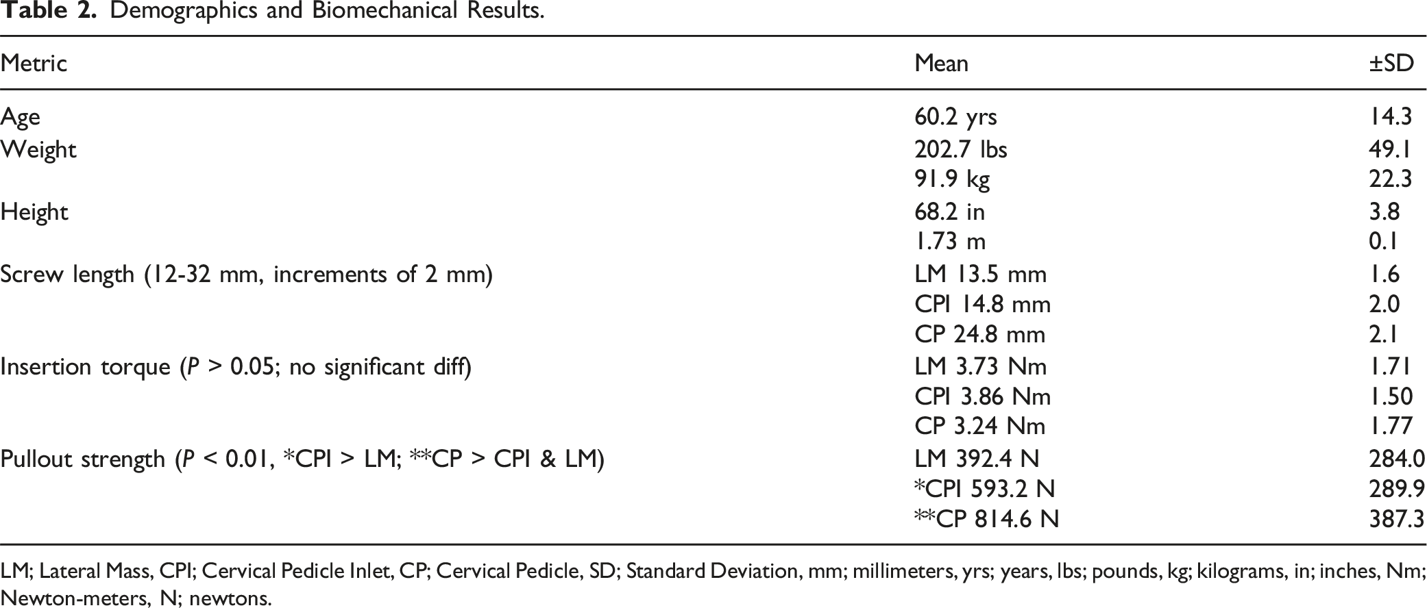
LM; Lateral Mass, CPI; Cervical Pedicle Inlet, CP; Cervical Pedicle, SD; Standard Deviation, mm; millimeters, yrs; years, lbs; pounds, kg; kilograms, in; inches, Nm; Newton-meters, N; newtons.
Imaging Review
After surgical implantation, each specimen was imaged with a CT scan and the images were then reviewed by a fellowship trained spine surgeon to identify any instances of implant malposition. The imaging review was conducted before biomechanical testing.
Results
Screw Lengths
Mean screw length for the lateral mass trajectory was 13.5 mm (SD 1.6 mm, range of 12-18 mm), for the pedicle inlet trajectory was 14.8 mm (SD 2.0 mm, range of 12-18 mm) and for the pedicle trajectory was 24.8 mm (SD 2.1 mm, range of 20-32 mm) (Figure 5). There was no significant difference in mean lengths of the lateral mass and pedicle inlet screws (P > .05). Pedicle screws were significantly longer than either of the other trajectories (P < .05 for each comparison). All screws were 3.5 mm in diameter (Table 2). Histogram of screw length in the 18 cadaveric specimens. Pedicle screws had the longest mean screw length (24.8 mm) followed by pedicle inlet (14.8 mm) and lateral mass (13.5 mm) trajectories.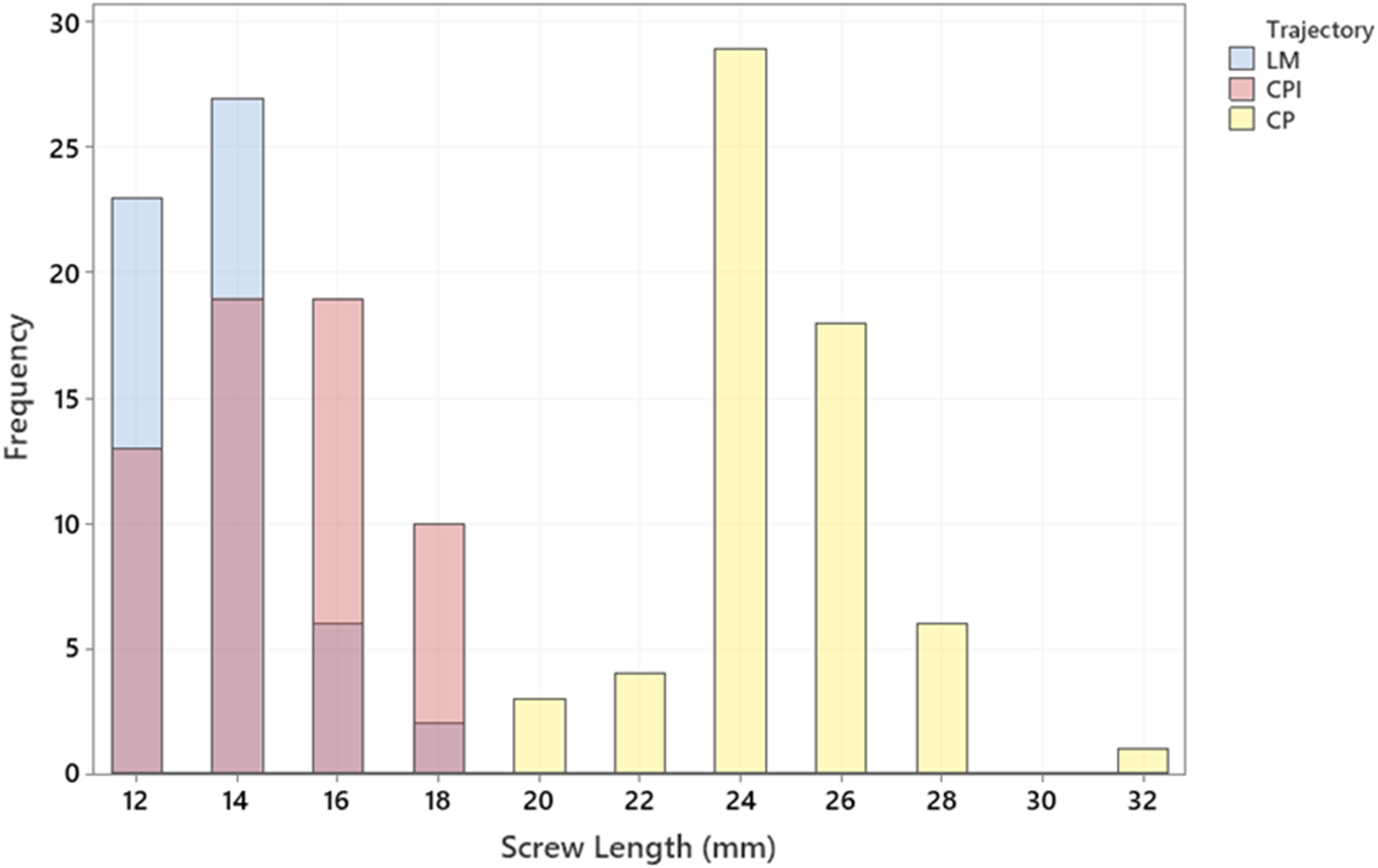
Insertional Torque
There was no significant difference in mean maximal insertional torque between the lateral mass 3.73 Nm (SD of 1.71 Nm), pedicle inlet 3.86 Nm (SD of 1.50 Nm), and pedicle trajectories 3.24 Nm (SD of 1.77 Nm) (P > .05) (Table 2, and Figure 6). Insertion Torque (Nm) for the subaxial screws. There were no significant differences among the three trajectories across n = 18 spines.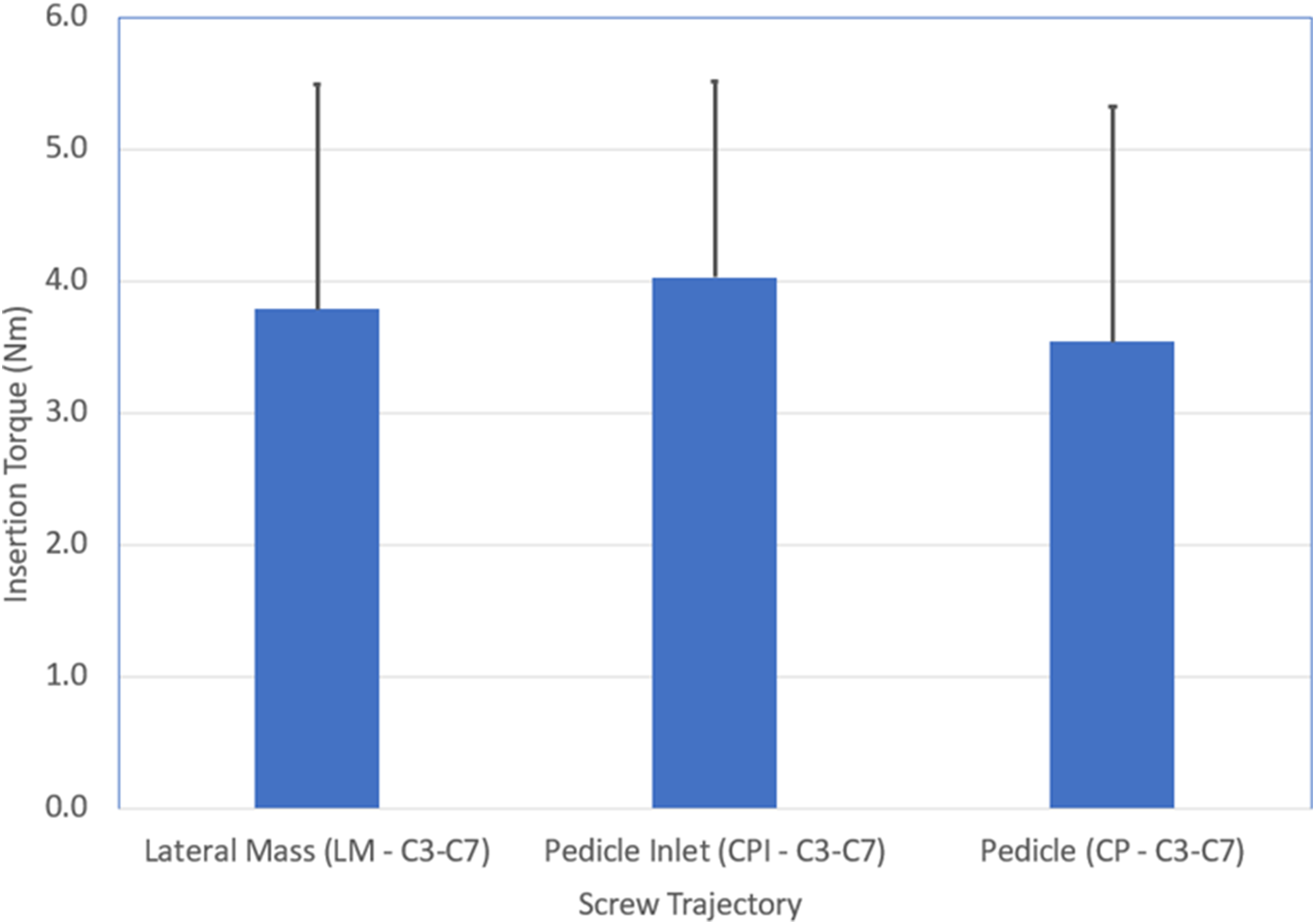
Pullout Strength
The mean pullout strength for the lateral mass screws was 392.4 N (SD of 284.0 N), for the pedicle inlet screws was 593.2 N (SD of 289.9 N), and for the pedicle screws was 814.6 N (SD of 387.3 N) (Table 2). Each inter-group comparison was statistically significant (P < 0.01) with the pedicle screws having a higher pullout strength than either of the other two groups (111% compared to lateral mass and 36% compared to pedicle inlet), and the pedicle inlet having a higher pullout strength than the lateral mass screws by 51% (Figure 7). Mean (+SD) of the Maximum Pullout Force for the subaxial screws. There were significant differences across the three trajectories for n = 18 spines with CP > CPI > LM.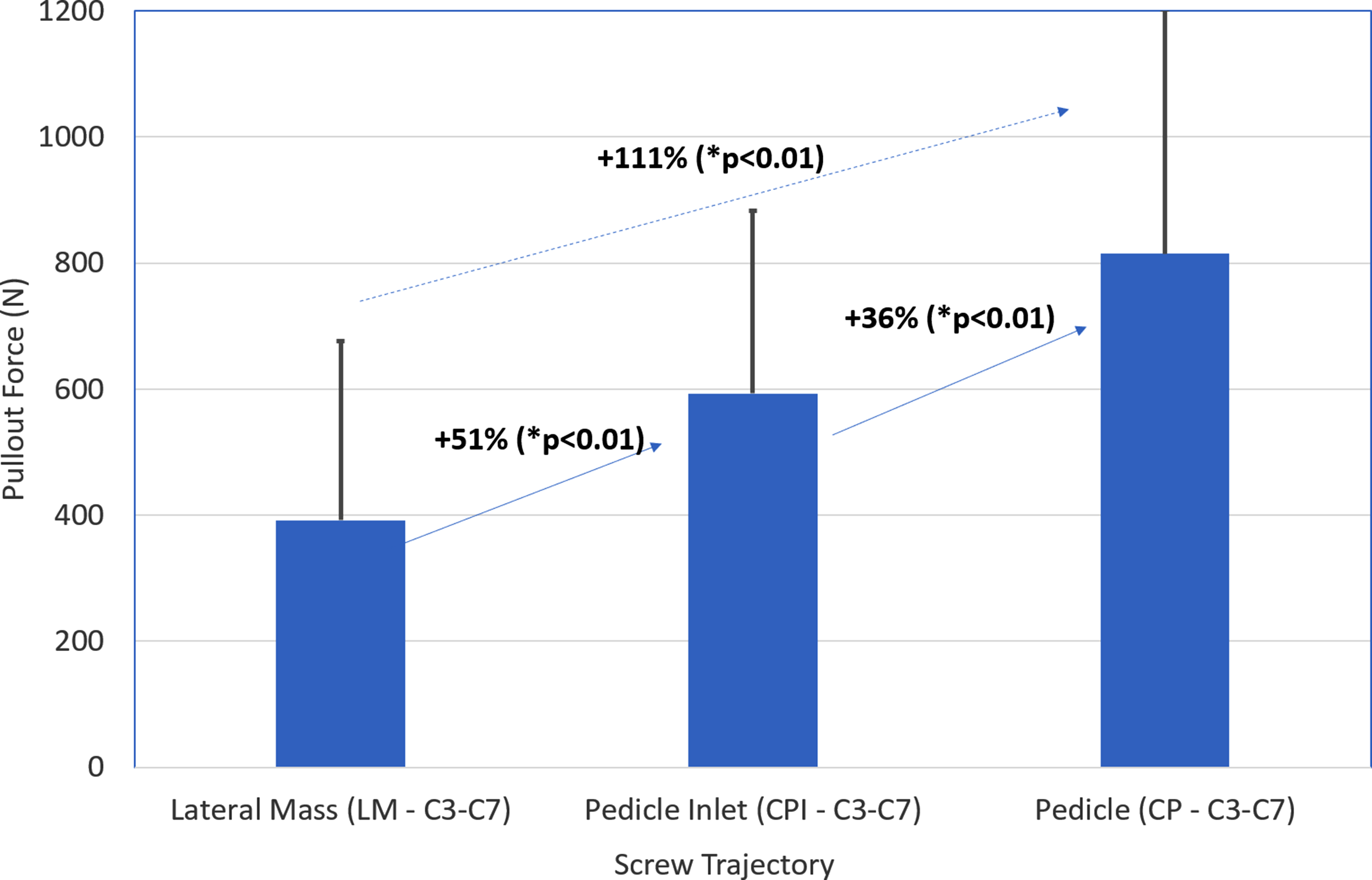
Screw Placement and Imaging Review
The cervical pedicle trajectory had to be aborted in 9 insertions due to inaccessible anatomy for a narrow pedicle or aberrant vertebral foramen. There were no cases where either the lateral mass trajectory or pedicle inlet trajectory was inaccessible. CT scan images were reviewed for each specimen after surgical implantation to verify accuracy. No instances of screw malposition outside of bone were identified in any of the screw trajectories for any specimen.
Discussion
Lateral mass screw fixation is the most widely used method for placement of instrumentation into the sub-axial cervical spine, but with lower pull-out strength and biomechanical characteristics compared to cervical pedicle screws.6,7 However, multiple authors have reported malposition of cervical pedicle screws, which can endanger critical neurovascular structures. 12 Thus, in this study, we proposed evaluating the biomechanical performance of the novel pedicle-inlet trajectory for screw placement, in which the screw start-point and trajectory are similar to that as for a pedicle screw, but the tip of the screw stops short of the pedicle isthmus (Figure 1). Overall, we found similar insertional torque for all three screw trajectories, but improved pull-out strength of the pedicle-inlet trajectory as compared to traditional lateral mass. Several of these findings warrant additional discussion and may be particularly relevant given the increased usage of imaging guidance and minimally invasive techniques for screw placement.
A key consideration for any surgeon placing implants in the cervical spine is the safety of the procedure. The lateral mass trajectory results in the tip of the screw being up and away from the important neurovascular structures, namely the vertebral artery and the cervical nerve root, and as such is widely viewed as a safe method for sub-axial cervical instrumentation. 1 Historically, this trajectory has been found to provide a substantial margin of safety, particularly during free-hand placement of instrumentation where it may be difficult to assess the specific location of the tip of the screw, 2 and particularly in comparison to free-hand pedicle screw placement where implant malposition rates have been high. 13 The increased prevalence of image-guided assistance for sub-axial screw placement has improved the safety profile of cervical pedicle screws, 4 but even with image guidance many cervical pedicles are not accessible, 14 primarily due to variations in patient anatomy such as small pedicle diameter, or aberrancy of the vertebral artery.
One might suggest that a surgeon could pick and choose which level to place pedicle screws, with pedicle screws at favorable levels and lateral mass screws at those with unfavorable anatomy. However, mixing a combination of sub-axial lateral mass and pedicle screw trajectories in the same construct can create difficulties with rod passage due to the offset starting point of the two screw-tulips (Figure 8). Thus, there is a need to have an alternative screw trajectory for use in cases where the pedicle trajectory is not feasible, but the surgeon desires increased biomechanical purchase compared to what is available with a lateral mass construct. In this study, we found 9 instances where a planned pedicle screw trajectory had to be aborted due to inaccessible anatomy, even with the use of image guidance. However, there were no instances where the pedicle inlet trajectory had to be aborted, and a post-implantation review of CT scans showed no cases of screw malposition. Therefore, although not the primary aim of our study, we suspect that the placement of navigated pedicle inlet screws is likely to be a safe and viable alternative to lateral mass screw fixation in many patients. We do not advocate attempting free-hand placement of pedicle inlet screws, but limited clinical case series of this technique using navigation guidance have previously been published,
16
and our group plans further validation of the safety profile of this technique in future clinical and cadaveric studies. Representative image of a specimen with randomized screws placed, indicating the lack of alignment across screwheads.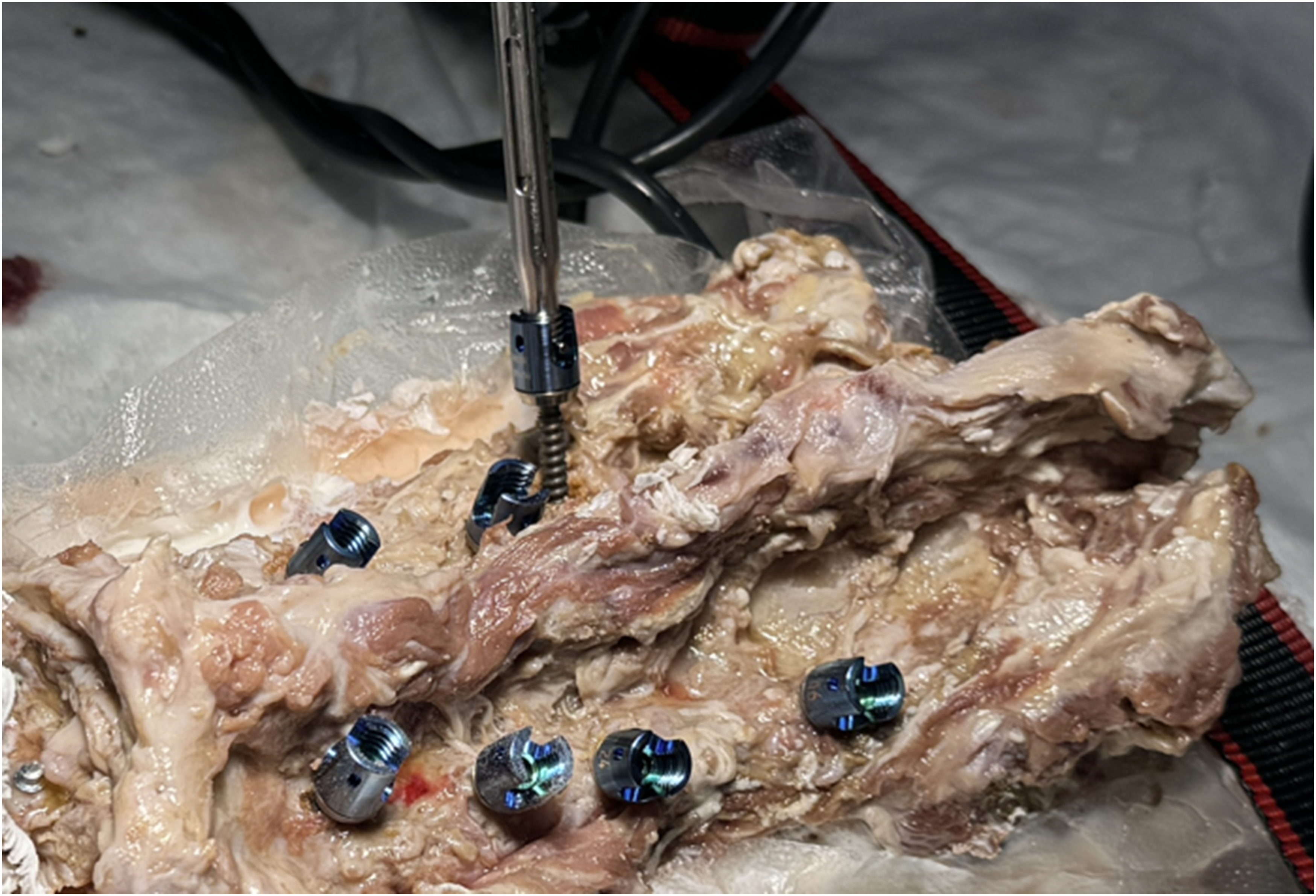
As would be expected given the anatomy of each trajectory, the average screw length of the cervical pedicle screw was higher than for either of the other trajectories (Figure 5). This increased bony purchase likely contributes to the screw’s biomechanical advantage, and consistent with other published studies,6,7 we found that the cervical pedicle trajectory had the highest pull-out strength (Figure 7) (P < .01 for each comparison). The lateral mass trajectory results in the tip of the screw being placed into cancellous bone. This bone is typically of poor quality, and our finding that the lateral mass trajectory had the lowest pull-out strength is also consistent with existing literature.6,7 In contrast, the pedicle inlet trajectory results in the tip of the screw being placed into the dense bone at the isthmus of the pedicle entry (Figures 1 and 2). This bone is typically among the densest areas of the sub-axial vertebrae, and we found that the pull-out strength was 51% higher for the pedicle inlet screws as compared to lateral mass (593.2 N v 392.4N, P < .01) (Figure 7). As noted in our methods, to avoid bottoming out the screw and stripping the threads, we suggest tapping through the entire length of the planned screw trajectory. There was no difference in mean screw length between lateral mass and pedicle inlet trajectories, and thus screw length alone cannot explain the improved performance of the pedicle inlet cases (Figure 5).
Similar to prior published studies that compared lateral mass and pedicle screws, 26 we found no difference in insertional torque between the three screw trajectories (P > .05 for each comparison). The reason for this is not clear, particularly given that studies in the lumbar and thoracic spine have correlated insertional torque and pull-out strength for pedicle screws. 27 We recorded insertional torque on the final 1-3 turns of the driver as the screw was implanted. It is possible that peak insertional torque occurred earlier during implantation. Another explanation could be that some readings were recorded once a screw head tulip was against bone which would not reflect true differences in torque during peak insertion across various methods. Alternatively prior authors have suggested that the smaller anatomy of the cervical spine and generally increased density of the cervical vertebrae relative to thoracic and lumbar cases serve to minimize the impact of bone quality on insertional torque in cervical cases. 26 In this study, we did not obtain DEXA scans or specifically report on the bone mineral density of the specimens. However, we attempted to control for this using a randomized allocation of screws across specimens.
Minimally invasive approaches to the cervical spine have recently been reported using lateral skin incisions to allow for the percutaneous placement of screws along a pedicle trajectory. 20 Because the skin incision is laterally based, it is difficult to place a lateral mass screw which requires a medial-to-lateral alignment. Thus, the reported series have typically utilized a true full pedicle trajectory with placement of the screw all the way into the vertebral body.10,28 For the reasons cited above, some surgeons have expressed concern about placement of these screws, particularly given that a percutaneous approach, by its very nature, limits visualization of the anatomic reference points available to help verify screw accuracy during placement. We believe that the results presented here should support the pedicle-inlet trajectory as an alternative strategy that may have particular relevancy in these navigated minimally invasive cases where lateral mass screws cannot be placed. 10
Traditional lateral mass screws can safely be placed using a free-hand technique because the trajectory is directed laterally and away from important neurovascular structures. True pedicle screws can be placed using a free-hand technique, but this is uncommon in the sub-axial cervical spine where the pedicles are typically small. More commonly, pedicle screws require navigated assistance, or the completion of a laminotomy to allow palpation of the pedicle borders to guide placement. In contrast, it is our recommendation that pedicle inlet screws be placed solely with navigation assistance. Navigation will allow the surgeon to safely target the screw tip towards the pedicle inlet and choose an appropriate length screw. Because this anatomy cannot be directly palpated or visualized with open techniques or fluoroscopy, navigation is necessary to safely place this screw type. Surgeons who do not have access to navigation at their hospital should not place this screw.
In summary, we believe the pedicle inlet screw has several advantages. First, the screw can be placed with a starting point in line with the pedicle trajectory. This places the screw tulip in-line with any pedicle screws that are placed in the construct, and fascilitates rod passage at the end of the case, particularly in cervico-thoracic constructs where thoracic pedicle screws are present and passage of a rod from a lateral pedicle screw tulip at T1 to a medially oriented lateral-mass tulip at C6 or C7 can be difficult. Second, in the sub-axial cervical spine the pedicles are often of very small diameter and it is not feasible to place a true pedicle screw. The pedicle inlet screw offers a biomechanically superior option compared to lateral mass screws in this common clinical scenario. Third, because the pedicle inlet tulip head is laterally oriented, it is easy to do midline decompressive work after the screw has been placed. This is in contrast to a lateral mass screw where the medially oriented tulip head can block access for laminectomy and foraminotomy work. Fourth, minimally invasive screw placement techniques have been described, and these require a paramedian incision. Lateral mass screws cannot easily be placed through this incision because of their medial-to-lateral trajectory, and pedicle inlet screws are much simpler to use in these approaches. Fifth, prior studies on pedicle screws have shown high rates of cortical breaches, particularly in the sub-axial spine. Because the pedicle-inlet screw stops short of the pedicle, there should be less risk of neurovascular injury, and indeed no cortical breaches were observed in this study using the pedicle inlet technique and navigation assistance. Finally, the increased biomechanical characteristics of the pedicle inlet screw, relative to the lateral mass screw, may allow surgeons to apply additional corrective forces to the construct, while still minimizing implant failure risk.
Overall, we found that the pedicle inlet trajectory resulted in a 51% increase in pull-out strength compared to the lateral mass trajectory, with no cases of screw malposition or need to abort intra-operative screw placement due to patient anatomy. Further clinical and cadaveric studies are planned to define the anatomic and safety profiles of this novel screw trajectory.
Footnotes
Acknowledgements
We gratefully appreciate the use of Medtronic research laboratory facilities (Memphis, TN) and the management and engineering contributions of Brian Murrell, Larry McBride, and Rex Armstrong.
Declaration of conflicting interests
The author(s) declared the following potential conflicts of interest with respect to the research, authorship, and/or publication of this article: Each of the authors discloses that Martin, Bhowmick, Rossi, Coric, Pham receive consulting fees from Medtronic. Schweitzer, Woods, and Rawlinson are employees of metronic.
Correction (July 2025):
This article has been updated to correct the expansion of “nm” in Table 2 to “Newton-meters.”
Funding
The author(s) disclosed receipt of the following financial support for the research, authorship, and/or publication of this article: The cadaveric specimens and fascilities for testing were provided by Medtronic.