
Abstract
Study design
In vitro human cadaveric biomechanical analysis.
Objectives
Optimization of prostheses for cervical disc arthroplasties (CDA) reduces the risk of complications. The instantaneous helical axis (IHA) is a superior parameter for examining the kinematics of functional spinal units. There is no comprehensive study about the IHA after CDA considering all 3 motion dimensions.
Methods
Ten human functional spinal units C4-5 (83.2 ± 7.9 yrs.) were examined with an established measuring apparatus in intact conditions (IC), and after CDA, with 2 different types of prostheses during axial rotation, lateral bending, and flexion/extension. Eccentric preloads simulated strains. The IHA orientation and its position at the point of rest (IHA0-position) were analyzed.
Results
The results confirmed the existing data for IHA in IC. Lateral preloads showed structural alterations of kinematics after CDA: During axial rotation and lateral bending, the shift of the IHA0-position was corresponding with the lateral preloads’ applied site in IC, while after CDAs, it was vice versa. During lateral bending, the lateral IHA orientation was inclined, corresponding with the lateral preloads’ applied site in the IC and oppositely after the CDAs. During flexion/extension, the lateral IHA orientation was nearly vertical in the IC, while after CDA, it inclined, corresponding with the lateral preloads’ applied site. The axial IHA orientation rotated to the lateral preloads’ corresponding site in the IC; after CDA, it was vice versa.
Conclusion
Both CDAs failed to maintain physiological IHA characteristics under lateral preloads, revealing a new aspect for improving prostheses’ design and optimizing their kinematics.
Keywords
Introduction
Cervical disc arthroplasty (CDA) has consistently been proven to have superior long-term results regarding functional outcome, pain reduction, patients’ satisfaction, and rate of adjacent segment disease (ASD) compared to anterior cervical discectomy and fusion (ACDF).1–3 Besides the numerous clinical data, biomechanical studies and finite element analyses have intensely analyzed various implants.4–13 Ultimately, most of the studies showed a basic restoration of the physiological motion pattern. In comparison to intact conditions (IC), significant but rather unspecific differences could be observed under certain conditions, depending on the prosthesis design and model. Hereby, compressive preloads influence prostheses’ motion patterns, and the combined motion kinematics play an important role. 14 In a mismatch, for example, due to an altered center of rotation after CDA, altered kinematics can result in an uncinate impingement and abnormal facet joint contact, particularly under lateral strains. 9 According to Patwardhan and Havey (2020) 9 , a lower center of rotation after CDA allows the cranial vertebral body of a segment to swing differently. Under lateral bending, this would result in an immediate impingement with the uncinate process, while under flexion/extension a displacement of the center of rotation would not lead to abnormal joint contact immediately, as there is no uncinate process. This may cause the development of ASD or adjacent segment ossification after CDA.15,16
While many parameters can serve to examine the motion kinematics of a functional spinal segment (FSU), the most accurate parameter for the evaluation of the cervical spine’s intervertebral motion appears to be the instantaneous helical axis (IHA). 17 Anderst et al (2016) and Jonas et al (2018)18,19 have precisely described the intervertebral kinematics of the cervical spine for all 3 motion dimensions under functional loading in intact conditions (IC). Both studies represent reference data and show the importance of reporting motion analyses for all motion dimensions.
To reduce the unphysiological kinematics that might result in ASD, IHA analyses can deepen the understanding of a motion mismatch after CDA. To the best of our knowledge, no study has shed light on IHA alterations after CDA, focusing on lateral strains and preloads in a comprehensive way for all 3 motion dimensions. Thus, the aim of this study was (1) to confirm existing reference data for the IHA in the FSU C4-5 in IC in all three motion dimensions, (2) to examine kinematical alterations in the FSU C4/5 after two different types of CDA, and (3) to search for structural alterations after CDA, particularly under lateral preloads.
Materials and Methods
Specimens
The study was approved by the institutional review board of the University of Göttingen (Ethics Committee Göttingen, approval number 18/03/18). Informed consent was not necessary. The body donors had, during their lifetime, bequeathed their bodies to the Center of Anatomy at the University of Göttingen, which presupposes the unrestricted capacity of the donor to consent. Ten human FSUs C4-6 (8 women, 2 men; 83.2 ± 7.9 yrs.) were extracted from donors. Computed tomography (CT) scans were performed to exclude specimens with osteochondrosis or spondyloarthritis above grade I according to Kellgren and Lawrence
20
or injury. After extraction, soft and muscular tissues, vessels, and neural structures were removed from the specimens, leaving the ligaments and capsules intact. The specimens were directly frozen at -20°C until the start of the experiment. After thawing, C5 and C6 were fixed with screws. Next, the specimens were imbedded in brackets using screws and a cold polymerizate (Weitur-Press Standard, Weithas, Lütjenburg, Germany) (Figure 1). For embedding, the upper endplate of the subjacent vertebra and the lower endplate of the superjacent vertebra were horizontally aligned to the brackets using fluoroscopy. Sagittal orientation was achieved using a line running through one point in the middle of the spinous process and another in the middle of the vertebra. Coronal alignment was performed by placing the vertebra’s posterior wall in the middle of the bracket. The first experimental run started in IC. Afterwards, an experienced spine surgeon, who was not involved in further steps of the study, performed an implantation of 1 of 2 prostheses: the CDABaguera (Baguera C, Spineart, Plan-les-Ouates, Switzerland) and the CDARhine (Stryker, Cervical Disc Replacement System, Kalamazoo, Michigan, USA) according to the manufacturer’s instructions. These 2 types were chosen because of their structural design differences. The CDABaguera is a three-part prosthesis with a stable and compact design consisting of titanium upper and lower plates with a polyethylene core in between. The polyethylene core was clipped into the base plate and built with controlled mobility to avoid excessive restriction of the facet joints. This type reflects the typical design of a ball-and-socket prosthesis. The curvature of its surface is designed to adapt to axial rotational movements. The base plate and core allow for elastic deformation of shocks and vibrations. The CDARhine is a non-articulating monoblock prosthesis with an elastomer-polyurethane core designed to mimic the mechanical properties of an intact intervertebral disc in terms of its size. It is surrounded by 2 end plates, both of which are domed and rounded to adapt to the disc space and are equipped with a central keel to ensure primary fixation.
5
The size of the disc was chosen according to the CT scan. After the second experimental run, the prosthesis was explanted, and the second prosthesis was implanted. Stratification was performed for implant selection in such a way that each of the 2 CDAs was performed first in five out of ten of the specimens (Sealed Envelope, Clerkenwell Workshops, London, UK). During the experiment, the specimens were moistened regularly to avoid them drying out. Specimens: Coronal (A) and sagittal (B) X-ray view of specimens. The screws anchor the specimens to their fixtures.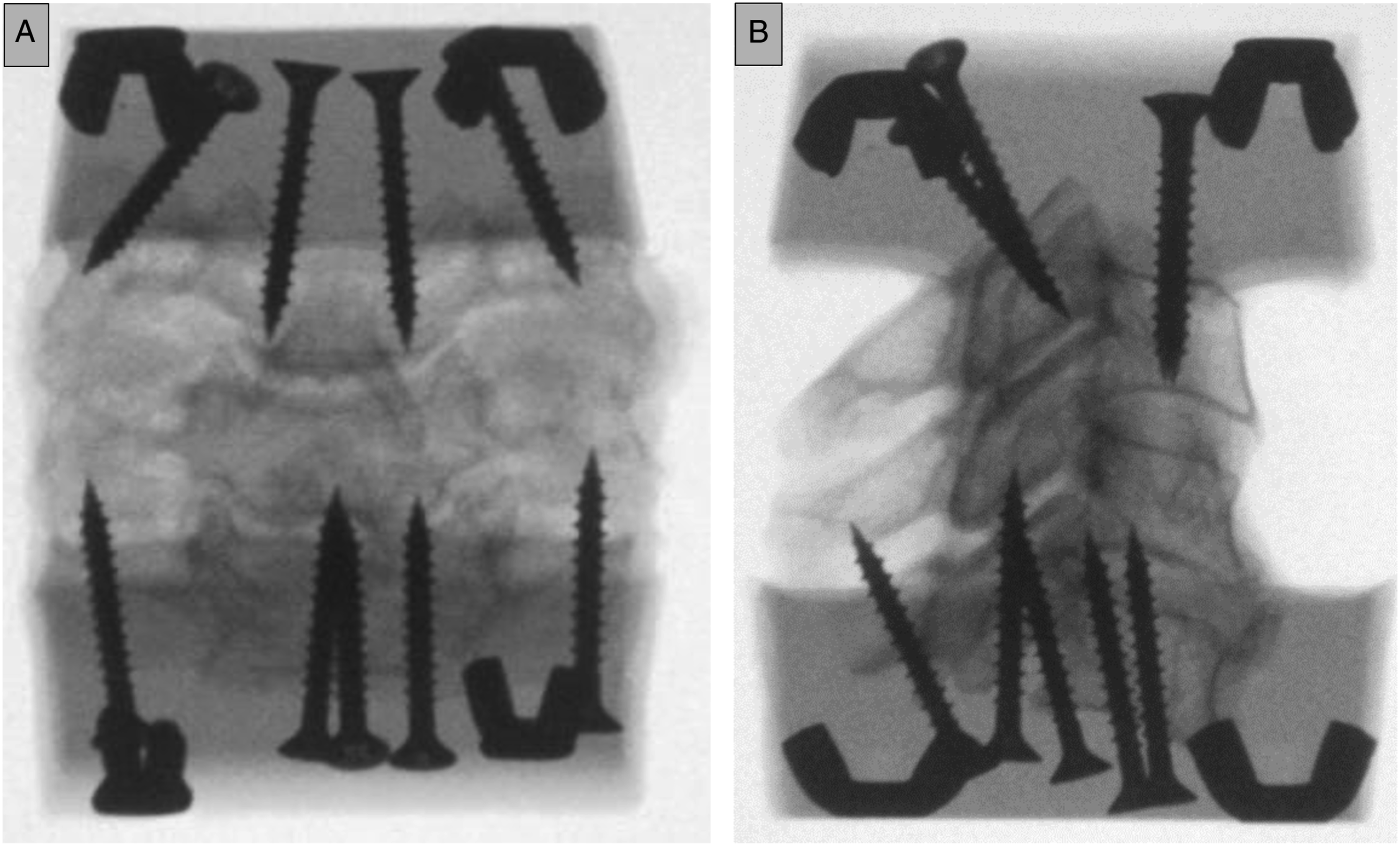
Testing Apparatus
An established 6D measuring apparatus was used for the experiments.10,12,21 Since a detailed description of the apparatus was recently published,10,21,22 only a brief overview is presented (Figure 2). The apparatus can determine the position of the IHA with a fidelity of ± 1 mm for axial rotation, lateral bending, and flexion/extension of .02°.
22
The apparatus allows the application of cyclically varying torque on the mobile superjacent vertebrae C4 using a water pump system. Shiftable preloads on the Y- or X-axis with different axial forces (Fz) and positions were added to simulate the biophysical interplay of muscles under the weight of the head (Fz: central [10 N/50 N], ventral or dorsal [50 N, ± 30 mm], and lateral [left or right] [50 N, ± 30 mm]). The average head weight was approximated at 5 kg.
23
Under bending of the neck and eccentric movement of the head, the forces on the cervical spine will be much higher than 50 N.
24
The preload weight of 50 N was chosen based on the test runs, in which higher loads (above 80-100 N) resulted in undynamic movements of the FSUs. For each condition (IC, CDABaguera, and CDARhine), experimental runs were performed with each preload (central (10 and 50 N), ventral, dorsal, left, right). The preload application was stratified (Sealed Envelope, Clerkenwell Workshops, London, UK). In total, 18 runs were performed for each FSU. Six inductive displacement sensors recorded the movement of the mobile superjacent vertebra (Millimar 1310 inductive probe, Mahr GmbH, Göttingen, Germany). The Z-axis is defined by the Fz-line, which runs through the center of resistance. This is defined as the point where the deflection of the horizontal displacement sensors was least and was determined once for each segment, serving as a reference for all further runs.10,21 The axes were defined as depicted in Figure 2. Measuring apparatus: (A) The model of the 6D measuring apparatus is depicted. Six inductive displacement sensors were arranged in a 3-2-1 configuration. Balancing weights were used for neutralization of the weights. The force system was applied via a turnstile. Shiftable preloads on the Y- or X-axis served as a simulation of physiological interplay (Fz: central (10 N/50 N), ventral or dorsal (50 N, ± 30 mm), and lateral (left or right) (50 N, ± 30 mm). The torque was triggered by water being pumped from reservoir A to reservoir B, and vice versa. (B) Photograph of the laboratory setup of the 6D measuring apparatus.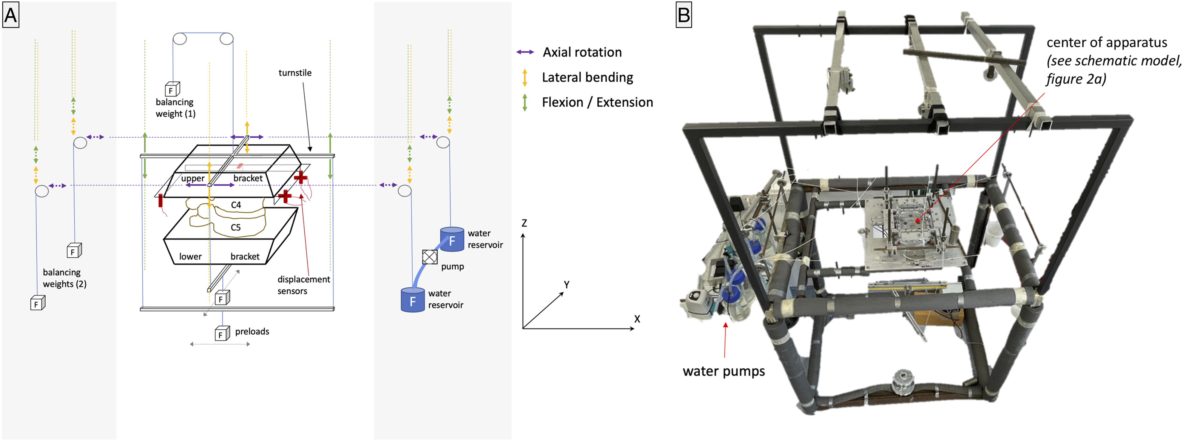
Mathematical Model of the Apparatus
The spatial movement of a coordinate system linked to the mobile superjacent vertebral body was captured by the six displacement sensors. The calculation of the IHA was performed using a modified version of the direct approach method. 22 As discussed in earlier works,10,21 it was chosen due to its high accuracy in calculating the intersection points of the helical axis with the plane of interest. Nevertheless, compared to the singular value decomposition approach or the triad method, a greater error in determining the axis and angle of rotation is expected. 25 The full algorithm of the direct approach method was recently published.10,21
Parameters
The entire range of motion (ROM) in each motion dimension covered 3 to 5. However, to address physiological motions, only a small range of motion (ROM) was chosen for the data analysis
Statistics
Due to the presence of nonparametric data, the Friedman test was applied for paired observations. Post hoc tests were performed using the Dunn-Bonferroni approach. The level of significance was set at P < .05. SPSS Statistics software version 27.0 (IBM SPSS Inc., Chicago, IL, USA) was used. For nonparametric data, medians are used for presentation in the manuscript. The interquartile range is not presented in the tables for clarity. The full tables with medians and interquartile ranges are included in the supplementary data.
Results
Axial rotation
IHA Migration
For axial rotation, the IHA migration of one specimen for a full ROM is depicted in Figure 3. Under both the central preloads and the ventral preload, the entire path length was significantly shorter after the CDABaguera than in the IC. Under a 50 N central, dorsal, and ventral preload, the entire path length was significantly shorter after the CDARhine than in IC. Furthermore, after a 50 N central preload, the total path length was significantly shorter after the CDABaguera than after the CDARhine (Table 1a). IHA migration in full range of motion: Under the 10 N central preload, the IHA under IC migrated from one facet joint to the other, forming a U-curve at the anterior part of the vertebral body. The left axial rotation led to a shift to the left and a right axial rotation to the right (3.1a). The IHA migration was compressed under a 50 N central preload (3.1b). A dorsal preload resulted in flattened IHA migration at the posterior wall of the vertebral body (3.1c), while under a ventral preload, the IHA formed an O-like curve running along the vertebral body’s wall and ending close to the middle of the posterior wall at the spinal canal (3.1d). The left and right preloads distinctly flattened the IHA migration and shifted it to the corresponding site (3.1e, f). After both TDAs, the IHA migration appeared compressed under central, ventral, and dorsal preloads, while lateral preloads increased the IHA migration, particularly on the opposite site of the applied preload (3.2a-f). IHA Parameters During Axial Rotation. asignificant vs IC. bversus CDABaguera. cversus CDARhine (Dunn-Bonferroni post hoc test, p < .05). See supplementary data for complete tables with interquartile ranges.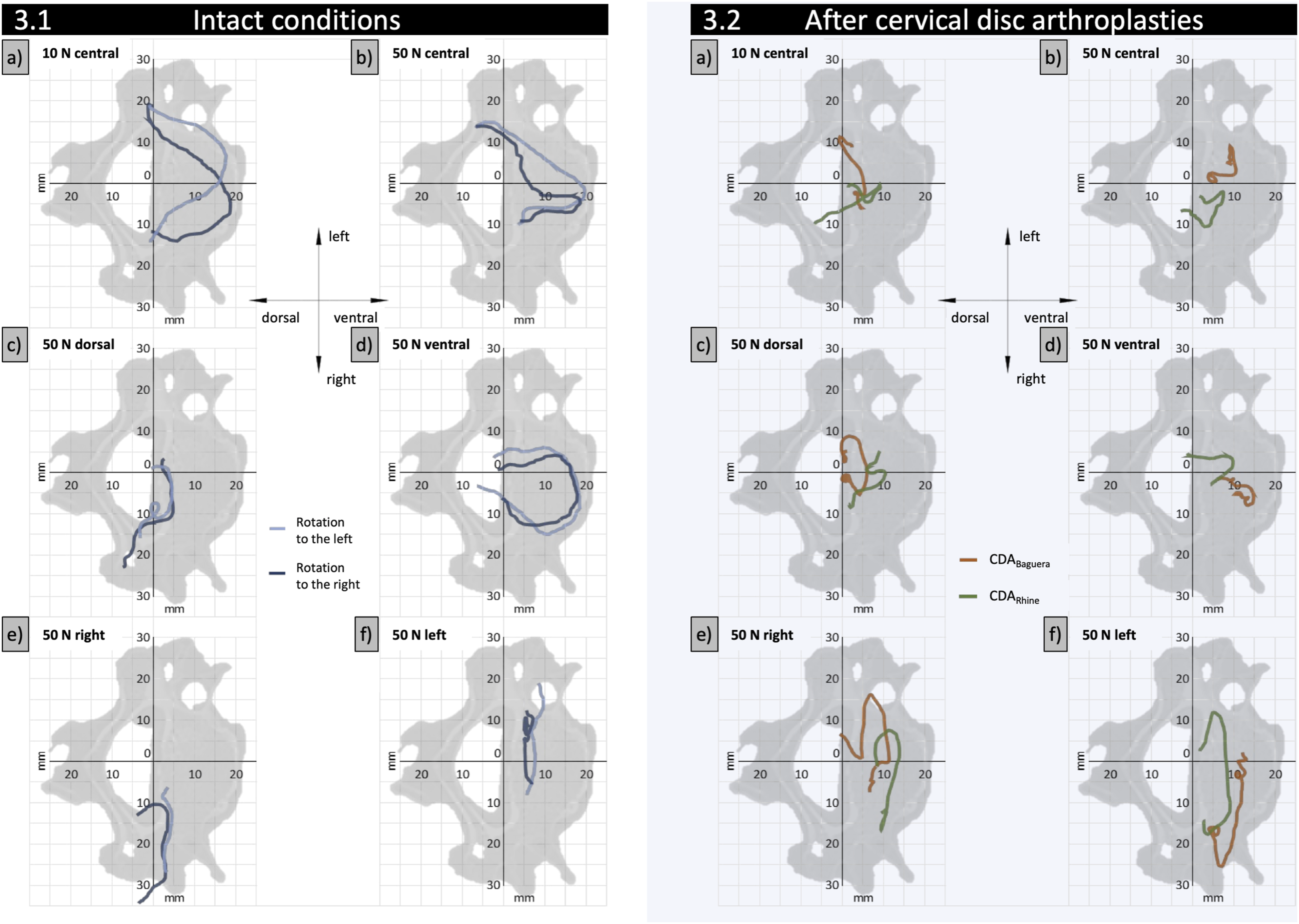
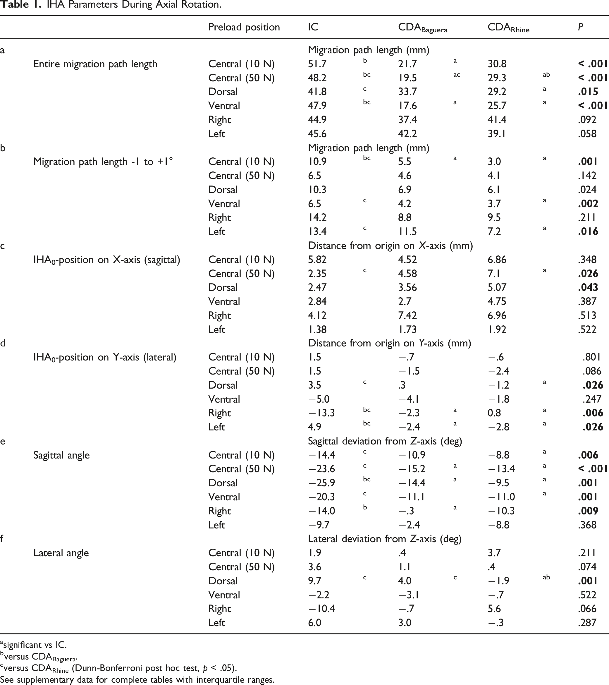
Regarding the range of γ ± 1.0°, the path length of both CDAs was significantly shorter than that of the IC under a 10 N central preload. Furthermore, the path length of the CDARhine was significantly shorter than that of the IC under a ventral and a left preload (Table 1b).
IHA0-Positions
The IHA0-positions were located at the medial posterior part of the vertebral body. Regarding the sagittal shift, under a 50 N central preload, the IHA0-position of the CDARhine was significantly more anterior than in the IC. Regarding the lateral shift, eccentric preloads influenced the IC, while they had little impact on the CDAs. A dorsal preload resulted in a significant leftward shift of the IHA0-position under IC compared to the CDARhine. Under IC, lateral preloads led to a shift in the IHA0-positions to the corresponding site that was significantly different from both CDAs (Table 1cd) (Figure 4A). IHA0-positions and orientations for axial rotation: (A) The IHA0-positions and IHA migration paths for all FSUs are depicted during axial rotation. The coordinates of the IHA0-positions (axial plane) are plotted for rotation to the left (-1°), point of rest (0°), and rotation to the right (+1°). The rotation is represented by color strength (rotation to the left [-1°] with full color strength, point of rest [0°] with medium color strength, and rotation to the right [+1°] with light color strength). The IC are represented with a square (■), the CDABaguera with a triangle (▲), and the CDARhine with a dot (●). The IHA coordinates at -1°, 0°, and +1° were quadratically polynomially regressed and are presented in bold lines. The average IHA migration paths for -1° to +1° axial rotation are depicted in black in the axial plane. (B) The IHA orientations of the IC, the CDABaguera, and the CDARhine are depicted for axial rotation. Different preloads are represented in color. In particular, the different IHA orientations in the IC and after the CDABaguera under lateral preloads (right [yellow] and left [blue]) are emphasized.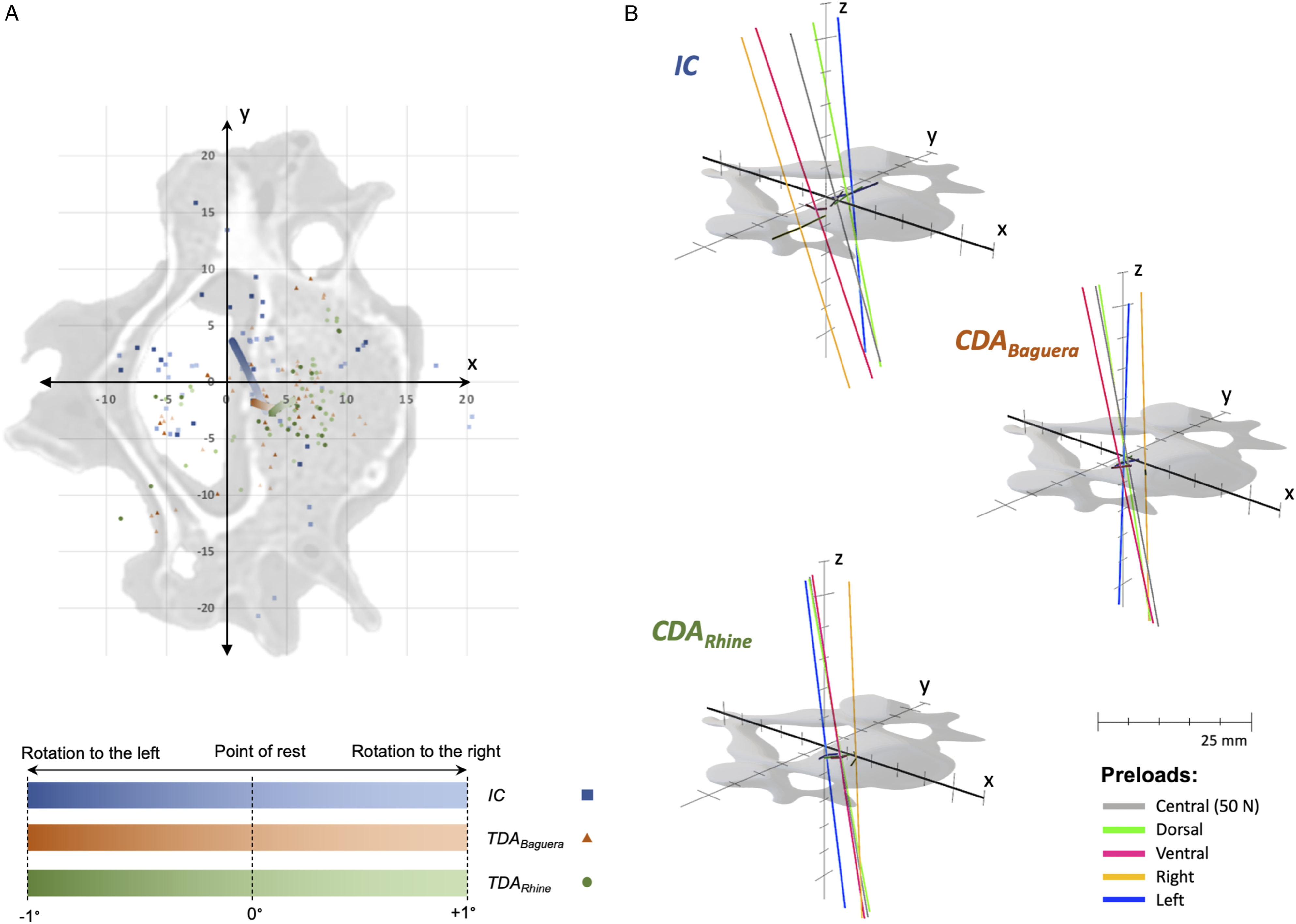
IHA Orientations
Both CDAs resulted in reduced reclination of the sagittal IHA orientation. This was significant for the 10 N central preload between the IC and the CDARhine, for the 50 N central preload and the dorsal preload between the IC and both CDAs, for the ventral preload between the IC and the CDARhine, and for the right preload between the IC and the CDABaguera (Table 1e) (Figure 4B).
The average lateral IHA orientation was nearly in the sagittal plane for all conditions. Lateral preloads led to a distinct inclination toward the corresponding site in the IC, but this phenomenon was not observed after the CDAs. However, the differences were not significant. A dorsal preload led to an inclination to the left of the lateral IHA orientation in the IC. This effect was smaller after the CDABaguera and nearly canceled after the CDARhine. In the latter, the difference between the IC and the CDARhine was significant (Table 1f) (Figure 4B).
Lateral Bending
IHA Migration
IHA Parameters During Lateral Bending.
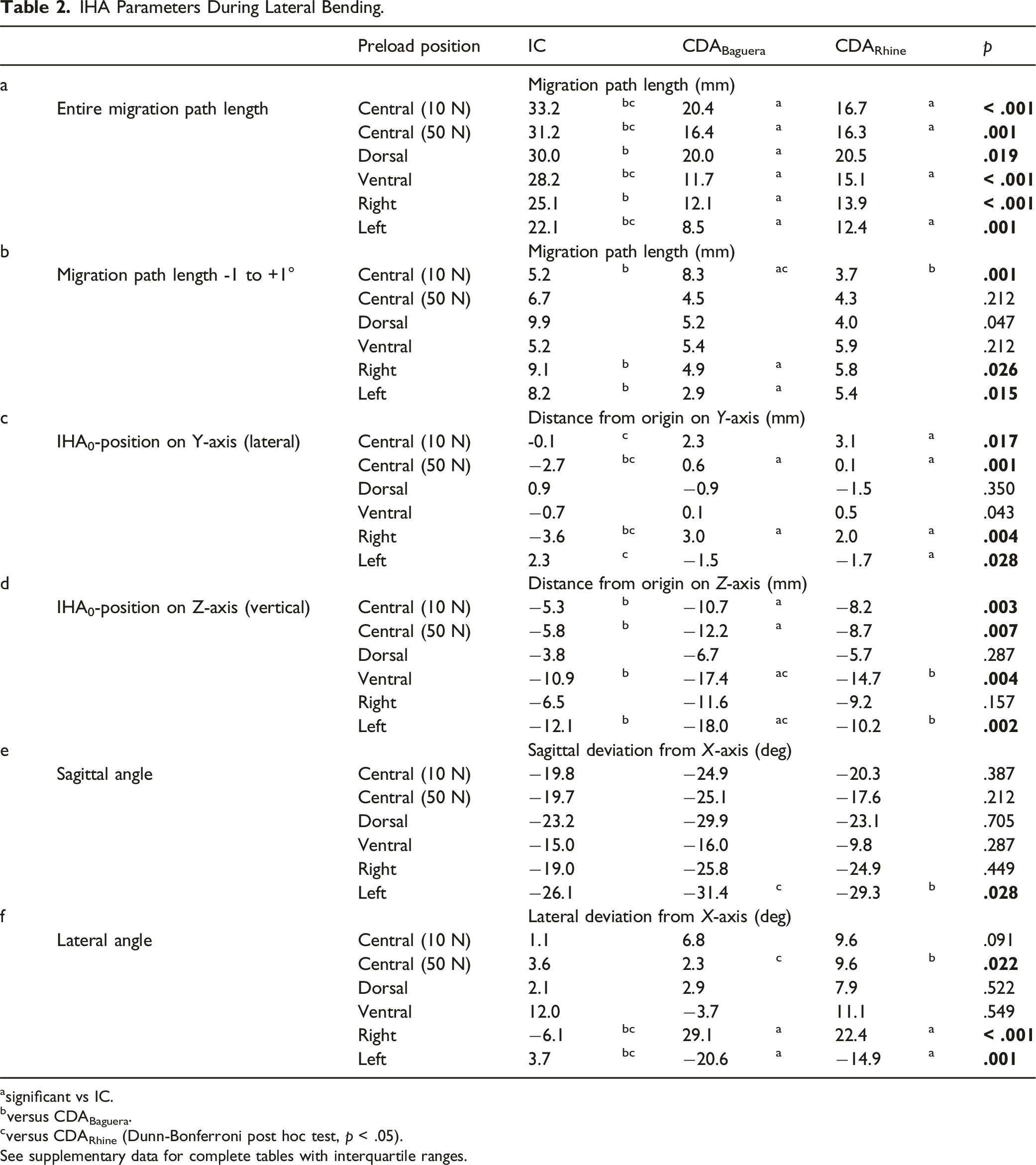
asignificant vs IC.
bversus CDABaguera.
cversus CDARhine (Dunn-Bonferroni post hoc test, p < .05).
See supplementary data for complete tables with interquartile ranges.
Referring to the range of γ ± 1.0°, the path length in the IC was significantly shorter than after the CDABaguera, and significantly longer than after the CDARhine under a 10 N central preload. Under both lateral preloads, the path length after the CDABaguera was significantly shorter than that in the IC (Table 2b).
IHA0-Positions
The IHA0-positions were located centrally in the cranial part of the lower vertebral body. Under a 10 N central preload, the lateral shift was significantly more leftward after the CDARhine than in the IC, while under a 50 N central preload in the IC, the IHA0-position shifted significantly to the right compared to both CDAs. In the IC, a right preload resulted in a rightward shift of the IHA0-position, and a left preload in a leftward shift of the IHA0-position. After both CDAs, a right preload led to a significant leftward shift of the IHA0-position compared to the IC, while a left preload led to a rightward shift (significant between the CDARhine and the IC) (Table 2c) (Figure 5A). IHA0-positions and orientation for lateral bending: (A) The IHA0-positions and the IHA migration paths for all the FSUs are depicted during lateral bending. The coordinates of the IHA0-positions (coronal plane) are plotted for rotation to the left (-1°), point of rest (0°), and rotation to the right (+1°). The rotation is represented by color strength (rotation to the left [-1°] with light color strength, point of rest [0°] with medium color strength, and rotation to the right [+1°] with full color strength). The IC are represented with a square (■), the CDABaguera with a triangle (▲), and the CDARhine with a dot (●). The IHA coordinates at - 1°, 0°, and +1° were quadratically polynomially regressed and are presented in bold lines. The average IHA migration paths for -1° to +1° lateral bending are depicted in black in the coronal plane. (B) The IHA orientations of the IC, the CDABaguera, and the CDARhine are depicted for lateral bending. The different preloads are represented in color. (C) The IHA orientations of the IC, the CDABaguera, and the CDARhine are depicted for lateral bending in sagittal (I) and coronal (II) X-ray of one specimen. In particular, the different IHA orientation in the IC and after both CDAs under lateral preloads become clear.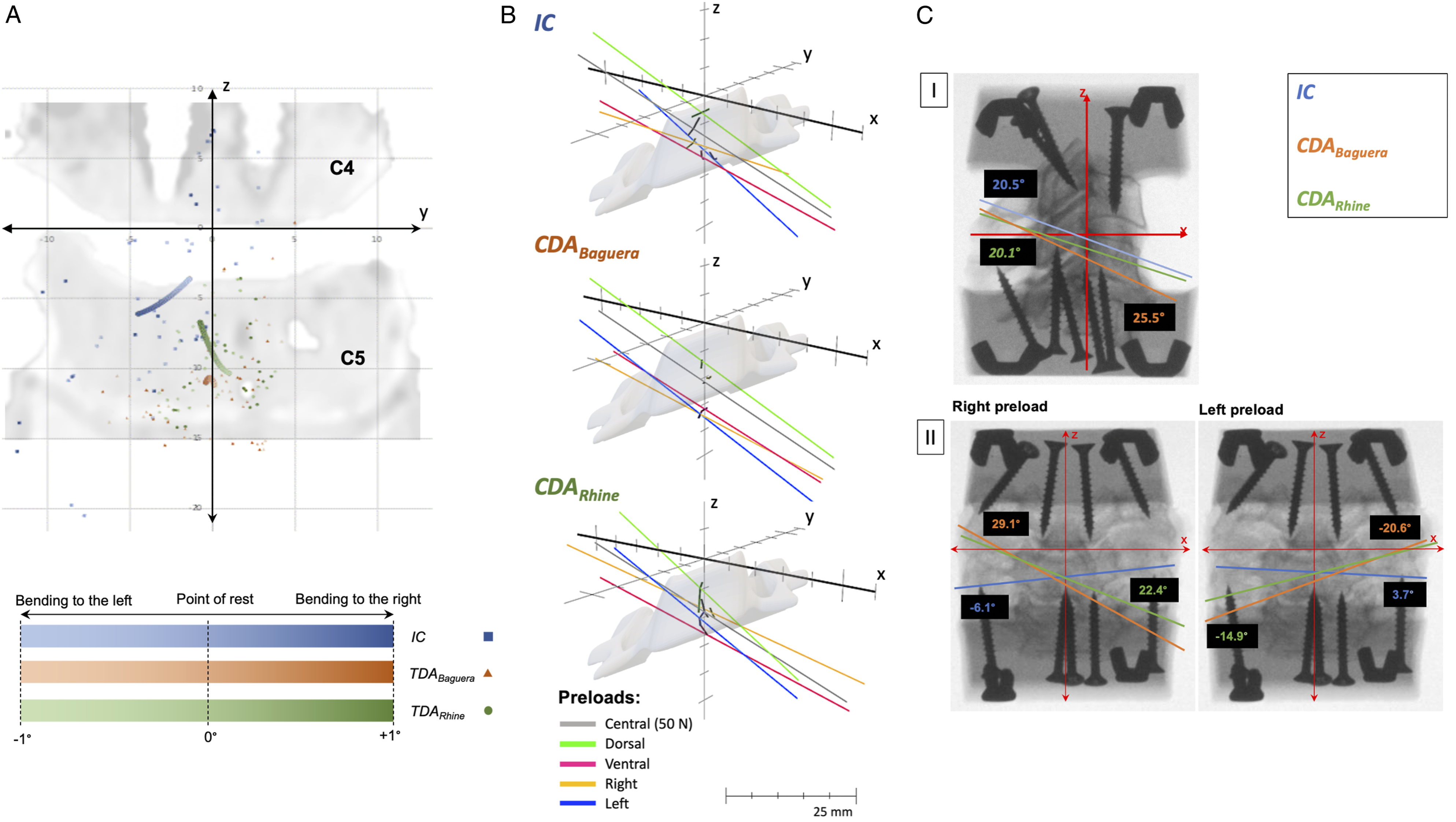
Regarding the vertical shift, under both central preloads, the IHA0-positions were significantly less cranial after the CDABaguera than in the IC. Under a ventral and a left preload, the IHA0-positions after the CDABaguera were significantly less cranial than in the IC and after the CDARhine (Table 2d) (Figure 5A).
IHA Orientations
The sagittal IHA orientation was reclined for all conditions. It was reclined significantly greater after the CDARhine than after the CDABaguera under the left preload (Table 2e) (Figure 5B, cI).
The average lateral IHA orientation was minimally rotated to the left for all conditions. Under a 50 N central preload and after the CDARhine, rotation to the left was significantly stronger than after the CDABaguera. In the IC, a right preload resulted in a rotation of the lateral IHA orientation to the right, and vice versa, while after both CDAs, a lateral preload resulted in a rotation to the non-corresponding site (significant between both CDAs and the IC) (Table 2f) (Figure 5B, cII).
Flexion/Extension
IHA Migration
IHA Parameters During Flexion/Extension.
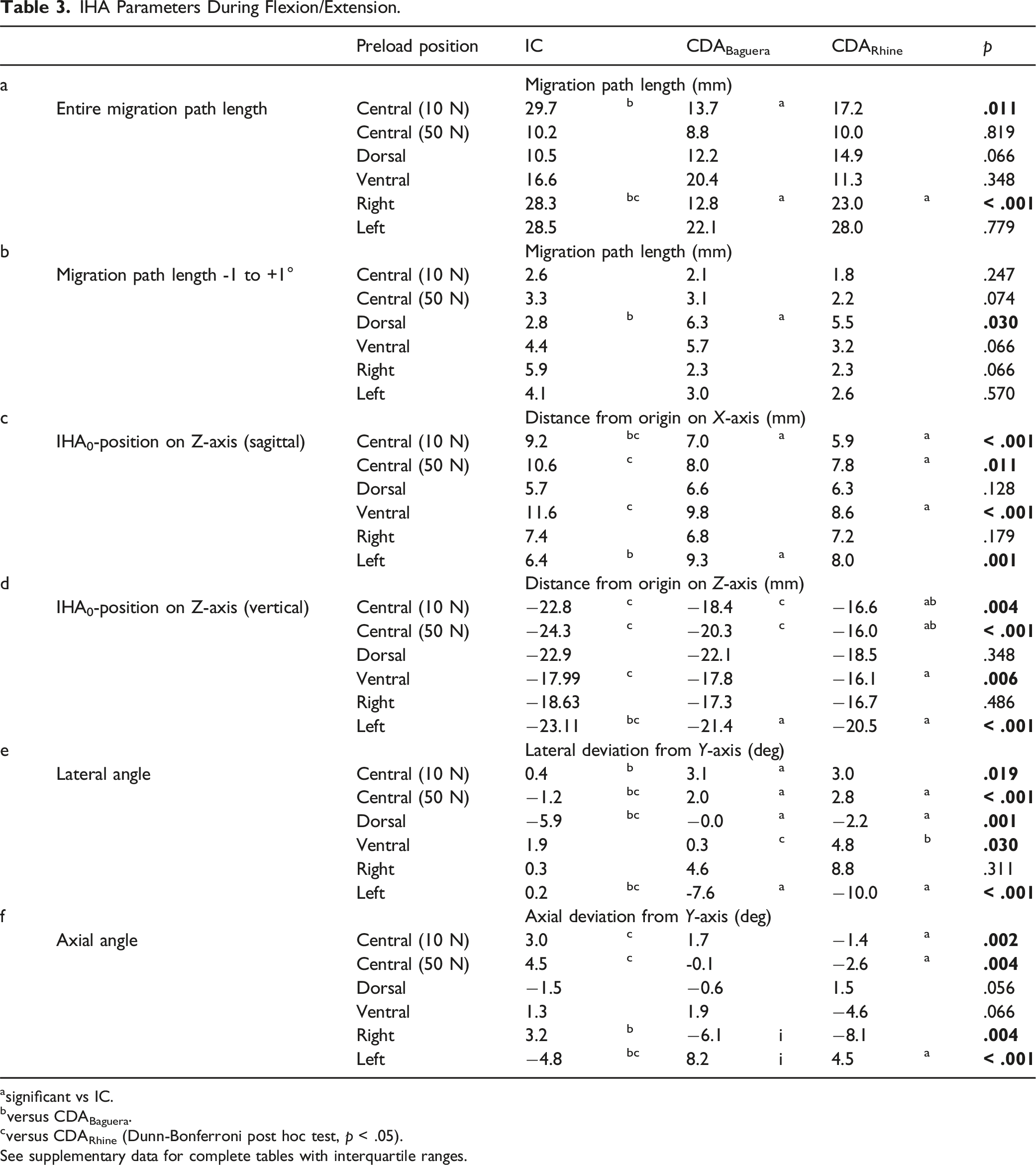
asignificant vs IC.
bversus CDABaguera.
cversus CDARhine (Dunn-Bonferroni post hoc test, p < .05).
See supplementary data for complete tables with interquartile ranges.
With a range of γ ± 1.0°, the path length in the IC was significantly shorter than after the CDABaguera under a dorsal preload (Table 3b).
IHA0-Positions
The IHA0-positions were located centrally in the caudal part of the lower vertebral body. Regarding the sagittal shift, the IHA0-positions were farther from the origin in the sagittal plane in the IC than after both CDAs. This was significant under a 10 N central preload for both CDAs and under a 50 N central and ventral preload for the CDARhine. Except under a left preload, the IHA0-position was significantly closer to the origin in the IC than after the CDABaguera (Table 3c) (Figure 6A). The IHA0-positions and orientations for flexion/extension: (A) The IHA0-positions and IHA migration paths for all FSUs are depicted during flexion/extension. The coordinates of the IHA0-positions (sagittal plane) are plotted for extension (-1°), point of rest (0°), and flexion (+1°). Flexion/extension is represented by color strength (extension [-1°] with light color strength, point of rest [0°] with medium color strength, and flexion [+1°] with full color strength). The IC are represented with a square (■), the CDABaguera with a triangle (▲), and the CDARhine with a dot (●). The IHA coordinates at -1°, 0°, and +1° were quadratically polynomially regressed and are presented in bold lines. The average IHA migration paths for -1° to +1° flexion/extension are depicted in black in the sagittal plane. (B) and (C): the IHA orientations of the IC, the CDABaguera, and the CDARhine are depicted for lateral bending. The different preloads are represented in color. In particular, the different IHA orientations in the IC and after both CDAs under lateral preloads become clear.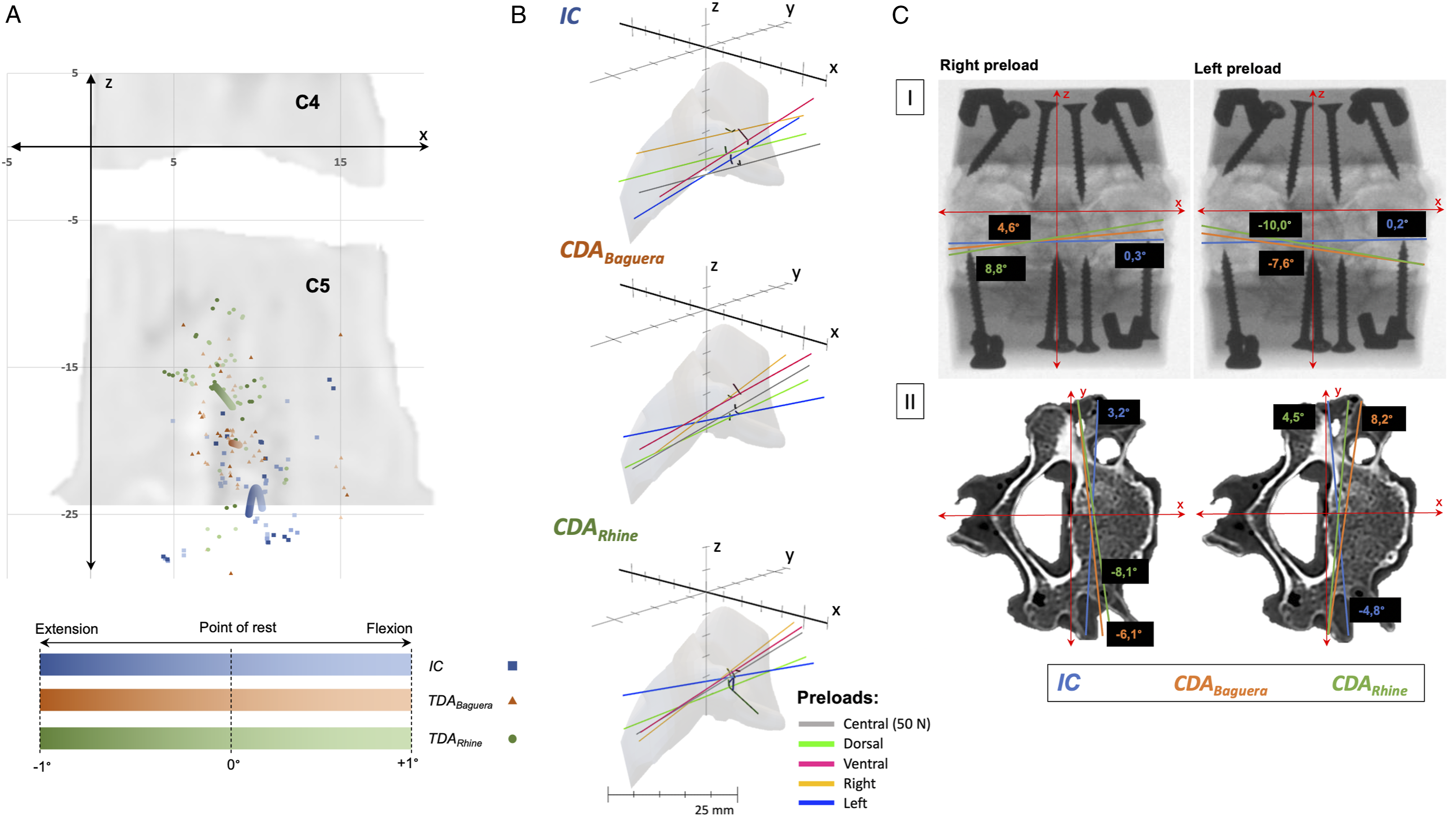
Regarding the vertical shift, under both central preloads, the IHA0-positions were significantly more cranial after the CDARhine than in the IC, as well as after the CDABaguera. Under a ventral preload, the IHA0-positions were significantly lower in the IC than after the CDARhine, and under a left preload, they were significantly lower in the IC than after both CDAs (Table 3d) (Figure 6A).
IHA Orientations
The average lateral IHA orientation was nearly in the axial plane for all conditions. Under a 10 N central preload, the IHA was significantly more inclined rightward after the CDABaguera than in the IC; under a 50 N central preload, both CDAs led to a significantly more rightward inclined IHA orientation than in the IC. Under a dorsal preload, the IHA was inclined leftward in the IC, while after both CDAs, the IHA was significantly less inclined. A ventral preload resulted in a significantly more rightward inclined IHA orientation after the CDARhine than after the CDABaguera. While lateral preloads hardly showed any impact on the IHA orientation in the IC, after both CDAs, the lateral IHA orientation was inclined toward the preloads’ corresponding sites. This was significant between both CDAs and the IC under the left preload (Table 3e) (Figure 6B, cI).
Under both central preloads, the axial IHA orientation rotated significantly more leftward after the CDARhine than in the IC. In the IC, lateral preloads resulted in rotation to the preloads’ corresponding sites, while this was vice versa after both CDAs. Under a right preload, this was significant between the CDABaguera and the IC, and under a left preload, it was significant between both the CDAs and the IC (Table 3f) (Figure 6B, cII).
Discussion
This study confirmed the existing reference data for the IHA in the IC.19,26 Furthermore, it offers a comprehensive analysis of the IHA after CDAs, considering all 3 motion dimensions. Although various singular IHA characteristics differed slightly between the IC and CDAs, the fullness of motion analyses could reveal a structural problem after CDAs. Hence, both CDAs showed a clear weakness in performing physiological IHA patterns under lateral preloads. Consequently, this implies that CDAs can preserve physiological motion characteristics to a certain extent when the head is upright or the neck is flexed or extended but fail when the head is tilted sidewards.
Anderst et al (2015) 26 assessed the IHA for C1 to T1 in vivo in 29 healthy participants via biplane radiographs. Jonas et al (2018) 19 observed the finite helical axes (which is different to the IHA since it is not measured instantaneously and continuously) in vitro in 6 humans for C2 to C7. Neither study applied preloads for extensive strains in its protocols. The focus of these experiments was on the FSUs’ ROM and on what we termed the IHA orientation. In general, the results of both studies were in line with our findings. Anderst et al (2015) 26 reported that for the IC in the FSU C4-5, the sagittal IHA orientations were approximately 44° under axial rotation, 35° under lateral bending, and 10° under flexion/extension. In their research, Jonas et al (2018) 19 observed approximately 70°, 30°, and 5° for axial rotation, lateral bending, and flexion/extension, respectively (data were approximated from graphs and illustrations in publications). Our results were slightly closer to the latter, with about 70° (adapted values since the transversal plane is used as a reference), 30°, and 5° for axial rotation, lateral bending, and flexion/extension, respectively. The large difference between Jonas et al (2018) 19 and Anderst et al (2015) 26 regarding the sagittal IHA orientation under axial rotation is supposedly the consequence of differences between in vivo and in vitro conditions. 17 Following this argument, our results showed more similarity to the in vitro conditions of Jonas et al (2018) 19 ; particularly regarding the sagittal IHA orientation under axial rotation.
Furthermore, the sagittal IHA orientations after the CDAs also resembled the IHA orientations in the IC in the broadest sense. However, under axial rotation, the sagittal IHA orientations were steeper after the CDAs than in the IC. Previous studies on IHA in the cervical spine showed no differences in sagittal IHA orientations.12,27 A reason could be the use of different types of prostheses than in the present study. Notwithstanding the statistical significance and indicating different motion patterns after the CDAs, these differences did not show fundamentally altered kinematics after the CDAs. This was the opposite when focusing on the IHA orientations under lateral preloads. In all 3 motion dimensions, the CDAs led to IHA orientations contrary to those in the IC and entirely changed the orientation (left to right and vice versa). To our knowledge, no study has encountered this issue using IHA analyses. Patwardhan and Havey (2020) 9 reported a potential mismatch of motion kinematics after CDA that could lead to an uncinate impingement and abnormal facet joints’ contact during lateral bending, which could explain our observation. In line with this hypothesis, the findings were contrary, or at least highly different IHA0-positions after both CDAs compared to the IC under lateral preloads during axial rotation and lateral bending. A reason for this might be the prostheses’ designs and the mobility of the core or the translational components of the ball-and-socket complex.9,28 Interestingly, both CDAs showed the same behavior contrary to the IC; hence, the results did not permit a preference for one particular prosthesis. Overall, these results suggest a weakness of both CDAs in dealing with lateral forces, although we do not suspect noticeably altered patient mobility in the process. However, the altered kinematics could possibly increase the risk for ASD. 16 Notwithstanding the compelling clinical data for CDAs compared with ACDF in terms of lower risk for ASD,1–3 optimization of prostheses could potentially reduce the risk of residual problems (e.g., ASD).
Regarding the IHA0-positions, Jonas et al (2018) 19 reported varying sagittal IHA0-positions on the Z-axis in the posterior part of the subjacent vertebral body during flexion/extension. We found the IHA0-positions located in the IC in the central part of the subjacent body close to the lower endplate. After the CDA, they migrated cranially, as reported previously.10,11 Conversely, during lateral bending, the IHA0-positions in the IC were at the height of the intervertebral disc or the upper endplate of the subjacent vertebra, while after the CDAs, the IHA0-positions migrated caudally. This is similar to earlier experiments, 21 however, this was more distinctive, and overall, the IHA0-positions were more caudal. The reasons for the differences could be the use of other prostheses and the intended dispense of a stabilizing solution.29,30
The length of the IHA migration paths decreased after the CDAs compared to the IC, except for one condition after the CDABaguera during flexion/extension. A previous finding also observed a shorter IHA migration path after the use of a ball-and-socket joint resembling Prestige LP Cervical Disc (Medtronic plc), while the soft lentoid elastic nucleus containing Bryan Cervical Disc (Medtronic plc) distinctly increased the length of the IHA migration path.10,12,21 The present findings imply that both prostheses maintained the length of the IHA migration path.
In summary, compared with our previous studies examining IHA after CDA in C3/4 and C5/6, we showed similar levels of IHA0-positions on the one hand, as mentioned, and different behavior of IHA migration pathways on the other.10,21 Regarding the IHA orientation under lateral bending, a ventral inclination of approximately -20° was observed in IC in the current study. In the previous studies, C3/4 had a ventral inclination of approximately -25° and C5/6 had a ventral inclination of approximately -13° in IC.10,21 Thus, the current value for IC is between the previous values. The increase in ventral inclination in the upper cervical spine is consistent with other studies. 26 After CDA, ventral inclination under lateral bending increased in both new and previous studies.10,21 Regarding the IHA orientation under flexion/extension, previous studies largely showed parallelism with the applied coronal torque. 10 This was also evident in the current study for both IC and after both CDA.
Both previous studies showed no differences in IHA parameters when comparing the different preloads.10,21 The characteristic patterns of structural kinematic changes after CDA under lateral eccentric preloads could only be observed in the current study. Possible reasons are the use of different CDAs and the use of fresh-frozen specimens compared to previous studies. The formalin used in the previous studies influences the biomechanical properties and in particular leads to a reduced range of motion. 30
Two major differences were found between the 2 CDAs in the current study: Under lateral bending and flexion/extension, the IHA0-positions were more caudal after the CDABaguera than after the CDARhine. An explanation could be the different prosthetic designs. The CDABaguera reflects the typical design of a ball-and-socket prosthesis; the CDARhine is a non-articulating monoblock prosthesis with an elastomer-polyurethane core. It is possible that the biomechanical center of rotation of the CDABaguera is lower than that of the CDARhine in relation to its height.
This study has the following limitations: (1) Being an in vitro study, the results should be interpreted with caution; notably, the findings for the IC resemble in vivo results. 26 (2) The degradation of FSUs during experiments is possible, although they are performed as quickly as possible. (3) The studies were performed on specimens from body donors of advanced age. Although CT scans were used to ensure that the FSU C4/5 was intact and showed no degeneration above grade I according to Kellgren and Lawrence, 20 a limited transferability of the results to younger age groups must be considered. (4) Muscular and soft tissue was removed because standardized preservation of these tissues is difficult. Muscular tissue might have changed the results. (5) According to Cescon et al (2014) 31 ; input noise can cause inaccurate calculations of the position and orientation of the IHA, especially when examining very small IHA intervals. The present study relies on differences in IHA between these small intervals, and therefore may be susceptible to the effects of input noise. Consequently, caution should be exercised when interpreting the precise values of the IHA orientation and position in this study. However, the measurements of the differences between intact conditions and those after CDA are reliable, as they were calculated in the same manner under all conditions. (6) Bound eccentric forces were applied, which might lead to non-uniform load distribution along the specimen, resulting in limited comparability with in vivo conditions or pure moment loading. (7) The analyses for the IHA orientation and IHA0-positions include only data for the neutral zone (γ = 0°). This might have neglected the elastic behavior of the ligaments and the effects of joint surface contacts, resulting in limited applicability for clinical conditions. (8) The data was not normalized for the different prostheses’ sizes.
Supplemental Material
Supplemental Material - Cervical Disc Arthroplasties Fail to Maintain Physiological Kinematics Under Lateral Eccentric Loads
Supplemental Material for Cervical Disc Arthroplasties Fail to Maintain Physiological Kinematics Under Lateral Eccentric Loads by Paul Jonathan Roch, Constantin Hemprich, Friederike Klockner, Marc-Pascal Meier, Katharina Jäckle, Wolfgang Lehmann, Martin Michael Wachowski and Lukas Weiser in Global Spine Journal
Footnotes
Acknowledgments
We would like to thank Prof. Dr. A. Schilling for the support and the use of the laboratory.
Authors’ Contributions
All authors were fully involved in the study. Each author focused on a particular issue: Study conception and design: PJR, WL, MMW, LW Acquisition of data: CH, FSK, MPM, KJ Statistical analysis: PJR, CH, MPM, LW Analysis and interpretation of data: PJR, CH, FSK, MMW Drafting of manuscript: PJR Critical revision: WL, MMW, LW All authors read and approved the final version of this manuscript.
Declaration of conflicting interests
The author(s) declared no potential conflicts of interest with respect to the research, authorship, and/or publication of this article.
Funding
The author(s) received no financial support for the research, authorship, and/or publication of this article.
Disclosure
All authors disclose any financial and personal relationships with other people or organizations that could inappropriately influence (bias) their work (e. g. employment, consultancies, stock ownership, honoraria, paid expert testimony, patent applications/registrations, and grants or other funding).
Exclusive Submission
The authors hereby declare that the manuscript, including related data, figures and tables has not been previously published and the manuscript is not under consideration elsewhere.
Supplemental Material
Supplemental material for this article is available online.
Appendix
References
Supplementary Material
Please find the following supplemental material available below.
For Open Access articles published under a Creative Commons License, all supplemental material carries the same license as the article it is associated with.
For non-Open Access articles published, all supplemental material carries a non-exclusive license, and permission requests for re-use of supplemental material or any part of supplemental material shall be sent directly to the copyright owner as specified in the copyright notice associated with the article.