
Abstract
Study Design
Biomechanical study.
Objectives
Several strategies to improve the surface of contact between an interbody device and the endplate have been employed to attenuate the risk of cage subsidence. 3D-printed patient-specific cages have been presented as a promising alternative to help mitigate that risk, but there is a lack of biomechanical evidence supporting their use. We aim to evaluate the biomechanical performance of 3D printed patient-specific lumbar interbody fusion cages in relation to commercial cages in preventing subsidence.
Methods
A cadaveric model is used to investigate the possible advantage of 3D printed patient-specific cages matching the endplate contour using CT-scan imaging in preventing subsidence in relation to commercially available cages (Medtronic Fuse and Capstone). Peak failure force and stiffness were analyzed outcomes for both comparison groups.
Results
PS cages resulted in significantly higher construct stiffness when compared to both commercial cages tested (>59%). PS cage peak failure force was 64% higher when compared to Fuse cage (P < .001) and 18% higher when compared to Capstone cage (P = .086).
Conclusions
Patient-specific cages required higher compression forces to produce failure and increased the cage-endplate construct' stiffness, decreasing subsidence risk.
Introduction
Lumbar interbody fusion (LIF) surgery is performed to treat different spine pathologies, and the indication for its use has been refined with the emergence of better evidence. 1 With varying types of interbody fusion devices (IFD), LIF has improved fusion rates, helped correct deformities, improve coronal and sagittal balance, and establish mechanical stability.2,3 The added advantage of LIF surgery is that it also restores the disc space height, thus directly and indirectly decompressing neural elements. 4
However, implant subsidence remains a significant concern after LIF, and the reported occurrence rates range from 7% to 38%. 5 After subsidence, the clinical outcomes can worsen, resulting in increased pain and loss of alignment, stability, and the indirect decompression of the neural elements. 6 Smaller IFD sizes used in posterior surgery have been correlated to an increased risk of implant subsidence. 7 Also, different materials have been used for cage manufacturing. Titanium and polyetheretherketone (PEEK) remain the most commonly utilized materials. Titanium has several advantages, including improved osteoconductive potential, but with an elastic modulus of 110 GPa seems more prone to subsidence. PEEK has a smaller elastic modulus of around 4 GPa, is less prone to subsidence than titanium and closer to the bone elastic modulus (2.5 GPa). However, its surface is not osteoconductive, and bone integration is compromised.4,8
Improvements in medical imaging and 3D image acquisition and processing have allowed for strategies to reduce subsidence risk via the use of patient-matched implants. 9 Finite element cage models have shown a decrease in stress distribution across the cage and the endplate by matching the endplate shape.8,10,11 Finite element models contain idealized shapes and are expected to perfectly match the 3D endplate cross-section area, which is unlikely to be reproduced in the clinical situation.
Rapid prototyping, or three-dimensional printing(3DP), is a manufacturing process with increasing applications in spine surgery.9,12 3DP has been described in several case reports using patient-specific (PS) cages for LIF surgery in patients with complex anatomy where a generic implant would not be suitable. 13 Although PS cages have already been described in a clinical scenario, 9 there remains much to investigate, including the influence of residual mismatch between the final implant surface and the patient's endplate, related to image acquisition modalities, 14 and the limitations in 3DP layers resolution. 15 Despite the intuitive advantages of 3D printed patient-specific LIF cages in limiting subsidence, the literature lacks evidence confirming their biomechanical superiority in relation to commercially available cages.
In the present biomechanical study, we use a cadaveric model to investigate the resistance to subsidence in small LIF patient-specific cages and compare their performance to commercially available cages.
Materials and Methods
Anatomical Specimens
After institutional Research Ethics Board (REB #115303) approval, 5 fresh-frozen lumbar spine cadaveric samples were subjected to CT-Scan to obtain an image for the segmentation process and screen for bone tumours or fractures. The soft tissues were left intact during the imaging process, and the scanning protocol followed typical settings for clinical imaging of the lumbar spine in our institution.
The vertebrae were isolated from L1 to L5 and prepared in a similar way, as described in previous studies. 16 The muscles were resected, and the specimens were carefully cleaned to avoid damaging the bones inadvertently. A gentle sharp dissection using a scalpel and curette was used to remove soft tissue. During the cartilaginous endplate removal, special care was taken to avoid damage to the underlying bony endplate. After removing all the soft tissue, the bones dried at room temperature and were potted in cement with the cranial endplate parallel to the ground.
Bone Segmentation
An open-source software, 3D Slicer (version 4.10.2), was used to create 3D mesh models by importing the CT digital imaging and communication in medicine (DICOM) files.
A region of interest was created around each lumbar vertebral body (L1-L5), and each vertebra model was created using semi-automatic segmentation by the ‘grow from seeds’ extension in the Segment Editor of 3D Slicer (Figure 1). Bone and soft tissue were extracted based on different Hounsfield Units (HU), with care taken to compare the final segmentation model to the original CT-scan reconstruction, and the 3D bone model was exported as a stereolithography (STL) file. Also, an outer shell around the vertebrae was created using the 'Hollow' extension to allow the creation of an endplate guide later to help position the cage (Figures 4(A) and 5(A)). Example of individual vertebra segmentation of the lumbar spine using 3D Slicer.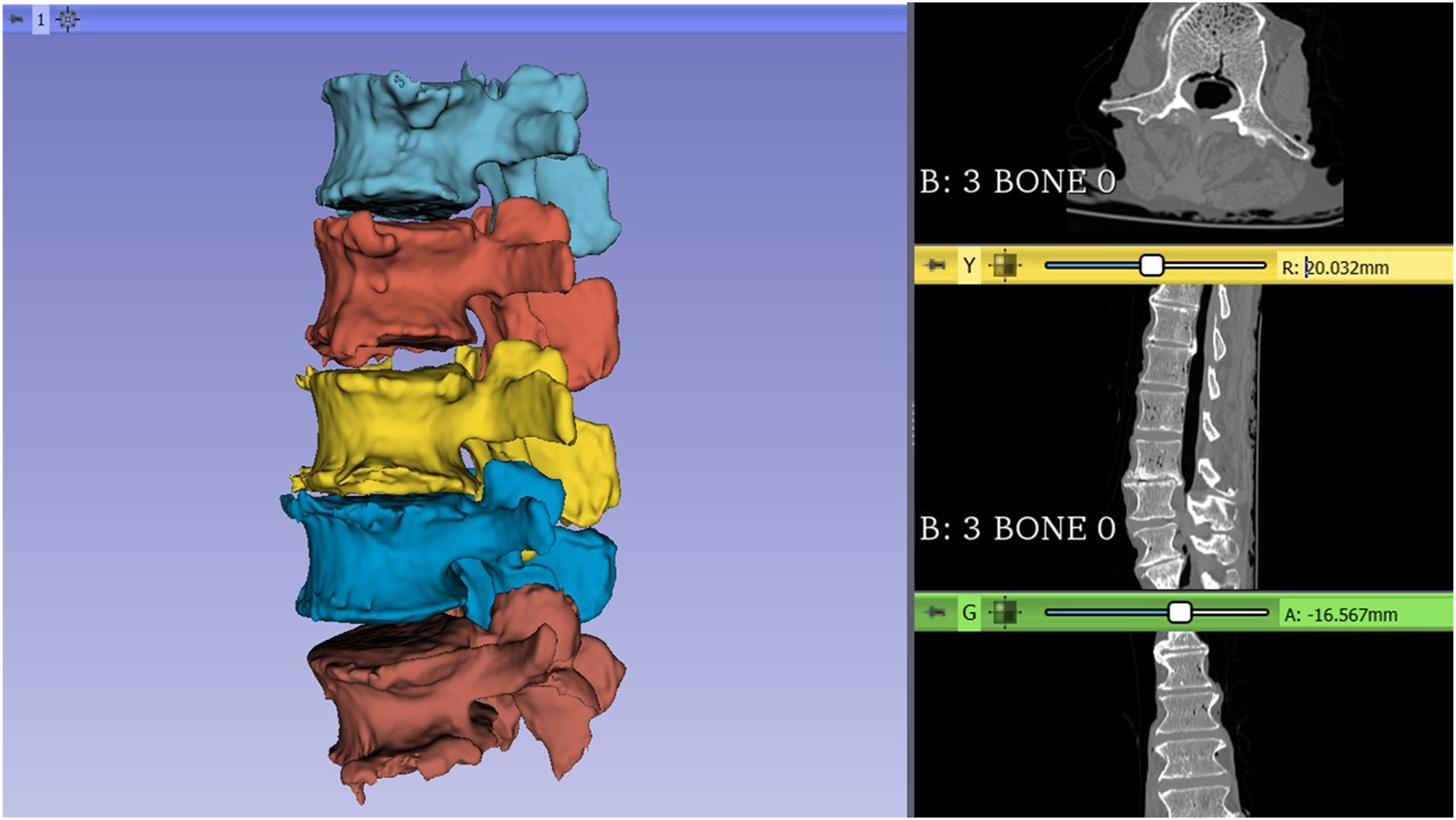
Interbody Fusion Devices
Two commercially available LIF cages, commonly used at our institution, were chosen for use in this study (Medtronic Sofamor Danek USA, Inc., Memphis, TN, USA). The first is made out of titanium alloy (FUSE™ Spinal System); the other is made out of PEEK (CAPSTONE® PEEK Spinal System) (Figure 2). Both implants had the same width (10mm) and length (22mm). Images showing pictures of the original Fuse and Capstone cages (A, B).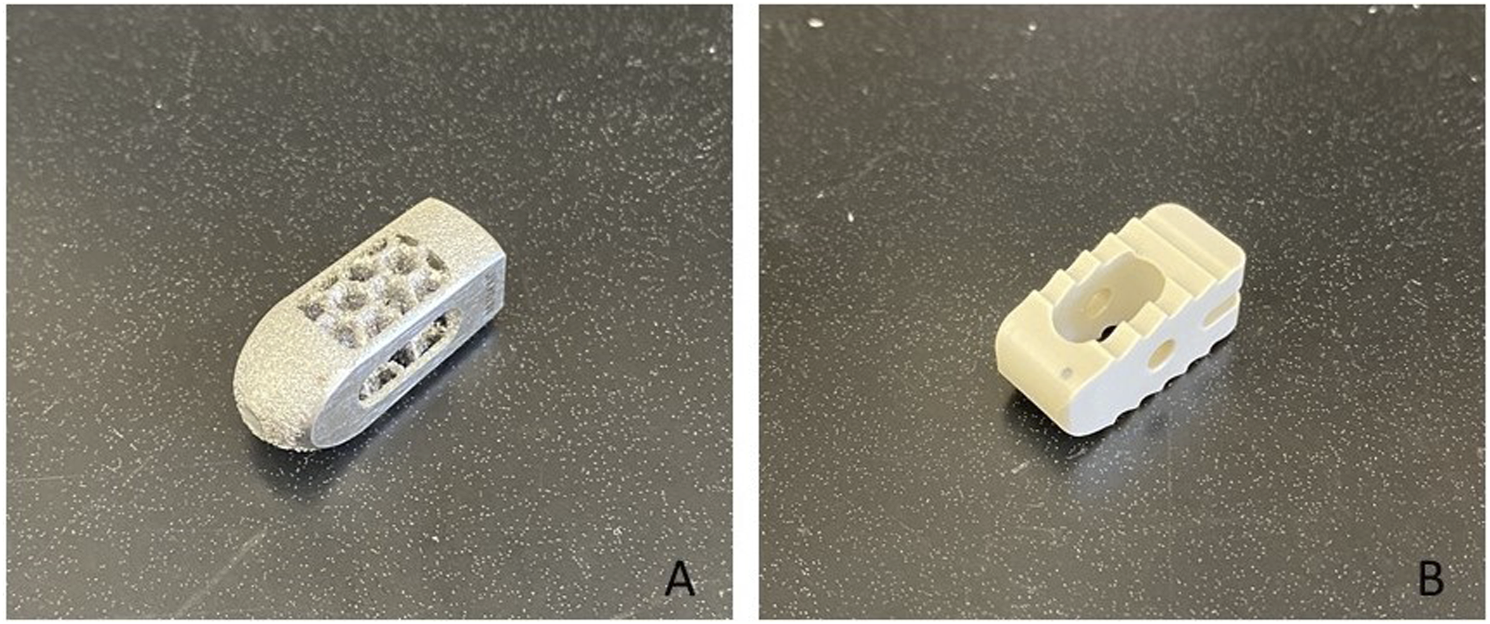
Through reverse engineering processes, the dimensions and features of the commercial cages were replicated digitally in CAD 3D modelling software (SolidWorks 2019, Dassault Systèmes Solidworks Corp). Reverse-engineering the commercial devices allowed all the cages to be 3D printed using the same material to avoid differences in material behaviour associated with biomechanical testing.
Patient-specific Cages
A new solid cage with the same commercial cages dimension was designed to be used during the Boolean subtraction procedure. The reverse-engineered cages and the newly designed cage were initially designed as a full implant and then cut in half and modified to add a base that enabled the implant to be attached to the testing machine (Figure 3). A custom clamp was created and printed to connect to the testing machine to prevent the cage from slipping out of position as the downward force was applied, ensuring the planned cage position stayed constant during testing (Figure 5). Images showing the newly designed implant CAD model (A) and the model used for the Boolean subtraction (B), also, the reverse-engineered Capstone cage(C) and the implant used during the biomechanical testing(D).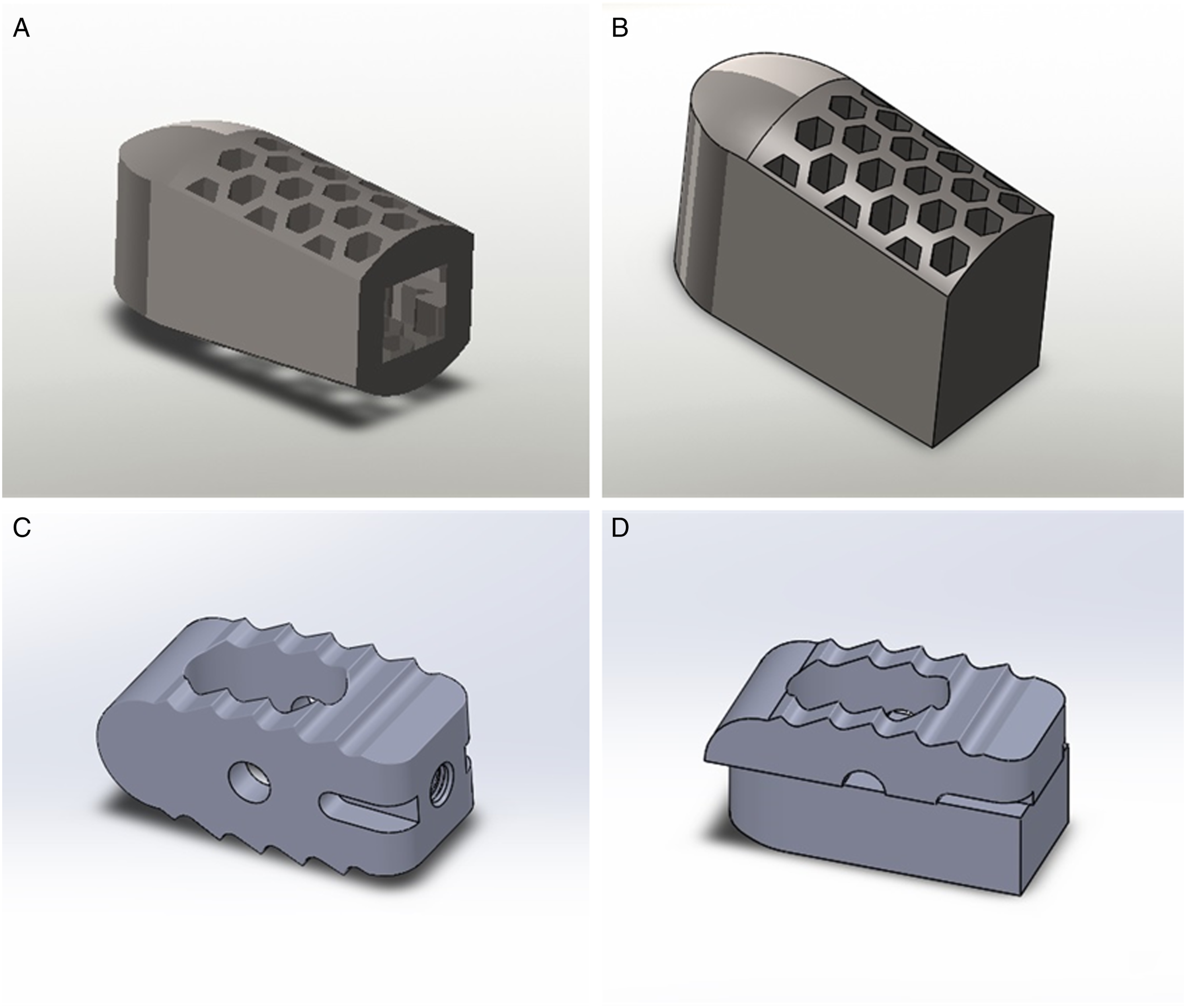
The superior endplate models and the solid cage model were imported into an STL editing software (Netfabb, Autodesk Inc, San Rafael, California). Two solid cage implants (left and right) were translated for every endplate until their geometry was overlapping with each vertebra's superior endplate in a similar position it would be placed during a LIF surgery procedure and corresponding to the position where it would be tested during the test-to-failure on the cadaveric bone. The fellowship-trained spine surgeons authors performed all the cage-position planning so that both cages would be equidistant from the endplate midline, in the same angulation, and restricted inside the vertebral body boundaries. After that, a Boolean subtraction operation was performed to create 2 patient-specific LIF cages per vertebra. Also, a positioning guide for each endplate was designed during the Boolean subtraction to place the cages in the pre-planned position during testing (Figure 4(A)). Every PS cage and endplate guide was exported as an STL file. The image shows the PS cages and guides to help place the custom cage in the correct position during the Boolean subtraction(A) and the final aspect of 1 of the PS cages(B).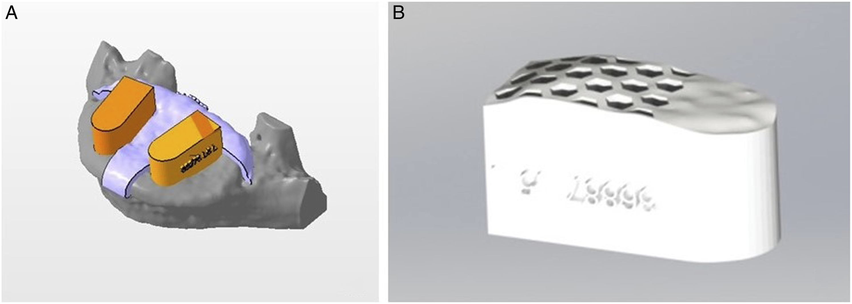
Cage 3D Printing
All the STL files, including the endplate guides, the reverse-engineered cages, and the patient-specific cages, were imported into the FormLabs PreForm software to be printed using Form 2 (FormLabs, Somerville, Massachusetts) printer. The layer thickness was set to 50 microns to improve resolution. The PS cages were printed in 'Rigid resin' (FormLabs, Somerville, Massachusetts), which is reinforced with glass fibre making it resistant to deformation and has an Elastic Modulus similar to PEEK.
Sample Size
Out of the 25 vertebrae, only 18 vertebrae were available for testing since 7 had previous fractures or were damaged during the harvesting and cleaning process. They were then balanced in 2 groups of 9 vertebrae each, and each group was assigned to an independent comparison group (patient-specific vs replicated Fuse and patient-specific vs replicated Capstone), allowing 9 samples per comparison group, more than the recommended for biomechanical testing experiments. Within each group, each vertebra's left and right sides were tested for the patient-specific cage on 1 side and the commercial cage on the contralateral side to control for potential differences in bone mineral density (BMD) among the cadavers.
Testing Set-Up
After determining each ideal cage position using the endplate guides (Figure 5), half of the vertebrae (n=9) received a PS cage on the left side while the other half on the right side alternately; therefore, 1 of the replicated commercial LIF cages was placed on the opposite side, and each specimen served as its own control. The cages were compressed axially over the vertebra's endplate at a rate of .1 mm/s
17
using an electromechanical testing machine (Instron® 5967, Norwood, MA, USA) until structural failure of the cage, vertebra, or both. Axial compressive force and displacement were recorded by the tester's dedicated software. Failure load (in Newtons, N) and construct stiffness (in N/mm) were extracted from the load-displacement curves. Failure load was defined as the maximum load achieved in the load-displacement graph before the failure occurs, whereas stiffness as the slope of the linear portion of the load-displacement curve before a failure occurs. (A) Ideal cage position was determined endplate guide and cage, (B) positioning was recorded with marking pen, (C) PS cage was used to determine testing position, and (D)commercial cage being placed in the same position for testing.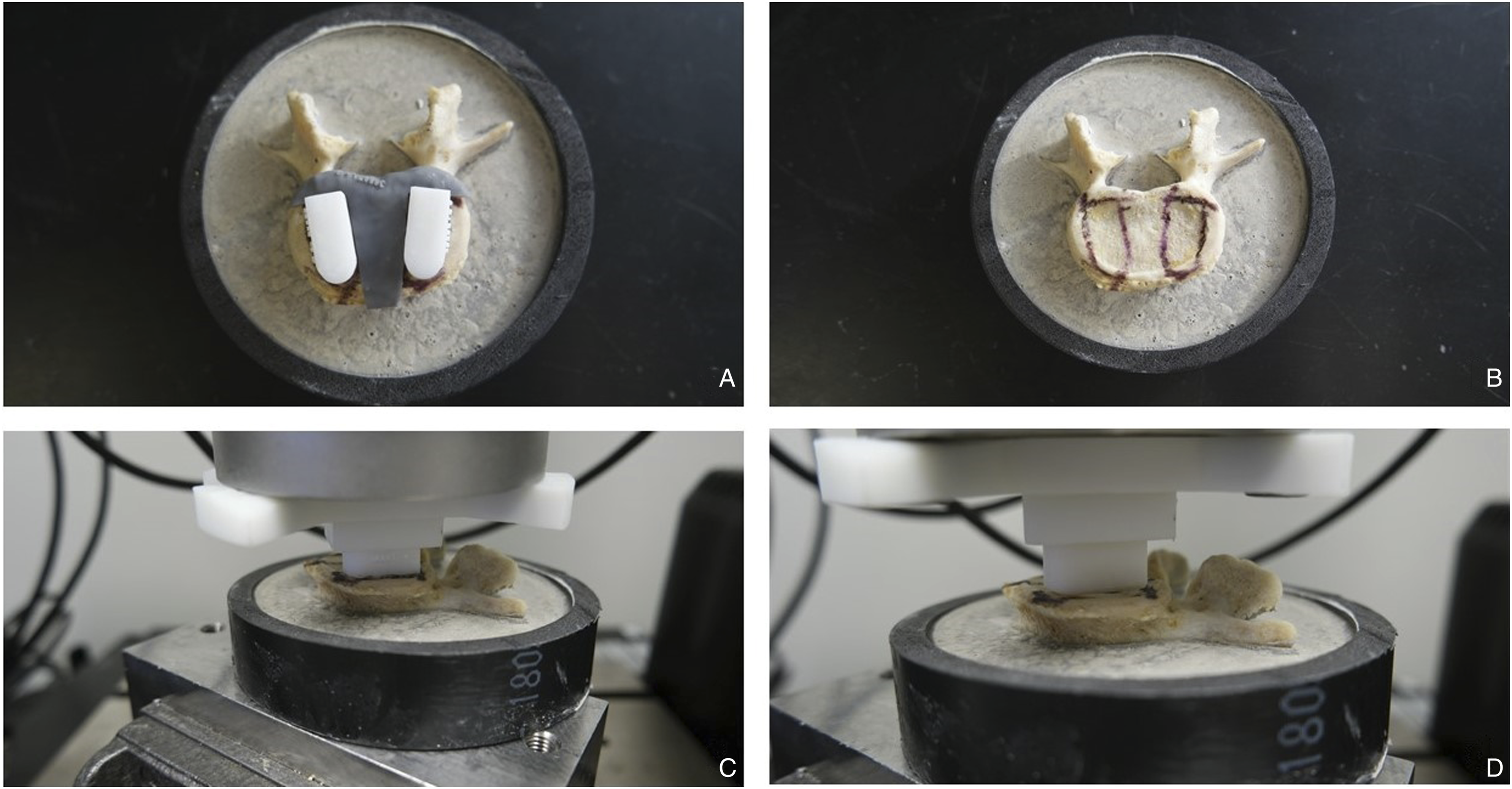
Statistical Analysis
All statistical analyses were conducted using IBM SPSS version 26 (IBM Corp., Armonk, New York, USA). Comparison between cages in each group was made using the Mann-Whitney U test. Statistical significance was set at P<.05.
Results
Failure Force
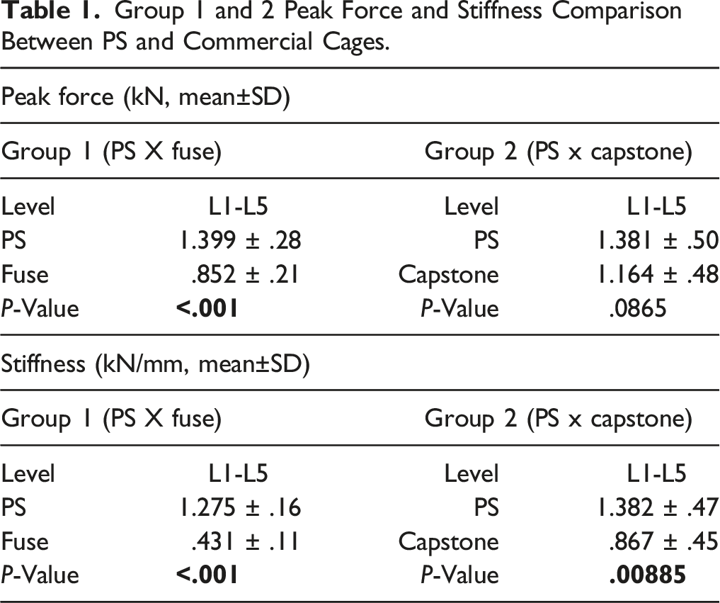
For the first group, where PS cages were compared to the Fuse cages, the failure force (mean±SD) was 1.399 ± .3 kN for the PS cage, and .852 ± .2, for the Fuse cage (P < .001)
Group 1 and 2 Peak Force and Stiffness Comparison Between PS and Commercial Cages.
Stiffness
For the first group, the stiffness (mean±SD) was 1.275 ± .2 kN/mm for the PS cage, and .431 ± .1 kN/mm, for the Fuse cage (P < .001).
For the second group, the stiffness (mean±SD) was 1.382 ± .5 kN/mm for the PS cage, and .867 ± .5 kN/mm, for the Capstone cage (P = .009) (Table 1).
Failure Mode
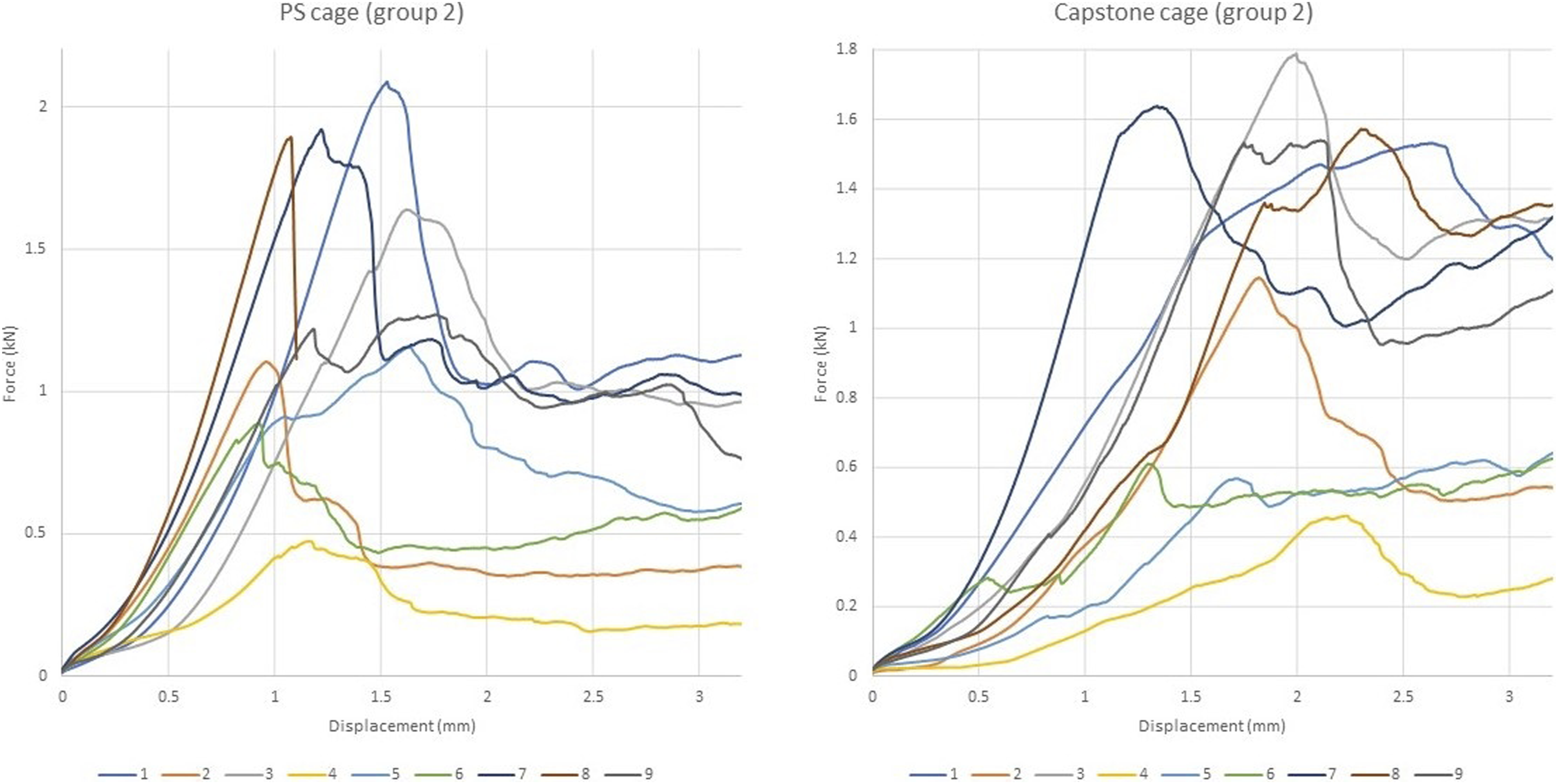
Among the cages tested, the most observed failure mode for the cages in both groups during testing was fracture of the cortical layer of the endplate followed by subsidence. None of the tested constructs failed due to vertebra fracture or implant failure (Figures 6 and 7). Force-displacement plots for PS and Fuse cage in group 1. Force-displacement plots for PS and Capstone cage in group 2.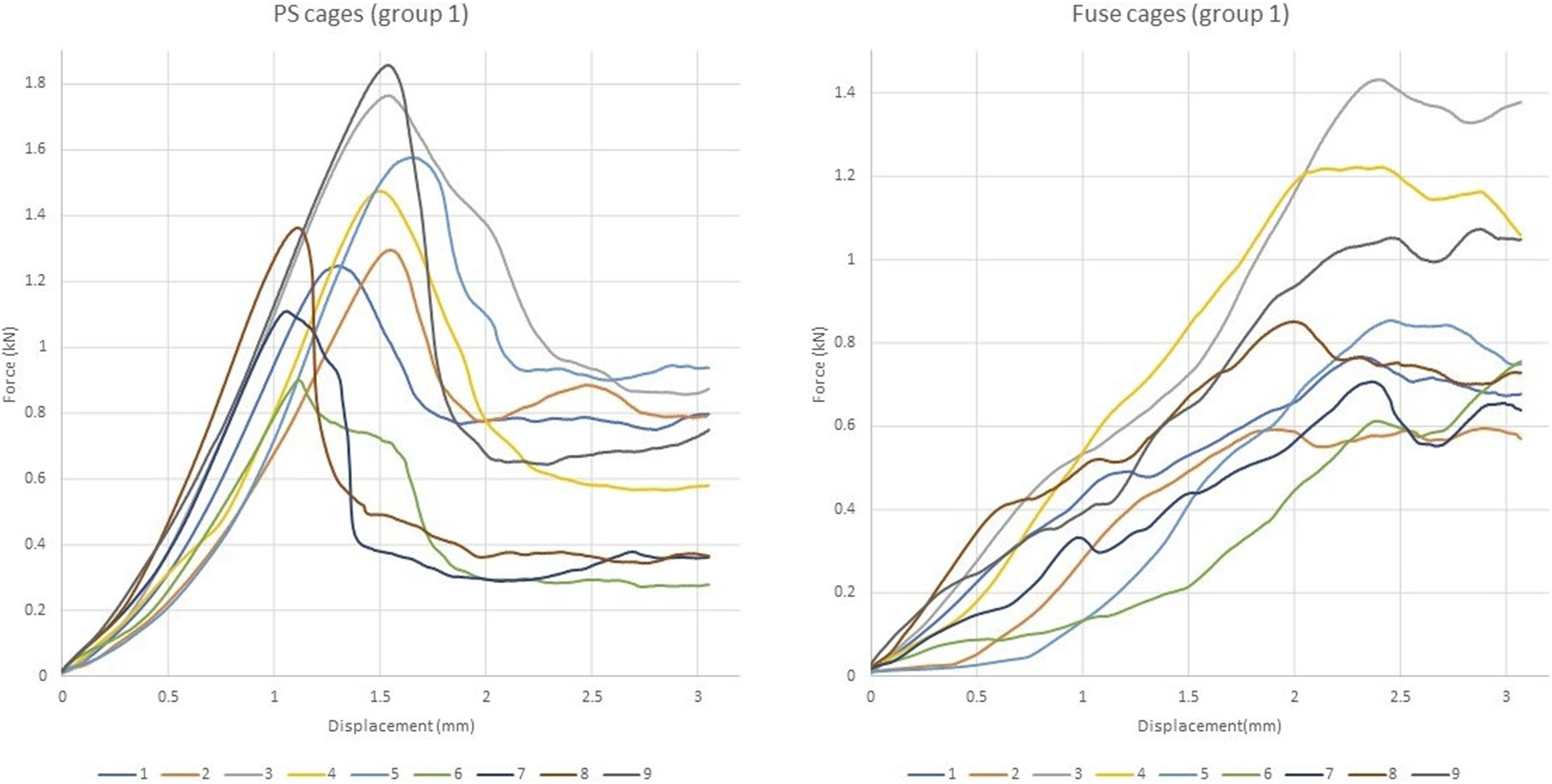
Discussion
This study's main findings showed that LIF patient-specific cage bone interface could be up to 1.6 times stiffer than the commercially available cages used for this study, and they required up to 64% more force to subside. The study compared IFDs developed to match the endplate contour to 2 types of cages widely used for LIF procedures and provides concrete biomechanical evidence of 3D printed devices' superiority.
Choi et al described subsidence as an expected incorporation process of the cages to the endplates that increases contact with the bone via the bone fracturing and conforming to the cage over time, rather than the cage conforming to the bone immediately as in our study. 18 Cage subsidence causes a reduction in the disc space and foraminal height, which can cause a recurrence of neurological symptoms and loss of the desired alignment. Therefore, better strategies to avoid subsidence and increase contact area are needed.
Yuan et al 7 showed that larger LLIF cages could reduce subsidence risk compared to smaller LIF cages due to the cages' increased surface area. However, cage size is limited through the posterior approaches due to the limited dissection corridor, 19 which is the vast majority of interbody fusion surgeries. 20 Alternatively, rather than increasing the cage size to maximize contact area, using a device that matches the endplate surface shape can increase the area of contact between the cage and the endplate, thereby reducing the risk of subsidence.
Previous studies using finite element analysis showed that patient-specific cages could reduce the stress distribution across the cage and endplate surface, thus reducing subsidence risk.8,10,11 The main drawback of finite element analysis is that the models perfectly match the 3D endplate cross-section area. It has been shown that there are size and volume differences between the CT scan-based 3D model and the human bone.14,21 The present study demonstrated that biomechanical superiority is maintained for the 3D printed models, even though a mismatch may remain between the cage surface area and the bone. 22 The customized shape of the PS cages seemed to play a significant role in the prevention of subsidence due to the better conformation of the implant inside the concavity of the endplate, generating better force distribution and reducing peak stress. After the Boolean operation, the final design of the PS cage found a good fit in the macroanatomy of the endplate. From our point of view, it can also be beneficial in preventing cage displacement inside the disc space or even posterior migration of the device. Zhou et al 23 found that endplate shape, posterior cage placement and endplate injury are risk factors for cage retropulsion. Patient-specific cages could better fit the endplate contour, helping to overcome these problems. The imaging modalities' limitations include a loss of accuracy in regard to the microanatomy of the endplate but still delivering better results than the commercial cages. 22
Another factor influencing subsidence risks is the mismatch between the endplate elastic modulus and the cages' material elastic modulus. 24 Due to the higher elastic modulus, titanium cages are more prone to subside than PEEK cages. 8 Titanium has an elastic modulus of 110 GPa, and PEEK has a smaller elastic modulus of around 4 GPa, which is closer to the bone elastic modulus (2.5 GPa). However, the PEEK surface is not osteoconductive, and bone integration is compromised compared to titanium.4,8 In a study by Fogel et al using titanium and PEEK devices with the same design shape, the cages had significantly different outcomes during in vitro tests 25 . For this study, we reverse-engineered all the commercial cages and printed them using the same 'Rigid' resin used for the PS cages, standardizing the material for cage comparison. Therefore, we believe that only the design shape played a major role in the subsidence of the cages. Although subsidence mechanisms are not fully understood, to avoid implant subsidence, the mismatch between the endplate properties and cage properties must be reduced to improve the strength of the vertebra-device interface. 24
The large elastic modulus mismatch between the materials used in orthopaedic surgery and the surrounding human bone is recognized as a cause of bone resorption, stress shielding and implant loosening. 26 In hip replacement surgery, several modifications in design, coating and biomaterials were made to the femoral component of the hip prostheses to reduce the bone resorption and allow better distribution of stresses. 26 In our study, we standardized the materials for cage testing to exclude the different materials variable from the equation. The differences in elastic modulus between PEEK and titanium are less important during testing to failure as there is not enough time for bone remodelling. A PEEK implant should see more deformation when compared to a titanium implant, and this could lead to a more even stress distribution if the PEEK implant is deforming and conforming to the endplate. However, the PEEK implant will not be under any significant deformation at the forces seen in the study. The primary contribution to displacement is the deformation of the bone caused by stress, calculated by force over area. A higher contact area will lead to lower stresses on the bone and, therefore, less displacement and higher stiffness. This is further supported by the PS cage data, which showed substantially higher stiffness due to increased contact area.
We do recognize that our benchtop in-vitro study has several limitations in translating this idea into real-life surgeries. We did not measure BMD, but the PS cages and the replicated commercial cages were paired so that they would serve as their own control to avoid bias due to potential BMD differences among the vertebrae. Also, as an in-vitro study, the careful process involved in cleaning the endplates and the exact cage positioning the guides allow may not be generalizable in-vivo.
The proper cage positioning would hardly be achieved during "real life" surgery without intraoperative navigation and robotics aid. We believe the cage can be inserted in the desired position with preoperative planning and navigated procedures. 27 Also, only 1 cage size was used for all testing; therefore, for smaller vertebral bodies, the cage could load the endplate's periphery more so than larger vertebra, increasing the force required for failure; however, the paired testing approach controlled for this. 28 As an in-vitro test, the testing used constant and progressive loads in 1 direction and did not consider the cyclic shear forces involved in the lumbar spine movement. Our goal was to develop 3D printed devices using clinical CT-scans 3D models and analyze the cage behaviour concerning the micro endplate anatomy (ie Roughness of the surface) and the macro endplate anatomy (ie Endplate shape flat vs pear-shaped endplates). We decided to use single endplates instead of an entire spine motion segment for several reasons. First, without direct visualization of the endplate anatomy and the development of positioning guides, would be hard asses the behaviour of the cage concerning the expected and priorly planned position and all the possible advantages of a small patient-specific device. Also, single endplates allowed us to thoroughly and carefully remove the disc material and cartilaginous portion of the endplate without damaging the bony anatomy. Second is the fact that the difference in heights between the cages inside the disc space would affect the final behaviour of the construct (ie A taller cage would cause more distraction of the ligaments and annulus fibrosus and increase the stiffness of the construct). Third, using a full spine segment for different cages at a time would not allow controlling for differences in bone mineral density and the particular shape of the endplate macro anatomy.
Despite the possible mismatch between the CT-scan-based 3D model used for the PS cages planning and the errors added to the 3D printing process, PS cages had a better performance than the commercial cages. This study is clinically relevant as it demonstrates that patient-specific cages can decrease the risk of subsidence by increasing the contact area due to a better conformation to the endplate's concavity. Still, further studies using full-spine motion segments with devices matching both endplates simultaneously are needed to help better integrate the concepts of our work into real-life surgery.
Conclusion
Patient-specific cages created using additive manufacturing are capable of increasing the load-sharing across the endplate in relation to commercially available non-patient-specific cages. They required higher compression forces to produce failure and increased the cage-endplate construct's stiffness, decreasing subsidence risk.
Footnotes
Declaration of Conflicting Interests
The author(s) declared no potential conflicts of interest with respect to the research, authorship, and/or publication of this article.
Funding
The author(s) disclosed receipt of the following financial support for the research, authorship, and/or publication of this article: This project received funding through the Lawson Internal Research Fund.
Research Ethics Approval
#115303, Western University Health Research Ethics Board