To bond the two layers in double fabrics, various types of stitching can be distinguished such as self-stitching, double stitching, center warp stitching, center weft stitching, and so on. In this article, a mathematic model based on a software program has been developed to automatically generate a double fabric stitched by additional warp called center warp. Each layer has been represented in a 2D binary matrix, and a new matrix called warps order matrix has been defined to demonstrate the modality of position of the center warps in relating to the top and bottom fabrics’ warps. After insertion of all warps in the extended weave matrix, the lifter conditions has been discussed and the stitching points have been determined.
Technical textiles are reported to be the fastest growing sector in textile industry. The development of all techniques and equipments is very necessary to decrease the production time especially with the use of electronically equipped modern looms and communicated with computers. The automatization of woven design is one of the ways to facilitate the work and to increase the production, especially in the weaving of complex structure, due to the difficulties involved in the manual design (e.g., the combination of weaves, seeking of stitches and introducing it, generating of lifting plan, doing cross-sections; Chen & Potiyaraj, 1999a).
However, a number of researches dealing with the CAD fabric weaves have been represented in the form of 2D matrices. A lot of CAD/CAM softwares were developed for complicated woven structures. Some of these researches depended on mathematical functions to describe and generate automatically the 2D and 3D weaves (Chen, 2011; Chen & Potiyaraj, 1998, 1999b). In other works, the algorithm of Kronecker Product was applied to describe weaves (Ping & Lixin, 1997, 1999).
In addition, other CAD/CAM softwares that deal with geometric modeling of woven structures have been developed to visualize the fabric appearance before weaving (Liao & Adanur, 1998; Lomov, Perie, Ivanov, Verpoest, & Marsal, 2011; Smith & Chen, 2009). However, they do not discuss all the problems due to the wide variety of weaves and stitching ways.
This article carries out the research related to complex woven fabrics and deals with one of the stitching ways (center warps stitching) used in double woven fabric. Moreover, based on some mathematical functions presented by Chen and Potiyaraj (1998, 1999a ) and by Chen, Knox, McKenna, and Mather (1996), this article describes the programmable mathematical module to automatically generate such a fabric.
Double Woven Fabrics Construction
Double cloth or double weave is a type of a compound woven structure in which two or more sets of warps and two or more sets of weft or filling yarns are interlaced to form a two-layer cloth. The movement of threads between the layers allows complex patterns and surface textures to be created.
One set of each kind of yarns forms the upper layer of the fabric and the other forms the lower layer of the fabric. The stitching of these two layers together forms one of the main features of double cloth construction (Goerner, 1989).
Symbolic and Mathematical Representation of a Weave
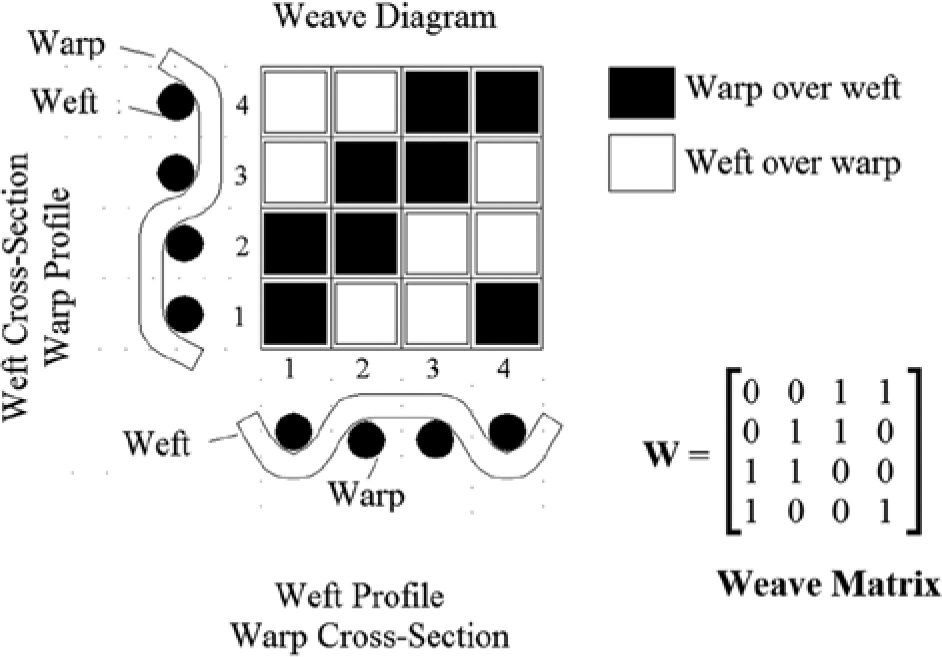
The pattern representing the warp and weft interlacement is called the weave diagram or fabric weave (Adanur, 2000), as illustrated in Figure 1. Besides this graphical representation, a mathematical representation of weave in the form of a W binary matrix of 0 and 1 can be used (Lourie, 1973; Newton & Sarkar, 1979; Pourdeyhimi, 1989). In this representation, each element is expressed by w(x,y) which provides the interweaving between a warp and a weft at the crossover (x,y). The element w(x,y) = 0 if a weft goes over a warp and w(x,y) =1 if a warp is over a weft as represented in Figure 1.
Graphical and mathematical representation of weave.
Figure 2 shows double fabric weave composed of two single layer weaves (the upper layer and the lower layer), each has own specifications.
Double woven fabric.
To obtain stitched double fabric, these two layers must be bonded together by a certain number of points called stitches. Various types of stitching can be distinguished (Elnashar & Dobnik-Dubrovski, 2008; Goerner, 1989) as follows:
Self-stitching and double stitching: These two ways were studied by Chen and Potiyaraj (1999a) and in a different way by Ping and Lixin (1999), and mathematic and programmatic modules have been developed.
Center warp stitching: This method was studied by Ping and Lixin (1999) based on the application of Kronecker product, and will be described differently in detail in this article and a programmable mathematic module will be done.
Other stitching ways may be used for binding the two layers as center weft stitching, using an intermediate fabric, warp or weft interchange with interlacing, and so on.
Indeed, except in technical fabrics, the purpose of the stitching points are not always to join together two fabrics, but they also play a decorative role.
It can be noticed that the warp and weft arrangements control the positioning modality of threads of each layer in the weave according to the fabric specifications. Figure 3 illustrates a non-stitched double weave with warp arrangement 2:1 and with weft arrangement 1:1; meaning that the upper and lower layer warps are arranged in the proportion of two upper layer ends to one lower layer end, and the upper and lower layer wefts are placed alternately in the ratio of one pick for each layer. When the two weaves are combined, repeating design will be produced on the warps in the ratio of two repeats of the upper layer weave and one repeat of the lower layer weave. The weave produced from the combination of the two single layer weaves is called extended double fabric weave.
Non-stitched double fabric with different arrangements.
It can be noticed that if only the double fabric face and back have technical or visual significance, it is necessary to seek the possible stitching points and plot them according to this condition.
In this article, the described programmable mathematic module takes into account the case where the fabric face and back weaves are previously defined where the stitches are introduced by extra warps.
Center Warp Stitching
In case of double fabric stitched by center warps, we can distinguish two types of stitches, the first is called an upper stitch symbolized by (X) where the center warp lift over the upper layer weft, and the second is called a lower stitch represented by means of the symbol (O) produced when the center warp is under the lower layer weft. The center threads stay in a horizontal position between upper and lower layers when not used for stitching (Goerner, 1989).
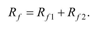
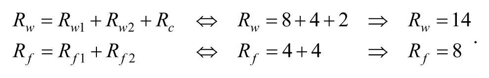
Figure 4 illustrates a double fabric stitched by center warps, constructed of 2/2 Z twill upper layer weave with an arrangement of 2 warps/1weft and 2/2 Z twill lower layer weave with an arrangement of 1warp/1weft and stitched by tow center warps located on ends 6 and 13. Lifters (↗) indicate upper layer ends over lower layer picks and center ends over lower layer picks. The transferring of weave is shown in Table 1.
Double woven fabric stitched by center warps.
Weave Transferring.
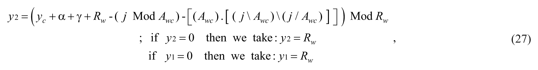
Top fabric warps
2
2
.
2
2
.
= 8
Bottom fabric warps
1
.
1
1
.
1
= 4
Center warps
.
1
.
.
1
.
= 2
Extended Weaves Generation
As mentioned above, the first step consists in defining the upper and lower layer weaves as follows:
Aw1, Af1, rw1, rf1: the warp and weft arrangement and the warp and weft repeats, respectively, for the upper layer.
Aw2, Af2, rw2, rf2: the warp and weft arrangement and the warp and weft repeats, respectively, for the lower layer.
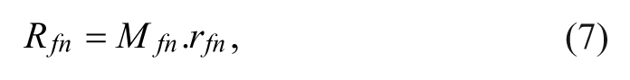
Then, identifying the center warps used for stitching by determining the center thread repeat and arrangement (rc and Ac). The total number of Rc center threads can be calculated as follows:
Based on Chen and Potiyaraj (1998, 1999a) the extended weaves of each layer, can be calculated by the following equations:
where
for the upper fabric and for the lower layer,
: the numbers of upper and lower layer weaves repeats, respectively, in the warp direction,
: the numbers of upper and lower layer weaves repeats, respectively, in the weft direction,
: the smallest number that makes this relation equal to zero:
: the smallest number that makes this relation equal to zero:
and “Mod” is the remainder operator for division.
The warp and weft repeats of the extended upper and lower layer weaves can be calculated from these equations:
where,
are the warp and weft repeats of the extended upper weave, respectively.
are the warp and weft repeats of the extended lower weave, respectively.
As 2D binary matrix, these two extended upper and lower layer weaves can be denoted by ET and EB, respectively, and the elements of these matrices are and , respectively. The warp and weft repeats of each extended weave represent the corresponding matrix size.
Inserting the upper and lower layer weaves matrix elements and into the corresponding extended matrices is achieved by
All binaries (x,y) values formed from each binary (i, j) are calculated by the following formulas:
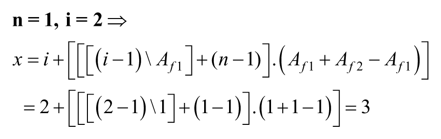
In the example shown in Figure 4, the two single layers have the following parameters:
Upper layer weave:
Lower layer weave:
From Equations 2 to 7, the following results are obtained:
Based on Equations 8 to 11, that is, to put the element into the matrix ET we have to find all (x,y) binaries values resulting from the binary value as follows:
The (x,y) binary values resulting from the binary value are (2, 7) and (2, 3), which represent the elements and consequently gives
In a similar method, we can complete all elements of the extended matrices (ET, EB) as follows:
To find the dimensions of the extended weave matrix , these formulas can be used:
To insert all the upper and lower layer threads and center warps into the extended weave W, a matrix called warps order matrix D have to be identified.
Warps Order Matrix
In Figure 4, it can be noted that the warp ends can be numbered from 1 to 14. Designating each warp from the upper fabric T, lower fabric B, and Center warp C, the warps numeration table can be deduced (Table 2).
Warp Numeration Table for T.C.B Order.
1
2
3
4
5
6
7
8
9
10
11
12
13
14
T
B
T
C
B
T
B
T
C
B
In the warps numeration table, we can distinguish that the center warp is between the upper and lower warps. Hence, warps order T.C.B can be deduced. Then warps numeration table may be transferred into warps order diagram as shown in Figure 5.
Warps order diagram in case of T.C.B order.
This warps order diagram consists in three rows and Mw columns, where Mw are calculated from Equation 3. The first row indicates the upper layer warps and the second row specifies the center warps whereas the third row is for the lower layer warps.
The warps order diagram can be transferred into a binary matrix D of 0 and 1 having the same diagram dimensions, where each element of this matrix is represented by d(c,m).
Another warps order T.B.C may be observed in double fabric stitched by center warps. In the warps order diagram corresponding to T.B.C order, the first row indicates the upper layer warps and the second row is specified for the lower layer warps whereas the third row is for the center warps, as illustrated in Figure 6. In this case, the warps numeration table is shown in Table 3,
Double fabric stitched by center warps in T.B.C order.
Warps Numeration Table for Order T.B.C.
1
2
3
4
5
6
7
8
9
10
11
12
13
14
T
B
T
B
C
T
B
C
T
B
and the warps order matrix is:
Threads Insertion in Extended Weave W
Upper and Lower Layer Threads Insertion
Each element from the extended upper and lower weave matrices ET and EB will be inserted in the matrix W as follows:
Each warp (j) will be put in the extended weave W as follows:
The parameter K is calculated from the following equation:
where:
It can be noted that in all equations, if warps are in T.C.B order and if warps are in T.B.C order.
Center Warps Insertion
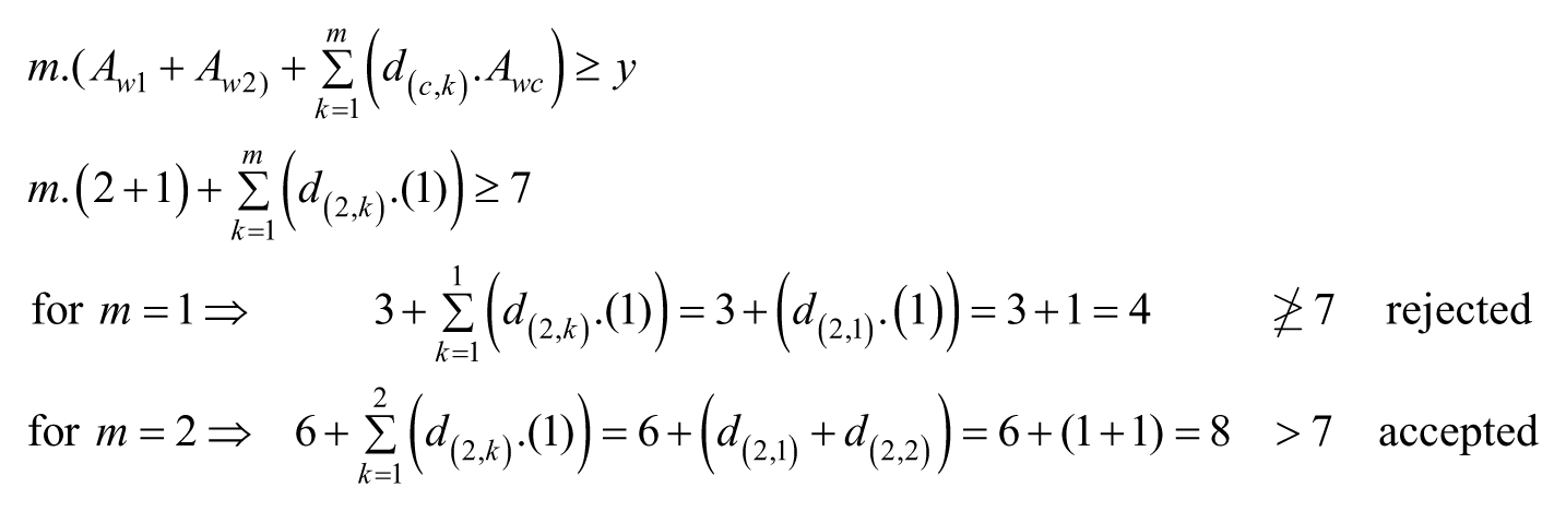
To insert each center warp j (where j = 1, 2 . . . Rwc) in the matrix W, the smallest number(s) which carries out the following inequality has to be found:
Then, the following equation is applied to put in the warp j into the matrix W:
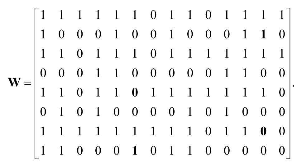
Based on Figure 4, the extended upper and lower layer matrices (ET and EB) were calculated based on T.C.B order and the D matrix was found. Other parameters were deduced as follows:
The size of extend matrix W is calculated from Equations 12 and 13 as follows:
Insertion of the element in the matrix W is done according to Equations 16, 17, and 18 as follows:
Then we find that
.
Insertion of the element in the matrix W is done according to Equations 16, 17, and 18 as follows:
Then we find that .
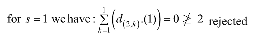
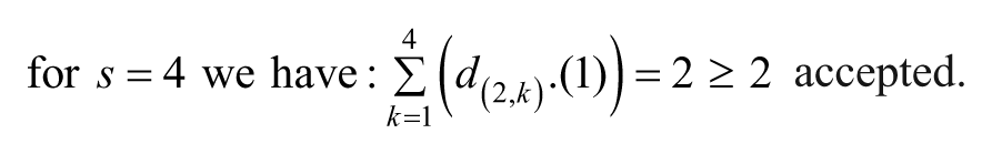
Now, we insert the center warp into the matrix W according to Equations 19 and 20 where the number (s) has to be first found:
From Equation 20, we find
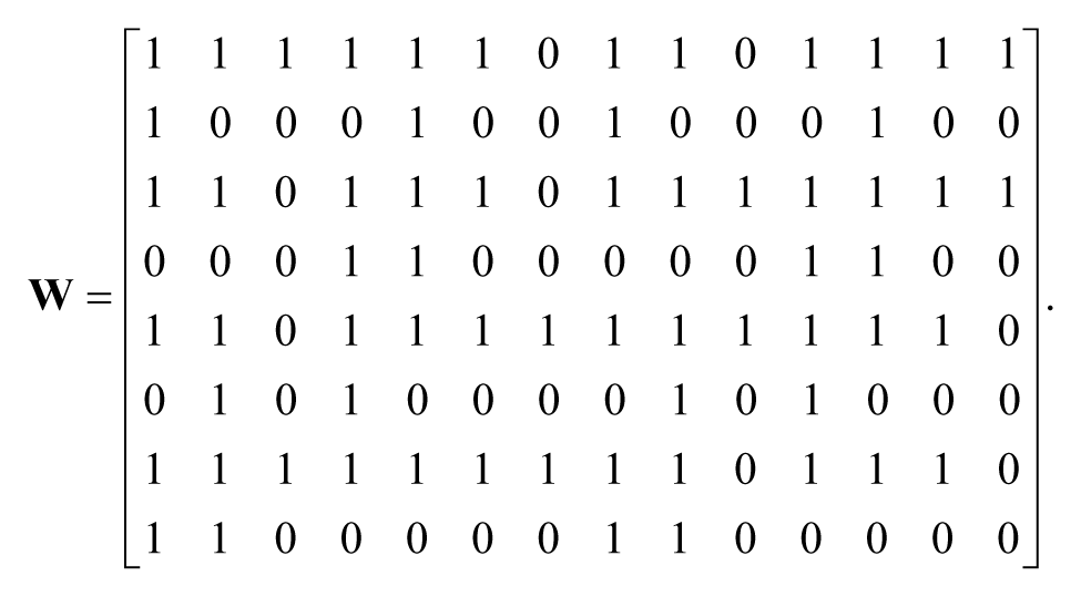
In the same way, the whole W matrix can be formed given as follows:
Lifters
Lifters in a double fabric stitched by center warp indicate that upper layer ends or center threads are over lower layer picks. Identifying the lifters and placing them in the W extended weave matrix require the determination of layers to which x and y of the w(x,y) belong.
Therefore, for each warp y, the first step is to find the smallest number m which verifies the following inequality:
Then, we calculate the warp layer identifier p from the following equation:
The second step is to calculate weft layer identifier q as follows:
Five layer identifier conditions have to be imposed for p and q to determine the layer to which x or y belongs, they are
According to the lifters definition, if x belongs to the lower layer and y belongs to the upper layer or to the center warp, then the intersection represents a lifter giving .
Weaving the upper layer separately (i.e., without stitching between the two layers) requires keeping the lower and center ends without raising during the insertion of the upper wefts. Then, if x belongs to upper layer and y belongs to lower layer or center warps, the element . These conditions are summed up in Table 4.
Lifter Conditions.
n(x)
n(y)
w(x,y)
1
2
0
No Lifter
3
2
1
1
Lifter
3
For example, to complete the matrix W produced above, taking into account the elements and , lifters have to be verified according to lifter conditions shown in Table 4.
First: for element where , from Equation 21, the smallest number m must be found:
Then, this inequality is verified when .
The layer identifier conditions mentioned previously have to be found according to the fabric parameters. The conditions are:
. Then, the current x belongs to upper layer and n(x) = 1.
. Then, the current x belongs to lower layer and n(x) = 2.
. Then, current warp y belongs to upper layer and n(y) = 1.
. Then, the warp y belongs to lower layer, and n(y) = 2.
. Then, this warp y belongs to center warps and n(y) = 3.
For the warp , the warp layer identifier p is calculated from Equation 22:
For the weft , weft layer identifier q can be calculated from Equation 23:
In comparison with the layer identifier conditions, it can be noted that the warp belongs to the lower fabric and n(y) =2, while the weft belongs to the upper fabric and n(x) =1.
Then, according to lifter conditions, we find that and then and no lifter is made in this intersection.
Second: for element where , following the same steps, we find as follows: .
In comparison with the lifter conditions, we find , then and lifter is made in this intersection.
The following matrix W can be found from lifter determination for all matrix elements discussed above:
This matrix represents the upper and lower layer weaves and the center warps. The stitching of the two layers by center warps is not yet made.
To determine to which layer the element x belongs (n(x)th) and its position (ith) in that layer, the following equation can be used:
In a similar method, y warp represents the jth warp of the n(y)th layer and j can be calculated as follows:
where and the parameter m are calculated from Equation 21.
For verifying the above equations, based on the element calculated previously, where:
Then, the fifth row of the matrix W represents the third weft of the upper layer and the seventh column of the matrix W represents the second warp of the lower layer.
Stitches determination
To obtain a double fabric stitched, stitches have to be introduced among the two layers by means of center warps. The upper stitch takes place on the upper layer (center warp over upper layer weft), represented in the weave diagram as (x). In this case, the element w(x,y) takes the value 1 in the matrix, inducing and x belongs to upper layer (n(x) = 1).
Contrarily, the lower stitch is always on the lower layer (lower layer weft is over the center warp). The symbol (O) is used to indicate this stitch in the weave diagram and the value (0) is given to the element w(x,y) in the matrix, inducing and x belongs to lower layer (n(x) = 2). This stitch can be obtained by canceling the lifter corresponding to these coordinates.
To make stitches, we have to put some conditions. Considering that is a center warp of the matrix W is to be bonded to the nth layer (upper or lower layer) with the assumption that the stitch is to be made at the crossover corresponding to the element. From the warp point of view, stitch have to be after or before adjacent [ or ] warp ends, or between two adjacent [ and ] warp ends on the same layer n to which the weft x belongs.
All conditions cited previously can be illustrated in Table 5, in which the following parameters and symbols have to be defined:
represents the center warp presented in the matrix W, it is calculated from Equations 19 and 20 for .
n(x) is the layer to which the weft x belongs. It can be identified from Equation 23 and the layer identifier conditions.
and are two consecutives warps from the same layer, between them a stitch may be produced by the center warp. These two warps are calculated from the following equations:
Stitches Conditions.
Warp order
n(x)
n(y1)
w(x,yc)
Type of stitch
T.C.B
1
1
1
1
1
upper stitch
1
0
0
1
T.B.C
2
2
0
0
0
lower stitch
1
0
0
1
Parameters
,
Warp order
n(x)
n(y1)
w(x,y1)
w(x,y2)
w(x,yc)
Type of stitch
T.B.C
1
1
1
1
1
upper stitch
1
0
0
1
T.C.B
2
2
0
0
0
lower stitch
1
0
0
1
Parameters
,
where α, β, γ are parameters depending on the warps arrangements, warps order, and , they can be found from Table 5.
is the layer to which the warp belongs. Equation 22 can be applied to identify this layer, knowing that belongs to same layer of .
Example: To carry out the stitching by the center warp (where ranges from 1 to ), we have to insert this warp in the matrix W using Equations 19 and 20. We deduce that .
Now, taking the intersection , where , and from Equation 23, we can find that .
Knowing that the warps in T.C.B order and , we find from Table 5 that , and .
Then all the intersections have to be equal to 1, that is, , this intersection represents an upper stitch.
In the same way, we can find all possible stitches in the W matrix for .
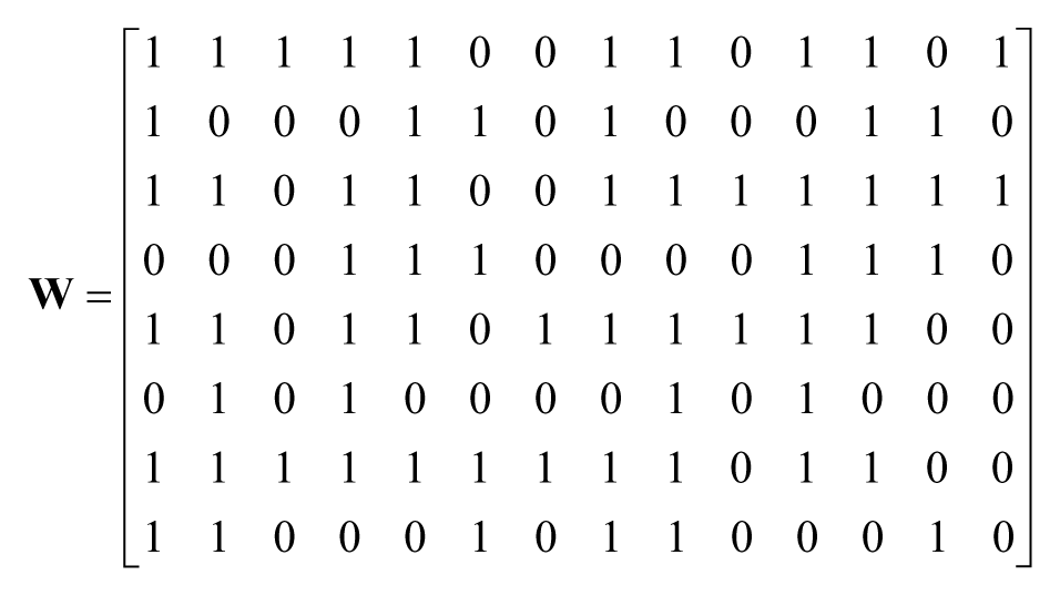
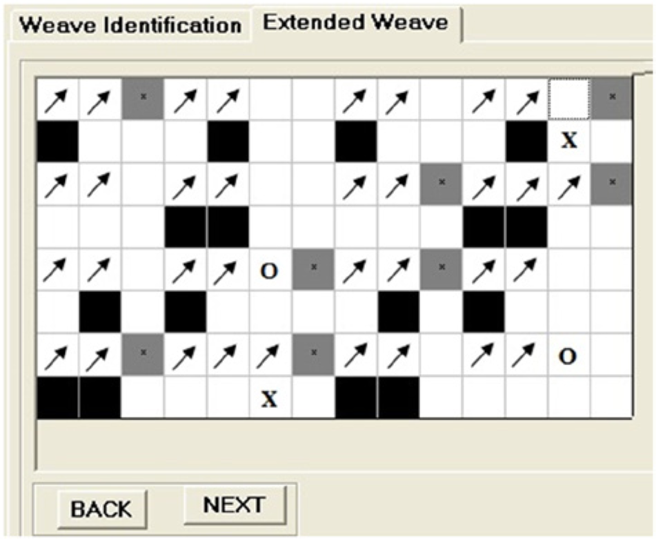
This W matrix represents the double woven fabric shown in Figure 4 with all possible stitch points represented in the following intersections:
The W matrix gives the maximum stitch points available. But, the user could choose the stitches according to the density of stitch points required in the final weave. For example, we choose two upper stitches in the intersection and and two lower stitches represented by the elements and and the other intersections automatically come back to non-stitching position:
Description of the Programmatic Module
In the implanted program, the first step is to define all fabric parameters such as threads arrangements and upper and lower weave repeats, in addition to the center warps arrangement and repeat. The weaves diagrams and warps order diagram will be automatically created according to the inserted parameters. To obtain the upper and lower weaves, the designer has to click on the square for filling it if warp is to be over weft and leave a square blank if the intersection represents the warp under the weft. Warps order diagram has to be marked according to the threads’ position required in the final weave. Figure 7 represents the interface for identifying and designing the double fabric given in Figure 4.
Interface for identifying the weaves parameters and warps order diagram.
The weave will be automatically calculated and the double fabric weave with all possible stitches will be generated and shown in another window (Figure 8). After the selection of required stitch points, the final double fabric weave will be generated and visualized in a separate window as shown in Figure 9.
The generated double fabrics weave with all possible stitches.
The final double fabric weave.
Conclusion
Double woven fabrics is a type of compound woven structure composed of upper and lower layers stitched between them by various ways such as self-stitching, double stitching, center warp stitching, center weft stitching and so on. The double cloth stitched by center threads has been mathematically described and automatically generated by developing of mathematical programmable module. In this program, after identification of this double fabric (warp and weft repeat, threads arrangement, warps order matrix), an extended weave will be created, showing all lifters and all possible stitch points. The designer will select the stitch points required to automatically create the final weave diagram which is ready to be transferred to the weaving machine after the calculation of draft and lifting plans.
Footnotes
Declaration of Conflicting Interests
The author(s) declared no potential conflicts of interest with respect to the research, authorship, and/or publication of this article.
Funding
The author(s) received no financial support for the research and/or authorship of this article.
Author Biographies
Moussa Alali was born in Syria in 1979. He graduated from the Faculty of Mechanical Engineering - University of Aleppo-Syria in 2002, and obtained his PHD in mechanical engineering from University of Haute Alsace-French in 2012. He has now a PostDoc position at LPMT-UHA-French.
Jean-Yves Drean is a Full Professor and Director of the Laboratory of Physics and Mechanics Textiles (LPMT) at ENSISA- University of Haute Alsace - French. Email: jean-yves.drean@uha.fr. URL laboratory:
ChenX. (2011). Mathematical modelling of 3D woven fabrics for CAD/CAM software. Textile Research Journal, 81, 42-50. doi:10.1177/0040517510385168
3.
ChenX.KnoxR. T.McKennaD. F.MatherR. R. (1996). Automatic generation of weaves for the CAM of 2D and 3D woven textile structures. Journal of the Textile Institute, 87, 356-370. doi:10.1080/00405009608659088
4.
ChenX.PotiyarajP. (1998). CAD/CAM for complex woven fabrics. Part I: Backed cloths. Journal of the Textile Institute, 89, 532-545. doi:10.1080/00405009808658639
5.
ChenX.PotiyarajP. (1999a). CAD/CAM for complex woven fabrics. Part II: Multi-layer fabrics. Journal of the Textile Institute, 90, 73-90. doi:10.1080/00405009908658692
6.
ChenX.PotiyarajP. (1999b). CAD/CAM of orthogonal and angle-interlock woven structures for industrial applications. Textile Research Journal, 69, 648-655. doi:10.1177/004051759906900905
7.
ElnasharE. A.Dobnik-DubrovskiP. (2008). The influence of the weave and the method of stitching on selected mechanical properties of woven double fabrics. AUTEX Research Journal, 8, 41-43.
8.
GoernerD. (1989). Woven structure and design—Part 2: Compound structures (1st ed.). Manchester: British Textile Technology Group.
9.
LiaoT.AdanurS. (1998). A novel approach to three-dimensional modeling of interlaced fabric structures. Textile Research Journal, 68, 841-847. doi:10.1177/004051759806801109
10.
LomovS.PerieG.IvanovD.VerpoestI.MarsalD. (2011). Modeling three-dimensional fabrics and three-dimensional reinforced composites: Challenges and solutions. Textile Research Journal, 81, 28-41. doi:10.1177/0040517510385169
11.
LourieJ. R. (1973). Textile graphics/computer aided. New York: Fairchild Publications.
12.
NewtonA.SarkarB. P. (1979). An analysis of compound weaves. Journal of the Textile Institute, 70, 427-438. doi:10.1080/00405007908658882
13.
PingG.LixinD. (1997). Study of the mathematical model for fabric weave design and its applications. Journal of the Textile Institute, 88, 265-281. doi:10.1080/00405009708658550
14.
PingG.LixinD. (1999). Algorithms for computer-aided construction of double weaves: Application of the Kronecker product. Journal of the Textile Institute, 90, 158-176. doi:10.1080/00405009908690620
15.
PourdeyhimiB. (1989). Programming techniques in computer-aided design of woven fabrics. Journal of the Textile Institute, 80, 391-401. doi:10.1080/00405008908658294
16.
SmithM.ChenX. (2009). CAD/CAM algorithms for 3D woven multilayer textile structures. International Journal of Mechanical Systems Science and Engineering, 3, 30-41.