
Abstract
Introduction
Geriatric patients who suffer femoral neck fractures have high morbidity and mortality. Prophylactic fixation of the femoral neck is a potential avenue to reduce the incidence of femoral neck fractures. We studied 3 different implants traditionally used to stabilize the femoral neck: 6.5 mm cannulated screws (CANN), the femoral neck system (FNS) (Depuy Synthes), and the dynamic hip screw (DHS) (Depuy Synthes).
Materials and Methods
Five osteoporotic Sawbone femurs were used for each model and a control group. Two scenarios were investigated: single leg stance to measure construct stiffness and lateral impact to measure construct stiffness, energy to fracture, and qualitative examination of fracture patterns. Stiffness for each femur and energy to fracture for the lateral impact scenario were calculated and compared between groups using one-way ANOVA.
Results
DHS showed significantly higher stiffness than the other 2 implants and the control in single leg stance. In the lateral impact scenario, the DHS and CANN were significantly stiffer FNS and the control. Femurs implanted with CANN tended to fracture at the greater trochanter while FNS fractured in a transverse subtrochanteric pattern, and DHS fractured obliquely in the subtrochanteric region.
Discussion
FNS and DHS experienced fracture patterns less amenable to surgical correction. CANN and DHS proved better able to resist external forces in the lateral fall scenario. CANN also proved better able to resist external forces in the single leg stance scenario and experienced a more amenable fracture pattern in the lateral fall scenario.
Conclusions
FNS was less able to resist external forces compared with the other implants. This work informs the potential implications between the choice of implants that, although historically have not been used prophylactically, may be considered in the future for prophylactic stabilization of the femoral neck. Cadaveric study and clinical trials are recommended for further study.
Introduction
The prevention of geriatric hip fractures is an ever-increasing topic of interest to physicians. 1 Falls resulting in hip fractures represent a significant cause of morbidity and mortality among geriatric patients. 2 Understanding osteoporosis and its management are key to prevention.3,4 Fractures of the femoral neck are a particularly important subset of geriatric femur fractures. Current literature describes prophylactic femoral neck stabilization in cases of pathologic lesions due to tumor or metastasis.5,6 However, implantation of a medical device to prevent a femoral neck fracture in a patient who is at high risk of falls and suffers from osteoporosis is a topic that has not received much attention in the literature, except for 1 notable exception is a review article published by Varga et al 7 which unfortunately found existing prophylactic solutions unsatisfactory.
In a previous work, a finite element analysis study was performed on cannulated screws (CANN) in the context of prophylactic implantation in simulated osteoporotic bone. 8 This yielded positive results for lateral fall/impact scenarios, decreasing volumetric failure (percentage of failed constituent elements in a simulation), depending on bone density, from 11% to 21%. For a single leg stance scenario, CANN screws acted as stress risers by translating applied loads in the femoral head to higher stresses in the lateral cortex of the femoral neck.
Here, we compare the biomechanical fidelity of 3 different types of hip implant designs: CANN, the femoral neck system (FNS), and the dynamic hip screw (DHS) (Figure 1). We studied these 3 different implant types under 2 different loading conditions: (1) single leg stance to body weight to measure construct stiffness, which is performed as a baseline to simulate the load of a standard adult human; and (2) lateral impact to fracture, simulating the impact on the lateral aspect of an osteoporotic patient’s femur, to measure construct stiffness, measure energy to fracture, and qualitatively examine the resultant fracture patterns. Our goal is to understand which type of implant is better suited to protect the proximal femur from physiological and fracture-inducing loads. Three methods of femoral neck stabilization used in this study: (A) cannulated screw, (B) femoral neck system, and (C) dynamic hip screw.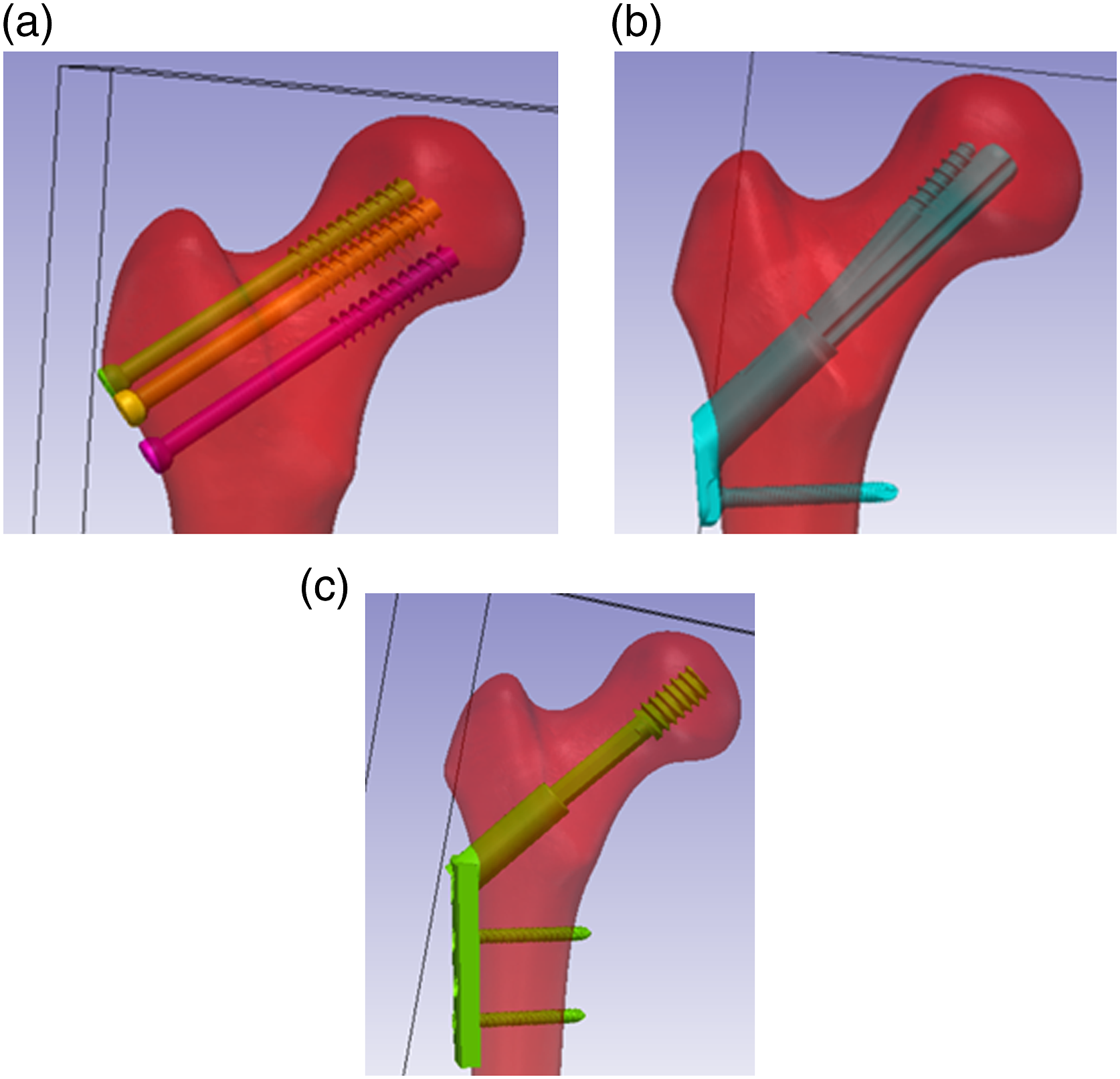
Methods
Design of Drill Guides
Using Simpleware ® ScanIP 3D Modeling Software (Mountain View, CA, USA), 3 custom 3D printed guides for aiming and drilling guide wires for implanting CANN, FNS and DHS were designed in consultation with our orthopedic surgical authors, each of which has more than 5 years of post-fellowship practice. The goal of these guides was to ensure that guide wires were placed uniformly across groups. Guides were designed according to each manufacturer’s technique guide specifications of angle of entry with a 130° angle with respect to the diaphysis in FNS 9 and a 135° angle with respect to the diaphysis in DHS. 10 The positioning of the CANN guide wires was performed according to AO Trauma surgical principals. 11 All guides were created with the specified diameter of each implant’s system (2.8 mm for CANN, 3.2 mm for FNS, 2.5 mm for DHS) These guides were printed using the Form3BL 3D Printer from FormLabs® (Somerville, MA, USA). Once the guide wires were positioned in the osteoporotic femur models, we confirmed accurate guidewire placement by performing CT scans on all Sawbone femurs and compared position and angle of entry of the guide wire in the osteoporotic Sawbone with the planned placement of the guide wires to ensure accuracy. Placement was compared to other works of guide wire placement and proved to be within tolerances (less than 10°) of position angle of entry into the femoral cortex, as shown in previous work.12,13
For each implant, we implanted 5 osteoporotic Sawbone femurs (Osteoporotic Femur, Composite, 10 PCF Solid Foam with 16 mm Canal, Medium) (Vashon Island, WA, USA). All implants were positioned by an orthopedic trauma fellow. We also conducted the tests on 5 osteoporotic Sawbones without implants as a control group.
Implantation of Cannulated Screws
The CANN implants were implanted in 5 osteoporotic Sawbone femurs (Osteoporotic Femur, Composite, 10 PCF Solid Foam with 16 mm Canal, Medium). With the CANN 3D printed drill guide, 3 2.8 mm diameter guide wires were implanted by a trauma fellowship trained orthopedic surgeon using a Stryker System 7 wire driver power system across all implants. CT scans were taken of all 5 of the osteoporotic Sawbone femurs and accurate placement of the guide wires was confirmed with the 3D modeling software. This has been confirmed in previous work on 3D modeling software and 3D printing. 13 Three cannulated partially threaded 6.5 mm diameter screws (Depuy Synthes) were implanted on top of the guide wires, removing the guide wires when finished.
Implantation of Femoral Neck System
The FNS implants were implanted in 5 osteoporotic Sawbone femurs based on the manufacturer’s specification with regards to the surgical technique guide. 9 First, the 3D printed drill guide was attached to the Sawbone. Then the 3.2 mm guide wire was implanted. To confirm accurate placement of the guide wires in all 5 of the FNS samples, CT scans were taken, and the wire trajectories were examined with image processing software. Once confirmed, implantation of the FNS was performed. The path of the guide wire through each osteoporotic Sawbone femur was reamed. The titanium (TiAl6Nb7 [TAN]) bolt was inserted into the stainless-steel plate. The system was implanted using an FNS insertion handle. The bolt-plate system was secured transversely with a locking screw, followed by the anti-rotation screw, torqued according to manufacturer specifications.
Implantation of Dynamic Hip Screw
Five osteoporotic Sawbone femurs had the DHS system implanted using the manufacturer’s technique guide. 10 First, using the 3D printed DHS guide, a 2.5 mm guide wire was implanted. CT scans were taken of the 5 osteoporotic Sawbone femurs with the guide wires implanted to confirm accurate placement with the 3D modeling software. Then, a triple reamer for the DHS was used to ream for the DHS screw. A stainless steel cannulated DHS screw of outer diameter 13 mm was implanted by following the path of the guide wire. The locking compression plate (LCP), was implanted using a manual impactor. The LCP was fixed to the shaft with self-tapping 4.5 mm cortex screws.
Loading Tests
Testing was performed on all 15 of the osteoporotic Sawbone femurs with implants as well as the 5 controls (without implants). All loading was performed using a servohydraulic load cell (Instron model 8874; Instron Corp, Norwood, MA, USA). Two tests were performed: a single leg stance loading to the body weight of a typical adult patient (180 lbs or 797 N) and lateral impact test to fracture. The single leg stance test was performed in load control at 797 N with load on the femoral head and the femur at 15° angle (Figure 2A).
14
The lateral impact test to fracture was performed in displacement control at 120 mm/s. A stand to hold the femoral heads during the lateral impact test was 3D printed (Figure 2B). Angle of impact was chosen as directly perpendicular to the greater trochanter as performed in previous studies.
15
Loading tests using the Instron load cell in (A) single leg stance and (B) lateral impact. The 3D printed stand is seen on the right securing the femoral head.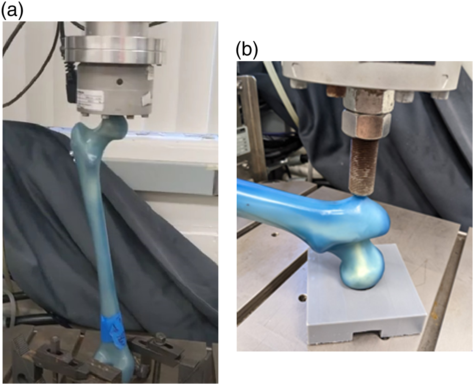
For both the baseline single leg stance and lateral fall scenarios, load vs displacement was collected at 200 Hz. Stiffness was calculated for each scenario by taking the slopes from each of the load vs displacement data during the linear phase. Energy to fracture for the lateral impact scenarios was defined as the area under the loading curve.
Statistical Analysis
Using GraphPad Prism software (GraphPad Software Inc, San Diego, CA, USA) one-way ANOVA with a Tukey’s post-hoc test for multiple comparisons was performed on the stiffness of each model within each loading scenario and the energy to fracture for the lateral impact tests. Significance was defined as P < .05.
Results
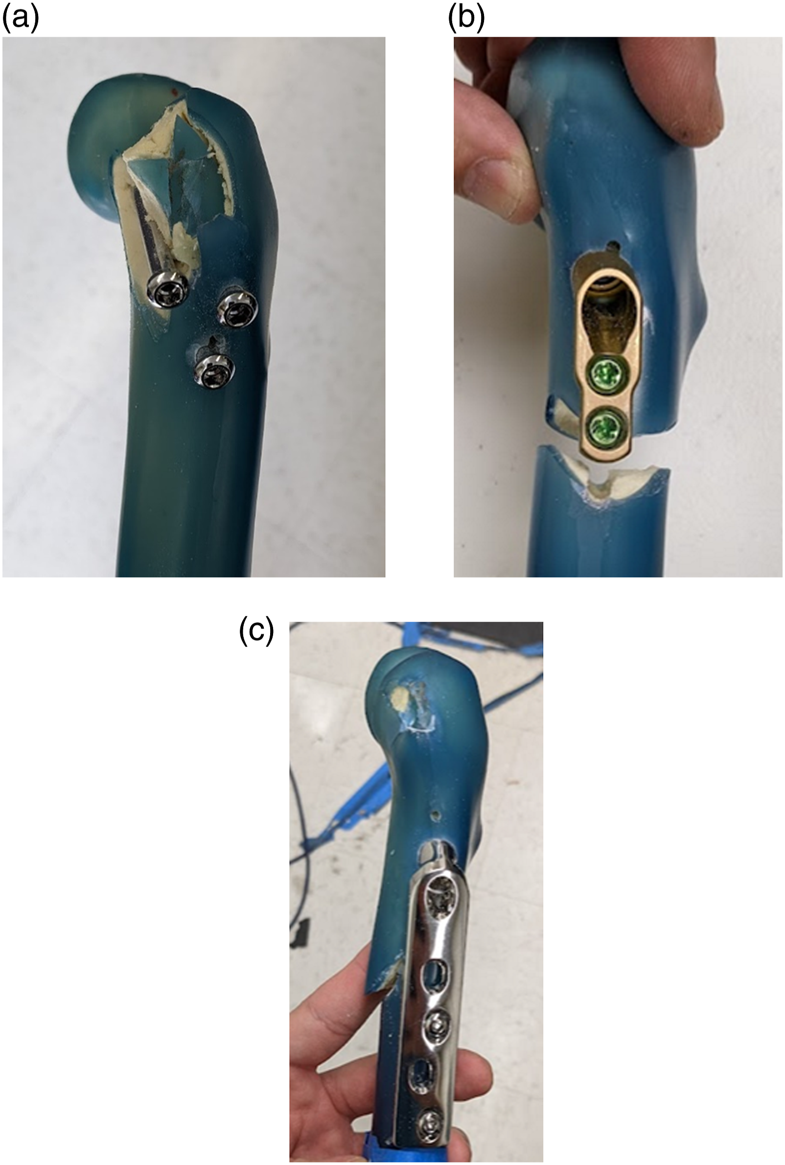
The load and displacement curves for both the single leg stance and the lateral fall impact tests are shown in Figure 3. The results showed the DHS group was significantly stiffer than the other groups in single leg stance (Figure 4A) (Table 1). Both DHS and CANN were stiffer in the lateral fall scenario (Figure 4B) (Table 1). There was no significant difference between the energy to fracture in lateral fall between groups (P = .079) (Figure 5). Fracture patterns during the lateral impact test are depicted in Figure 6 for all 3 models. Each implant had a distinct fracture pattern that was consistent among the trials. The FNS scenario demonstrated transverse subtrochanteric fractures at the level of the distal locking screw. The DHS scenarios demonstrated oblique subtrochanteric fractures. The CANN scenarios demonstrated fractures at the greater trochanter while sparing the femoral neck. The statistically significant differences, or lack thereof, between stiffnesses in the single leg stance, lateral fall, and energy to fracture in lateral fall can be seen in Table 1. Load and displacement curves for: (A) the single leg stance tests and (B) the lateral impact tests (right). For each test, representative curves are given for control, CANN, FNS, and DHS models. Average stiffnesses for: (A) the single leg stance tests and (B) the lateral impact tests. For each test, control, CANN, FNS, and DHS stiffnesses are shown. Stiffnesses (single leg stance and lateral fall) and energy to fracture (lateral fall) with statistically significant differences given for the 3 implants tested and control. Key: * different from control, d different from DHS, f different from FNS, p different from CANN. Energy to fracture for the lateral impact test, across all models. Fracture patterns in (A) CANN, (B) FNS, and (C) DHS.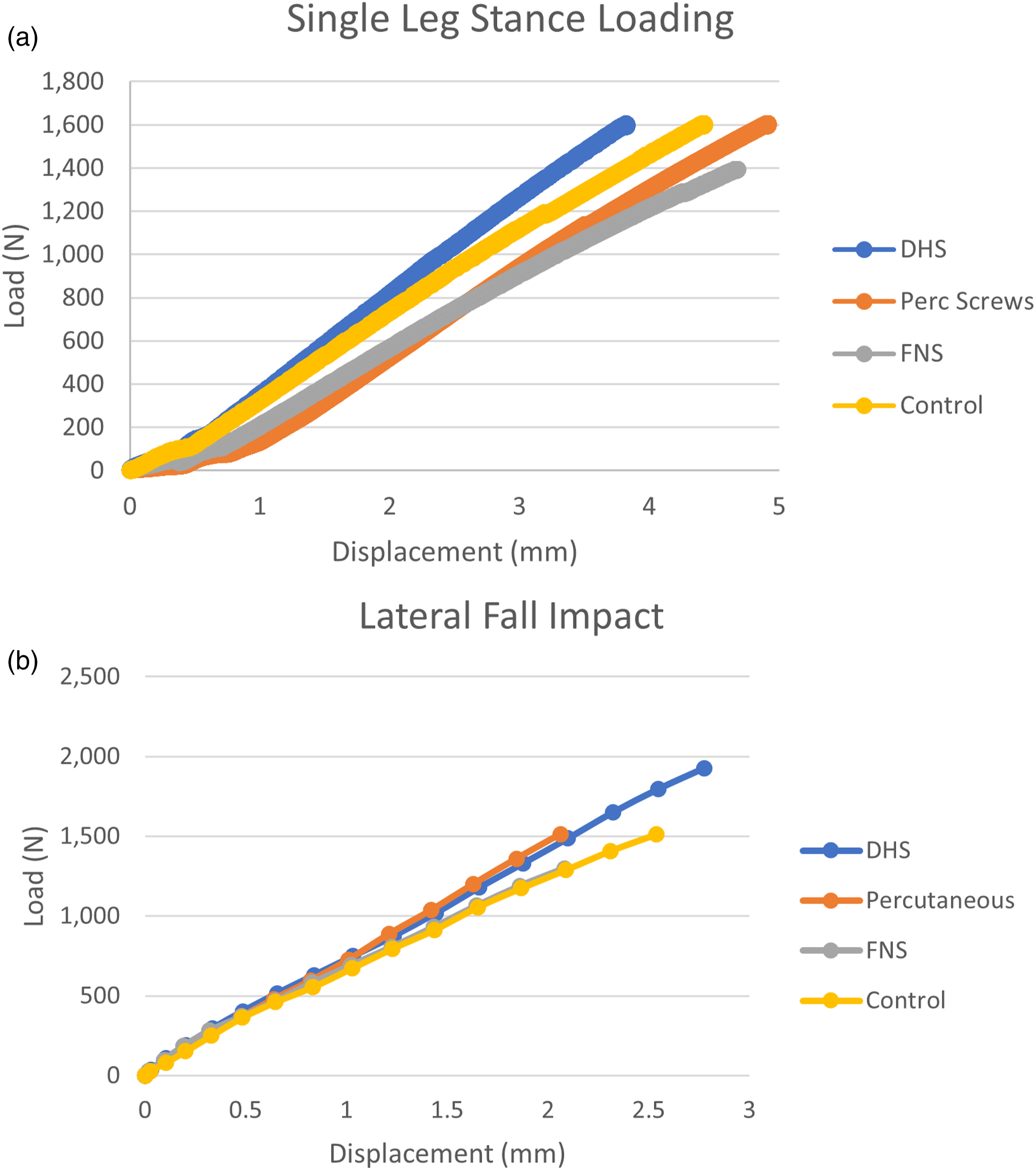


Discussion
In our assessment of 3 commonly used hip fracture implants to identify if one of these implants would be a potential candidate for femoral neck prophylactic fixation, we found that the FNS was inadequate in resisting external forces and providing stability to the femoral neck compared with the other implants and control. The FNS proved more compliant to lateral impact forces and resulted in challenging to treat transverse subtrochanteric fracture patterns. CANN, however, was stiffer and therefore provided necessary stability in the lateral fall scenario and fractured at the greater trochanter. We must note that by stiffness, we take into account the fact that stability may be provided by the implant’s location in the femur and not simply the inherent material properties that the construct provides.
In the standardized initial single leg stance tests, the DHS implant was stiffer compared to FNS, CANN, and the control. In the lateral impact scenario, DHS and CANN are stiffer and better able to resist forces which induce fracture, but DHS had a less favorable fracture pattern (subtrochanteric) compared with CANN. CANN demonstrated a greater trochanter fracture with the femoral neck remaining intact, while FNS and DHS produced subtrochanteric fracture that are more challenging to treat when compared with fracture at the greater trochanter that was observed in CANN.16,17
In a previous work using finite element analysis, in a single leg stance scenario CANN screws acted as stress risers with increased volumetric failure compared with a control finite element model. 8 This was due to a transfer of stresses from the femoral head to the lateral cortex of the femoral neck. This pattern appears to be borne out in the biomechanical tests performed here with the CANN implant being significantly more compliant (ie, significantly less stiff) compared with the DHS implant. Equally, in the prior finite element analysis, the lateral impact scenario CANN implant saw a substantial improvement in femoral neck fracture risk, with a decrease in volumetric failure between 11-21%. 8 This is borne out in our biomechanical work as well, with a significantly higher stiffness of CANN in the lateral impact scenario.
Cephalomedullary devices, as well, are currently used for prophylaxis of suspected future pathologic fractures.18,19 Others have considered its application to prophylaxis of osteoporotic-related prophylaxis of femoral neck fracture.20-22 To be sure, cephalomedullary devices provide no guarantee for protecting against peri-prosthetic fractures, but advances in cephalomedullary implants have greatly decreased this risk of fracture.23-25 Although the scope of this study involved only extramedullary devices, comparing DHS and CANN to a cephalomedullary device (both in terms of stability and risk of peri-prosthetic fracture) provides an interesting avenue for future study.
Limitations
These results are only validated for the osteoporotic Sawbone femur models. Additional work is needed using cadaveric models and, potentially, clinical trials with human subjects to determine whether outcomes for femoral neck fracture patients are significantly influenced by the type of implant that is used for stabilization. The relatively low sample size is also a limitation, particularly when considering the energy to fracture significance being so close, but still not reaching significance. Additional osteoporotic sawbone femur testing would otherwise be required to determine statistical significance. It must also be noted that the angle of impact on the greater trochanter may vary, not only in terms of angle with respect to the coronal plane, but also with the transverse plane.26,27 Therefore, the angle of impact in the lateral fall may not always reflect a realistic angle of impact.
Conclusion
Our study determined that FNS is less adequate in providing prophylactic stability to the femoral neck compared to the other implants and control. CANN, and even DHS, appear to be stiffer and better able to resist forces under lateral fall events, although DHS exhibited a less desirable fracture pattern compared with CANN. Future cadaveric study is needed to further validate the stiffness relationships of these constructs and if this is demonstrated, subsequent clinical trials in humans are needed to determine the prophylactic implants’ influence on long term patient morbidity and mortality.
Footnotes
Declaration of Conflicting Interests
The author(s) declared no potential conflicts of interest with respect to the research, authorship, and/or publication of this article.
Funding
The author(s) disclosed receipt of the following financial support for the research, authorship, and/or publication of this article: This work was supported by the National Center for Advancing Translational Sciences (UL1 TR001863).
Ethical Approval
The name of the ethics committee for approval/consent for our laboratory is Yale IRB – Yale University Institutional Review Board. No patient or animal data was collected in this study and therefore no additional approval was required.