
Abstract
A ballistic resistance of hard ceramic combined with aluminum foam sandwich (CAFS) constructions was investigated in this paper. This combination plate is constructed by a front faceplate (FFP), ceramic plates, an aluminum foam (Al-foam) panel, and a rear faceplate (RFP). The material used for the FFP and RFP was heat-treated mild steel with the thicknesses are 5 mm and 3.5 mm, respectively. The ceramic materials to be evaluated are B4C, SiC, and Al2O3. Al-foams were fabricated by varying the stabilizer weight ratio of MgO and Al2O3. The Al-foams have a porosity of 79.93%–82.57%, a pore diameter of 2.51–2.82 mm, the relative density of 0.17–0.24, and plateau stress of 3.88–6.63 MPa. Ballistic tests were carried out only for aluminum foam sandwich (AFS) construction without ceramics to evaluate the manufacturing effect and to obtain a baseline ballistic plate to be improved. Ballistic tests are conducted by using 5.56 × 45 mm bullet with 50 m shooting range and bullet speed of 929–958 m/s. To validate the damage mode and energy absorption capability of the AFS, a numerical model is constructed. The numerical studies were conducted to investigate the damage mode and energy absorption capabilities of each part. The simulation has a good agreement with the experiment result on the damage mode. This model then to be used to study the effect of the additional hard ceramic layer. An interaction between hard ceramic and AFS is also investigated to get a new insight of the energy absorption mechanism during bullet penetration. A new finding shows that ceramic presses the Al-foam to solidify so that it can increase the energy absorbed by the Al-foam. The ceramic is impacted by a bullet pushing the Al-foam so that it undergoes solidification which leads to increasing absorbed energy.
Introduction
The high-velocity impact of a projectile can penetrate a structure and endanger human lives. A protective structure is needed to stop the projectiles so that it can reduce the risk of injury or catastrophic damage. Armor plates against ballistic and blast threats based on aluminum foam have been widely studied by researchers (Gama et al., 2001; Garcia-Avila et al., 2015; Liu et al., 2017; Nia and Kazemi, 2020; Pratomo et al., 2020, 2021). A ballistic armor can be consisted of a single thick plate of high strength metal (e.g., high strength steel), but it is so heavy. To reduce the weight, the ballistic armor must be constructed as a sandwich construction that consists of various materials such as hard materials (e.g., ceramics) combined with high energy absorption materials (e.g., composites or metal foams). The sandwich construction should increase the ballistic resistance performance by superposing the key ability of each component. Therefore, this sandwich construction is expected to stop the projectile with a smaller mass. By using hard material such as ceramics, it can erode the projectile, but it has low toughness (brittle). This flaw will be assisted by using the high ductility metal as faceplates. These metals can absorb bullet kinetic energy by using the large deformation capability. And by using composite materials, it can stop the remaining bullet by catching the shrapnel and debris. Furthermore, sandwich construction is usually used in limited space and restricted weight such as in airplanes, which requires a narrow space and a lightweight structure.
An aluminum foam sandwich (AFS) consists of two metal plates (front faceplate (FFP) and rear faceplate (RFP)) and an aluminum foam core. The AFS has excellent kinetic energy absorption characteristics (Gama et al., 2001; Liu et al., 2013a; Wu et al., 2011). The aluminum foam (Al-foam) is one type of metallic foam that is often used for impact energy absorbers (Hanssen et al., 2002a; Liu et al., 2013b) due to its low density and high energy absorption capability. Constitutive models for the Al-foam have been developed (Deshpande and Fleck, 2000; Hanssen et al., 2002b; Reyes et al., 2003) for deep analysis and numerical prediction. Ballistic resistance of the AFS has also been studied without regard to the manufacturing process (Hou et al., 2010). One of the manufacturing techniques of Al-foam have been developed by using the direct foaming method with CaCO3 foaming agent and MgO & Al2O3 stabilizers (Babcsan, 2003; Curran and John, 2004). The several studies have observed the effect of the generation of MgAl2O4, which can strengthen the Al-foam cell wall (Vinod kumar et al., 2011; Guo et al., 2015). Research on ceramics as ballistic protection has also been carried out by many researchers (Liu et al., 2013a; Bracamonte et al., 2016; Dresch et al., 2021; Hazell et al., 2021) that describe the excellent ballistic resistance potential of ceramics. Studies on ceramic sandwich plates have also been carried out by many researchers (Bracamonte et al., 2016; Rahman et al., 2018; Sharma et al., 2018) that conclude in a synergistic increase in its ballistic resistance by combining ceramic and other layer such as composite plate. From the two potential materials (AFS and ceramics), it is rare to discuss the combination that may have a synergistic potential between Al-foam and ceramics. Therefore, due to the lack of studies on this phenomenon, this paper will analyze the interaction between AFS and ceramics.
In this paper, ballistic resistance of hard ceramic combined with aluminum foam sandwich constructions is investigated experimentally and numerically. Ballistic tests were carried out only for aluminum foam sandwich (AFS) construction without ceramics to confirm the manufacturing effect and to obtain a baseline ballistic plate to be improved. Then numerical models are constructed to validate and to capture the damage mode and energy absorption capability of the AFS. The validated simulation models are then used to study the effect of the additional hard ceramic layer. Three types of hard ceramic B4C, SiC, and Al2O3 are investigated to obtain the best ballistic resistance performance. The interaction between hard ceramic and AFS is also investigated to get a new insight of the energy absorption mechanism during bullet penetration. The ballistic tests give the result that the manufacturing effect (ratio of MgO and Al2O3) play a role in ballistic resistance performance due to the forming of MgAl2O4 that can increase the Al-foam mechanical properties. A new finding shows that ceramic presses the Al-foam to solidify so that it can increase the energy absorbed by the Al-foam. The ceramic is impacted by a bullet pushing the Al-foam so that it undergoes solidification which leads to increasing absorbed energy.
Experiments
Ballistic test
The ballistic experimental setup scheme to evaluate AFS firing resistance is shown in Figure 1(a). Ballistic testing was carried out using an SS1-V1 weapon that was placed on the firing holder to make the shooting direction precise on the position of the target. The velocimetry instrument was placed next to the weapon to measure the speed of the bullet. The firing passageway (Figure 1(b)) was used so that external factors such as wind did not affect the bullet movement. The shooting distance is about 50 m. The bullet velocity measurement software was EDH Muzzle Velocity Analysis Software v2.32.2 Figure 1(c). (a) Scheme of ballistic experimental setup, (b) Firing passageway, and (c) Bullet velocity-meter instruments.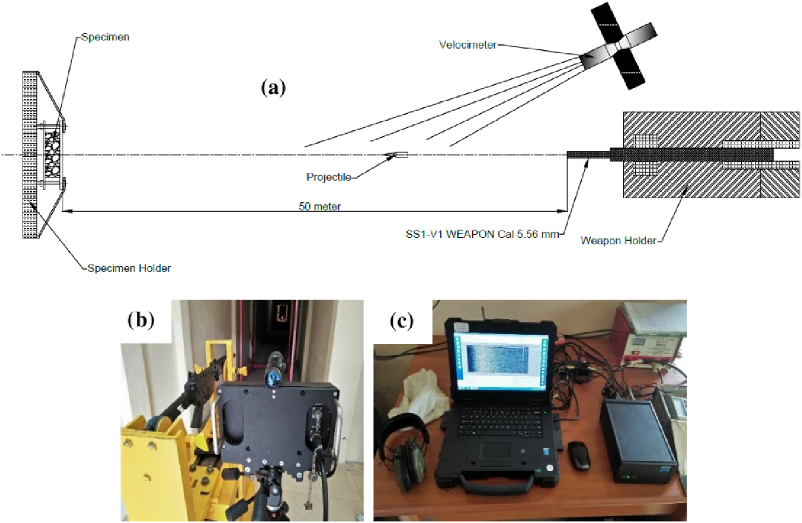
The geometry of the AFS specimen for the ballistic test is shown in Figure 2(a)–(c). An AFS specimen consisted of a cylindrical aluminum foam core that had a height of 30 mm and a diameter of 90 mm. In addition, there were also front faceplate (FFP) and rear faceplate (RFP), which had square-shape with the side length of 140 mm and the thicknesses of 5 mm and 3.5 mm, respectively. The FFP and RFP used the heat-treated steel ST-37 material. The Al-foam and the faceplates are combined with mechanical clamping using bolts and nuts (fixing bolt) on all four sides of the steel plate. On the test, the AFS specimen was mounted in the specimen holder (Figure 1(a)). Aluminum foam sandwich specimen: (a) 2D side view, (b) 2D top view, and (c) Real specimen.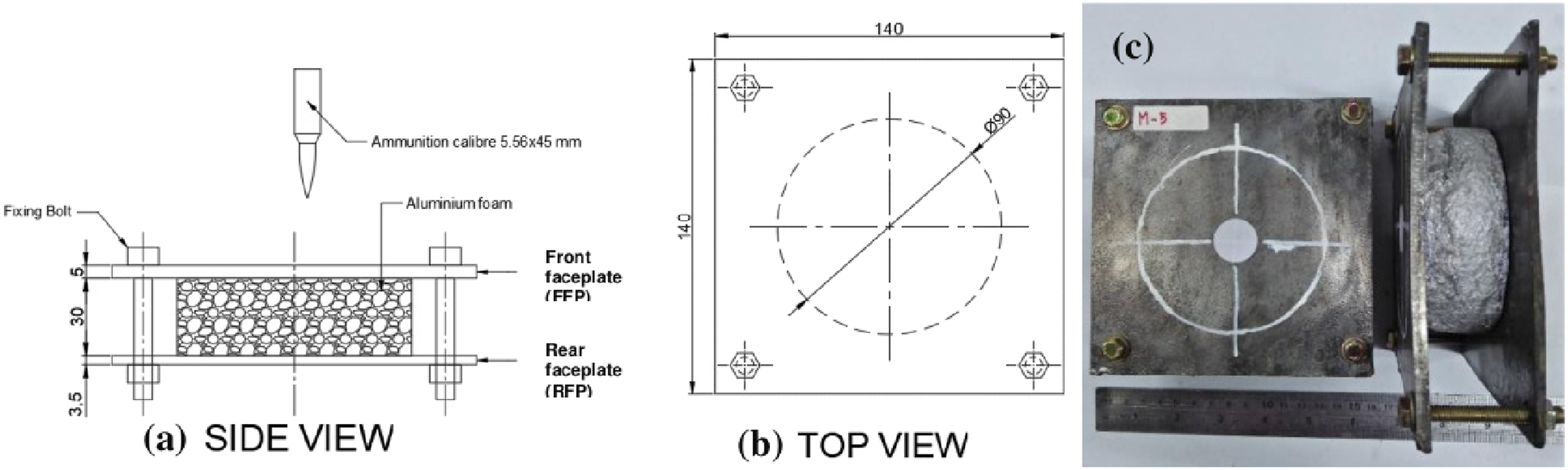
The weapon for the ballistic test is the SS1 assault rifle using 5,56 × 45 mm caliber ammunition. Figure 3(a) shows the geometry of cartridges used for the ballistic test and used for numerical modeling of the bullet. Figure 3(b) is the specification of the cartridges produced by PT PINDAD. This ballistic test was classified as a standard test according to NATO Standardization Agreement (STANAG) 4569 level 1 (NATO, 2011, 2012) in the form of the kinetic energy of 5.56 × 45 mm NATO Ball (SS109) at 30 m with a velocity of 930 m/s or equal to National Institute of Justice (NIJ) Standard about ballistic resistance of body armor (NIJ- 0108.01) level IIIa (U.S. Department of Justice, 2008). Cartridge for ballistic test; (a) Geometry and (b) Specification.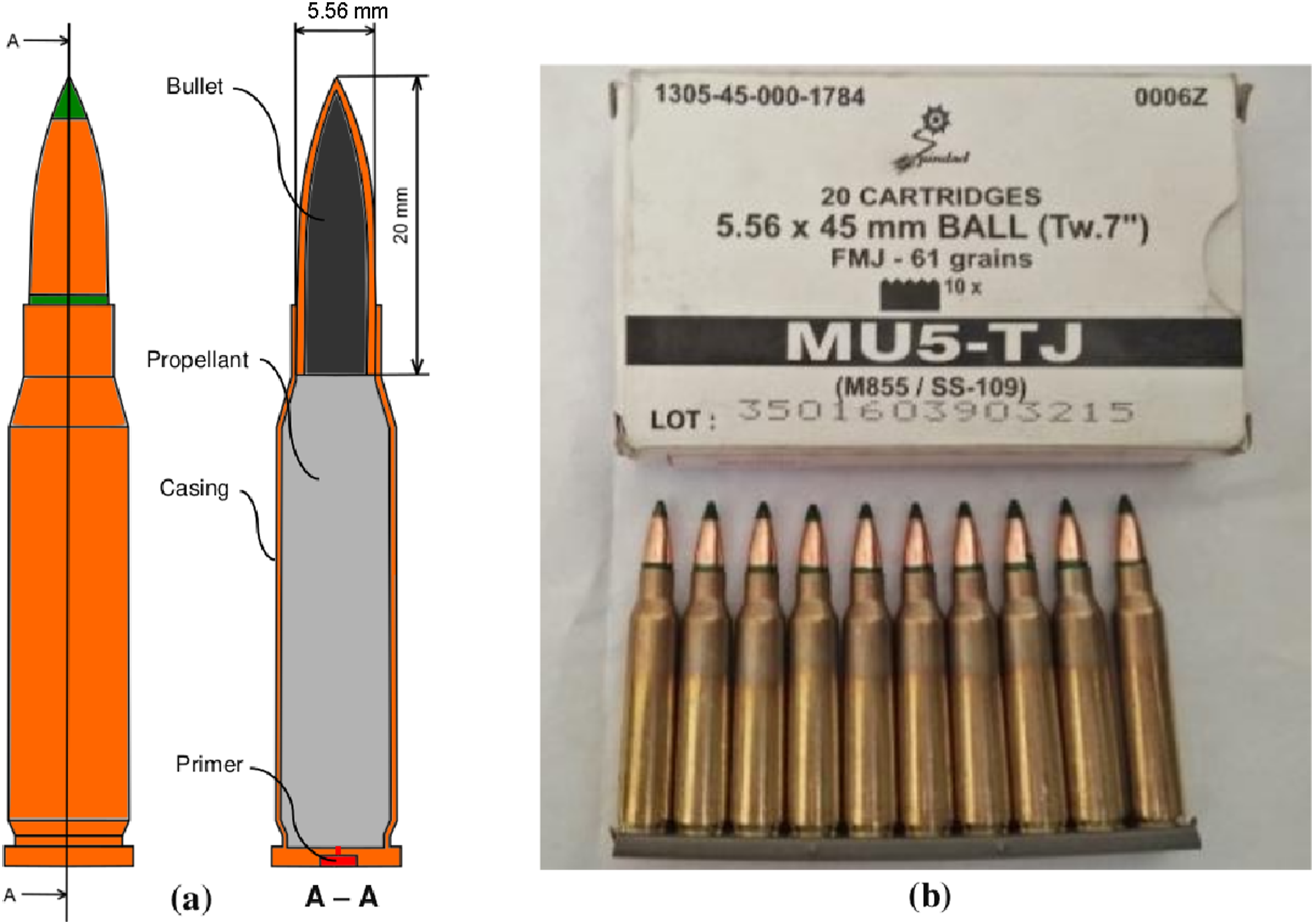
Aluminum foam fabrication
Fabrication parameters of aluminum foams.
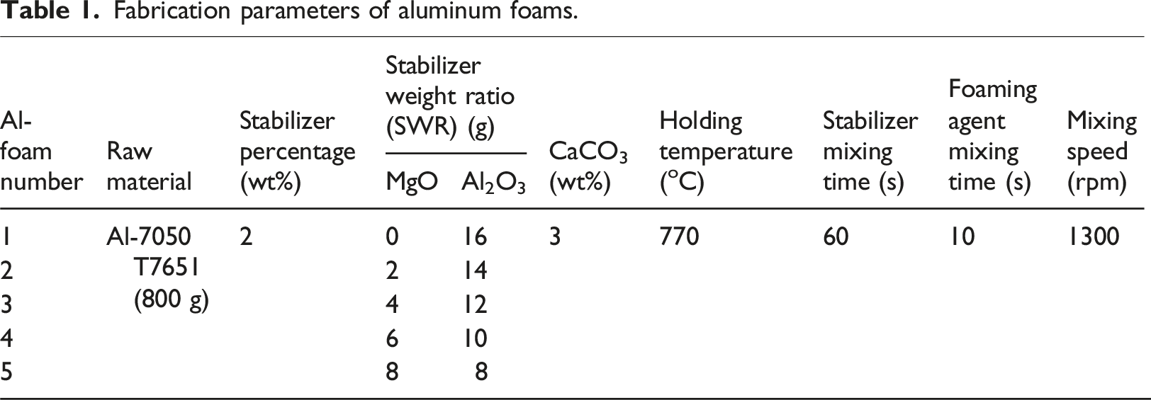
Figure 4 shows the manufacturing stages of the Al-foam. Firstly, the aluminum was heated up until melting temperature, and it is continuously controlled temperature around 770oC. Then, the stabilizers were added while stirring evenly with the mixer speed of 1300 r/min and holding time of 60 s. In this study, the stabilizers used were Al2O3 and MgO powders (Figure 4(a) (Babcsan, 2003). Then, the foaming agent (CaCO3) was added while stirring with the mixer speed of 1300 r/min and holding time of 10 s (Figure 4(b)). After a few seconds, the gas will be formed and be trapped to form air cavities (Figure 4(c)). Finally, cooling was done quickly by blowing wind, then Al-foam was removed from the mold. Aluminum foam fabrication processes; (a) Stabilizing, (b) Foaming, and (c) Cooling.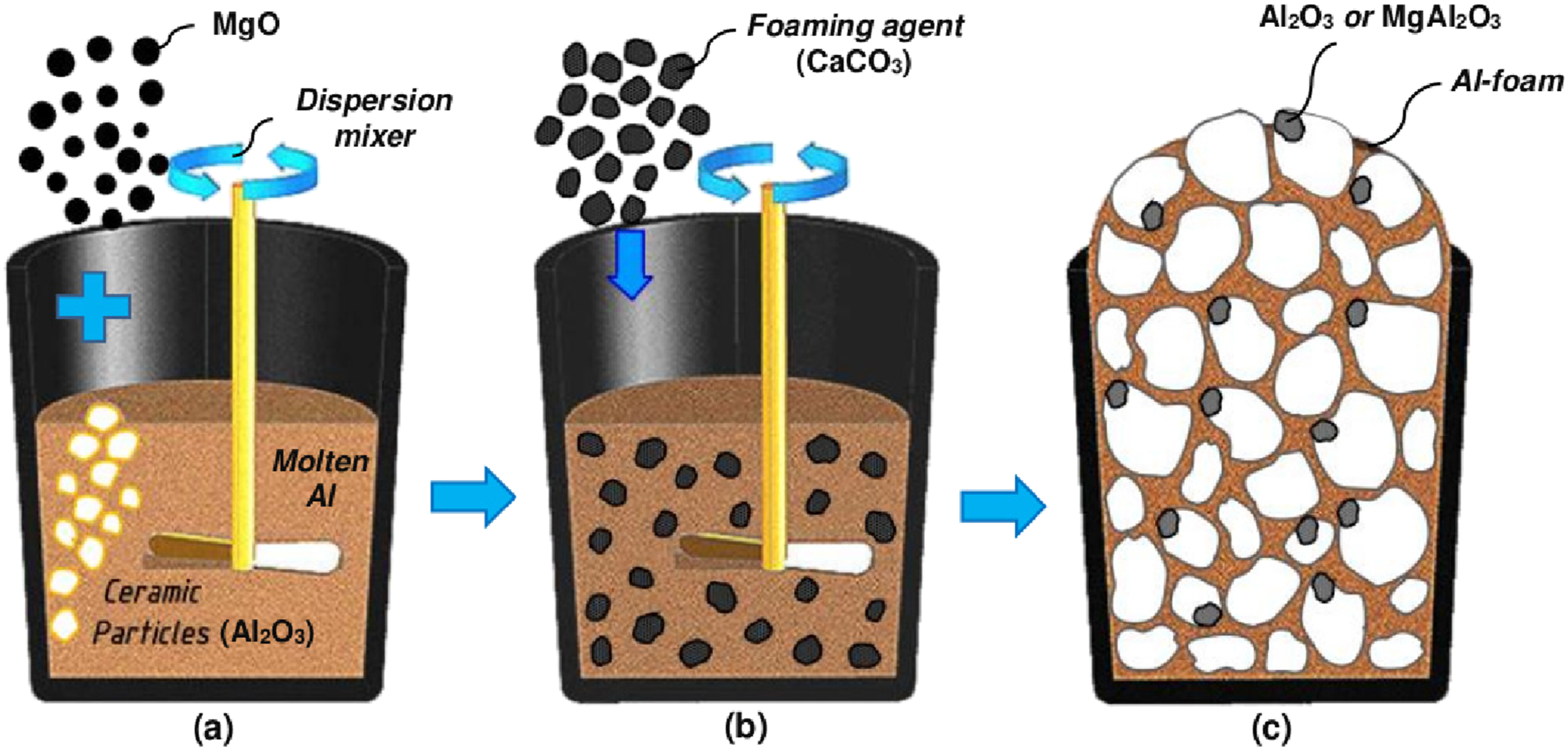
Generally, the stabilizers used are ceramic or oxide (Babcsan, 2003). The stabilizers were used as a particle or powder whose function is to improve the wettability of CaCO3 powder as a foaming agent (Curran and John, 2004) so that it can disperse evenly to all molten aluminum and is able to decompose optimally. In addition, the alumina (Al2O3) powder has a function as a gas bubble stabilizing particle from the decomposition of CaCO3 powder.
Aluminum oxide (Al2O3) is a chemical compound obtained from the refining of aluminum ore (bauxite). Aluminum oxide has a solid form with white color, odorless, and very hygroscopic. In general, aluminum oxide has a crystalline form called corundum. Aluminum oxide or alumina belongs to the group of modern oxide ceramics together with Silica (SiO2), Zirconia (ZrO2), and Barium Titanate (BaTiO2). Aluminum oxide does not react with pure aluminum at temperatures below 1000oC (Babcsan, 2003), so it will form a residual material like in Figure 4(c). Magnesium oxide (MgO) is a hygroscopic white solid mineral that occurs naturally as periclase (MgO). The MgO is stable in the oxide atmosphere to temperatures of 2300°C, and in the reducing atmosphere, it is stable up to 1700°C. In the Al-foam fabrication, MgO will react with alumina to form MgAl2O4, as shown in Figure 4(c) (Vinod kumar et al., 2011; Guo et al., 2015). MgAl2O4 whiskers are expected to be a reinforcement of Al-foam cell walls to increase the strength of Al-foam.
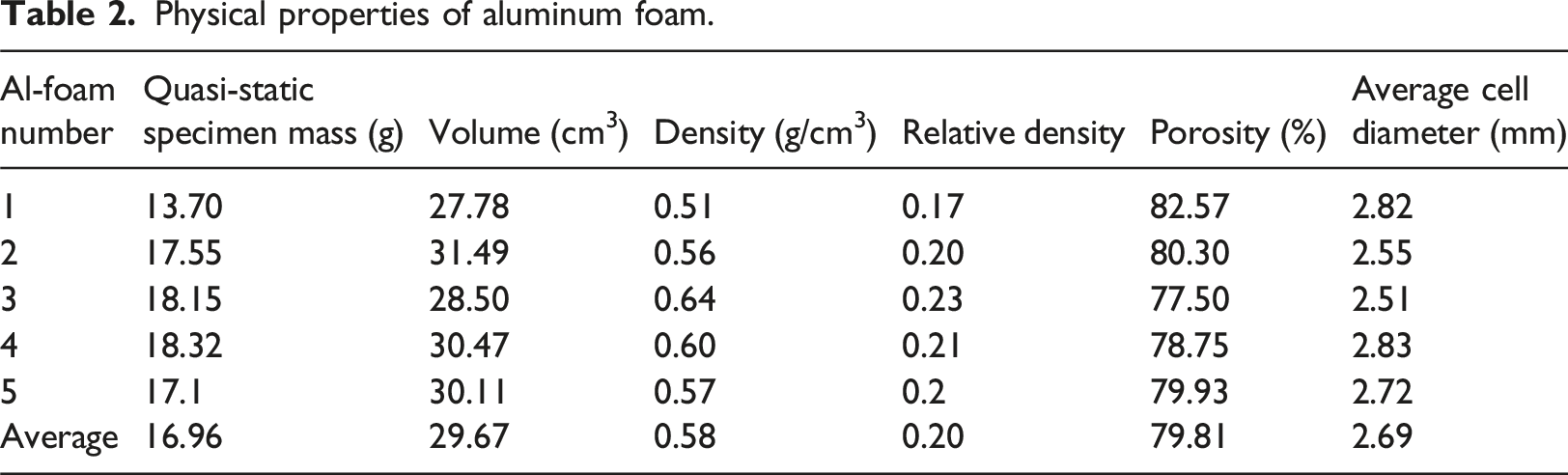
Figure 5 shows typical Al-foam air cavities produced in this research. The distribution of the air cavity appears to be not homogeneous and varies in size. Table 2 shows the physical parameters of each type of Al-foam that has been successfully made. The Al-foam has a density that is almost uniform with an average value of 0.58 g/cm3 (0.51–0.64 g/cm3) or the relative density of about 0.202 (0.17–0.23). The average porosity of the Al-foams was 80% (79.93%–82.57%), with an average cell thickness of 45 μm. The average pore roundness was 85% (100% was a perfect circle) with an average cell diameter of about 2.7 mm, and a pore diameter of 2.51–2.82 mm. Typical aluminum foam cell produced in this study. Physical properties of aluminum foam.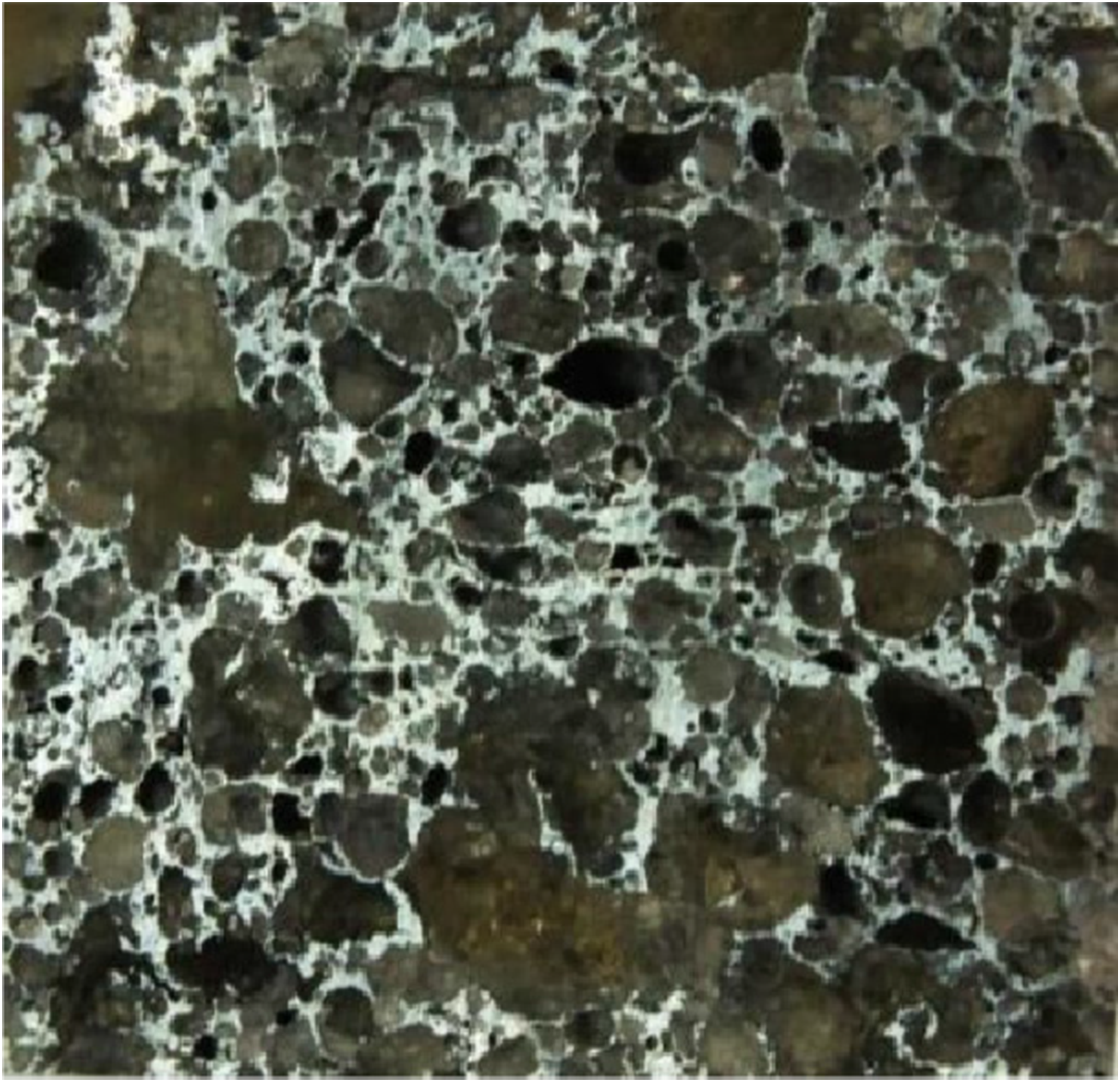
Material characterization of aluminum foam and faceplates
Quasi-static compression test of aluminum foam
The Al-foams were evaluated by a quasi-static compression test to determine the mechanical properties of each type of Al-foam. The test specimen had a cube-shaped with a side length of about 33 mm and an average mass of 16.96 g. The compression test results of these five types of Al-foam are shown in Table 2.
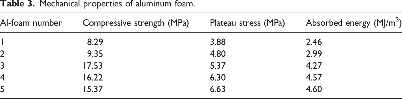
Figure 6(a) shows the loading curve after the compression tests. The Al-foam one and two seem to be the lowest strength, the Al-foam four and five have the largest strength, and the Al-foam three is in the middle. In more detail on the absorbed energy of each Al-foam, Figure 6(b) shows the energy absorption capability during the quasi-static compression tests. Al-foam four and five provide the highest energy absorption capability. With the same relative density, different strengths are obtained for each type of Al-foam. It shows that the stabilizer contributes significantly to the strength of Al-foam. Quasi static compression test of aluminum foams; (a) Loading curve of the Al-foams and (b) Absorbed energy of the Al-foams.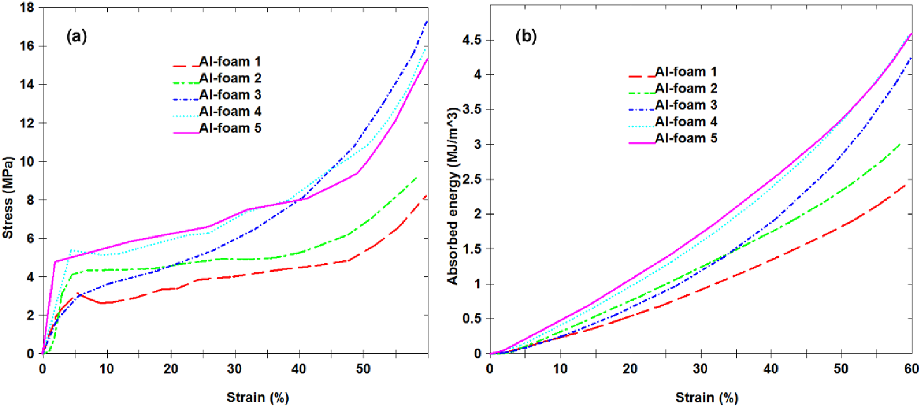
Mechanical properties of aluminum foam.
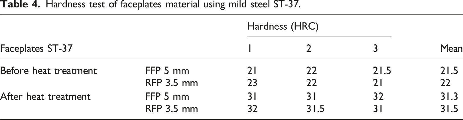
Hardness test for faceplates
Hardness test of faceplates material using mild steel ST-37.
Finite element modeling
LS-DYNA solver, a non-linear dynamic-explicit finite element software, was used in this research. In this section, the finite element reproducible procedures were described in detail, such as initial conditions, contact definitions, bullet modeling, and materials modeling.
Initial conditions and contact definitions
The finite element model for the ballistic test analysis is shown in Figure 7. Boundary conditions consist of sliding support on the FFP edges and a pinned support on the RFP edges. The sliding support stopped the translational movement in the x and y directions, while the translational movement in the z-direction and the rotational movement in the x, y, and z directions were free to move, which was symbolized by (x, y, z, Rx, Ry, Rz) = (1, 1, 0, 0, 0). The pinned support stopped the translational movements in the x, y, and z directions while the rotational movements in the x, y, and z directions were free to move, which was symbolized by (x, y, z, Rx, Ry, Rz) = (1, 1, 1, 0, 0, 0). Boundary and loading condition on finite element model of ballistic analysis.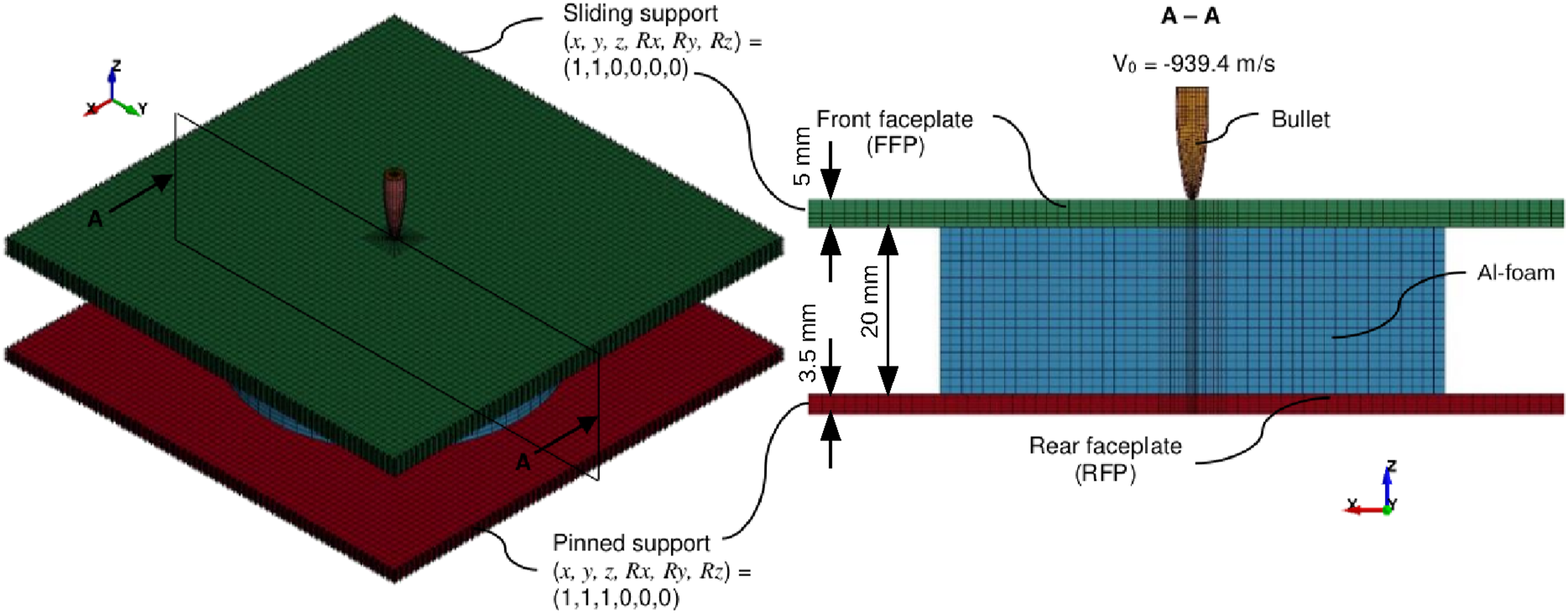
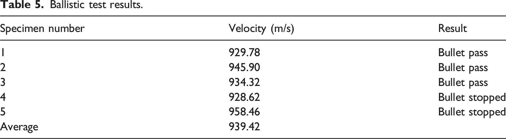
Ballistic test results.
The contact definition among each component in finite element modeling significantly affects the results. In this case, the contact surface-to-surface and eroding surface-to-surface were used. Contact Automatic Surface to Surface was used to define contact between the brass jacket and the lead core. The Contact Eroding Surface to Surface without any soft constraint was used to define contact of the bullet and Al-foam, and the faceplates and Al-foam. The Contact Eroding Surface to Surface with the soft constraint and the segment-based contact options was used to define contact between the bullet and faceplates.
After simulation to validate the experiment was done, additional simulation work was performed to study the Al-foam in a more advanced setup with ceramic layer addition. The added ceramic layer consisted of segmented hexagonal plates where it was expected that the tiny gap between plates would prevent crack propagation. The segmented hexagonal ceramic plates were shown in Figure 8. Boundary and loading condition on finite element model of ballistic analysis.
Bullet modeling
Figure 9 shows the finite element modeling of the bullet. The bullet is a full metal jacket bullet with the core in lead-antimony alloy and the jacket in brass. The bullet geometry for the numerical analysis followed the dimension in Figure 3(a). The bullet has a diameter of 5.7 mm and a height of 20 mm, where the diameter of lead is 4.7 mm, and the brass jacket thickness is 0.5 mm. Both materials were modeled by using the Modified Johnson–Cook material model. The Modified Johnson–Cook material model parameters were adapted from a reference (Peroni et al., 2012), as shown in Table 6. Cockcroft–Latham failure criteria (Cockcroft and Latham, 1968) are used to model the erosion criteria of the bullet elements that are defined as the area under the stress-strain curve of the material. Finite element modeling of the bullet of caliber 5,56 x 45 mm. Johnson–Cook parameters of brass and lead antimony alloy. (Adapted From Peroni et al., 2012).
The density used for the lead–antimony alloy and brass are 11.3 g/cm3 and 8.75 g/cm3, respectively. Melting temperature, heat specific constant, and m for lead–antimony alloy and brass are 525K, 140 J/kg/K, 1 and 1300K, 385 J/kg/K, 1.68 (Johnson and Cook, 1983), respectively. The element type for each component is a solid element with a good quality aspect ratio (less than 10). The element formulation for the aluminum foam is a fully integrated S/R solid intended for elements with poor aspect ratio, efficient formulation. For the FFP, the element formulation of a constant stress solid element (default) is used. For the RFP, brass, and lead, the element formulation of a fully integrated S/R solid is used.
Material modeling
Faceplates
Johnson–Cook parameters for steel ST-37. (Adapted from Pratomo et al., 2020, 2021).
Ceramic
The materials used for faceplates were B4C, SiC, and Al2O3. These materials in their pure form provide extreme hardness that can initiate dwell phenomena with contacting projectile. Three choices of hard ceramic materials were chosen due to their commercial availability where hardness and density are most favorable for B4C and least favorable for Al2O3. Ceramic imposed by high-speed projectile produced elastic-plastic stress wave (Nicholas, 1982) modeled by Hugoniot stress–strain curve obtained from forward/reverse-plate impact testing experiments (Duffy and Ahrens, 1997; Grady, 1995). To perform this computation of ceramic materials suffered by shockwave compression or ballistic impact, researchers commonly use Johnson–Holmquist (JH-2) (Johnson and Holmquist, 1992) material strength and damage models (in LS-DYNA called MAT110).
The strength model consists of the material strength (σ), normalized to Hugoniot Elastic Limit (HEL) strength component when the conditions are intact (σ
i
*
), partially damaged (σ
*
), or fractured (σ
f
*
), which are dictated by the damage parameter, 0 ≤ D ≤1, as shown in equations (1) and (2). As for the normalized intact strength (σ
i
*
), and normalized fracture strength (σ
f
*
), are consisted from intact strength constant (A), intact strength exponent (n), fracture strength constant (B), fracture strength component (m), normalized pressure P
*
=PIP
HEL
, where P is actual pressure and P
HEL
is the pressure at HEL, normalized hydrostatic tensile strength T
*
=TIP
HEL
, where T is maximum tensile hydrostatic pressure of the material, strain rate constant (C), and effective strain rate 


For the damage model, it consists of P
*
, T *, damage parameter, 0 ≤ D ≤1, effective plastic strain, Δε
p
, plastic strain to fracture at a certain pressure P, εpf, damage constant, D
1
, and damage exponent, D2, as shown in equations (5) and (6). From equation (6), it can be understood that at Δεp = 0 at P* = -T *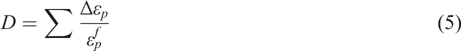


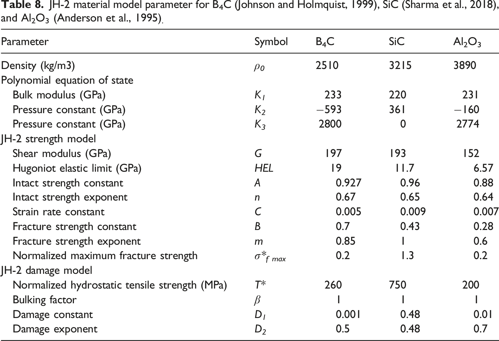
JH-2 material model parameter for B4C (Johnson and Holmquist, 1999), SiC (Sharma et al., 2018), and Al2O3 (Anderson et al., 1995).
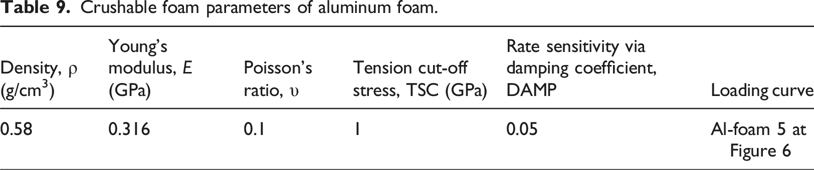
Aluminum foam
Crushable foam parameters of aluminum foam.
Results and discussion
The most critical evaluation was bullet penetration (stop or pass) when going through the AFS, especially the RFP. The RFP integrity is related to the safety of something (human or object) protected by the AFS. In the standard, this test is related to NATO STANAG 4569 level 1, which is an evaluation of the structural resistance to the kinetic energy of 5.56 × 45 mm NATO Ball (SS109) at a shooting range of 30 m and a speed of 910 m/s (NATO, 2012).
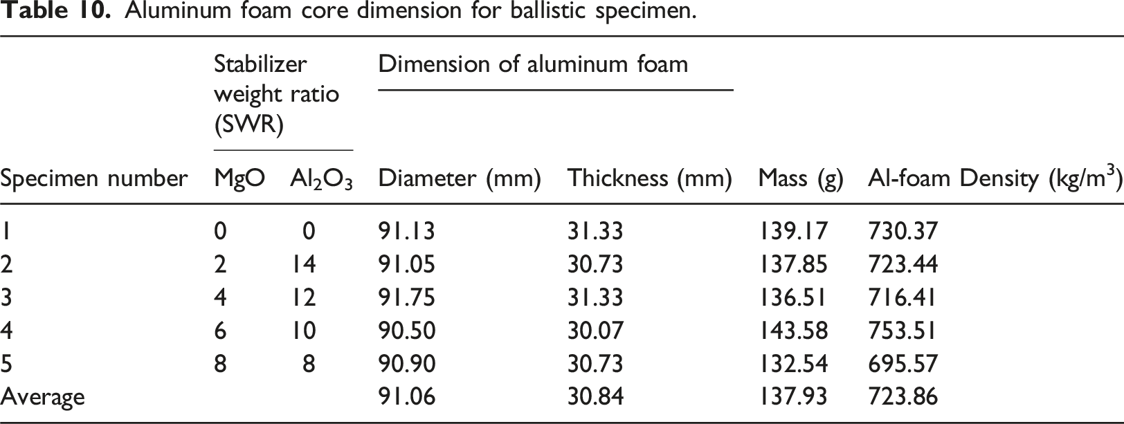
Aluminum foam core dimension for ballistic specimen.
By increasing the mass of MgO in the Al-foam fabrication, it can form more MgAl2O4. Figure 10 shows the indications of MgAl2O4 whiskers on the Al-foam cell wall using a Scanning Electron Microscope (SEM). The presence of massive MgAl2O4 on the Al-foam cell walls makes Al-foam four and five characteristics better than the others. The reaction between MgO and Al2O3 will produce MgAl2O4 that reinforced the aluminum cell walls (Guo et al., 2015). The reaction between molten aluminum with MgO will also produce MgAl2O4 because the molten aluminum will produce Al2O3 due to the reaction between aluminum and air (O2). MgAl2O4 can be produced due to the presence of Al2O3 as the stabilizer or Al2O3 as the aluminum-air product. The function of fiber-like MgAl2O4 on the aluminum matrix is like the function of carbon fiber on a polymer matrix. Morphology of Al2O3 layer and indication of MgAl2O4 at the wall cell of Al-foam number 4 (MgO:Al2O3 = 8:8).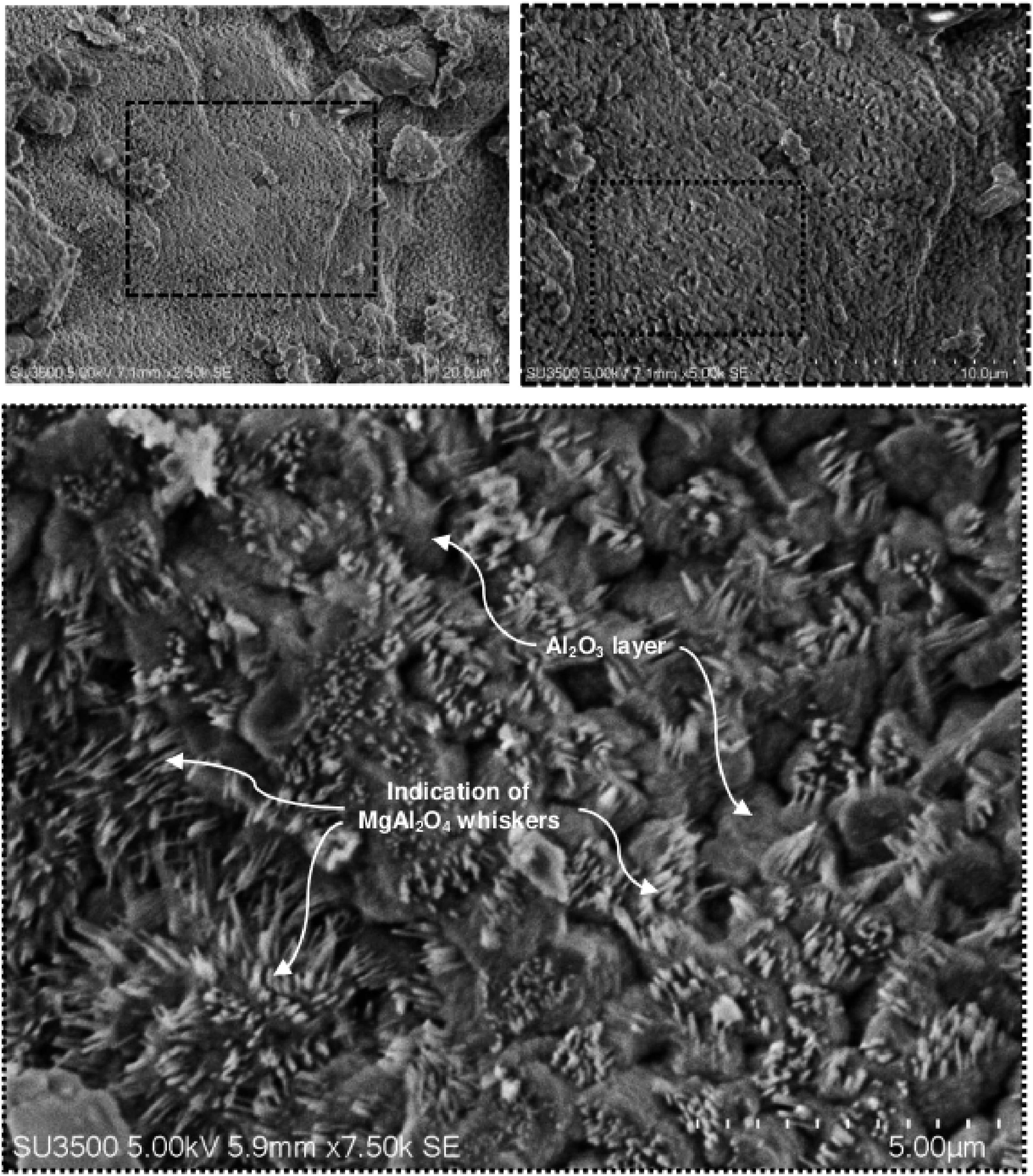
Damage mode of aluminum foam sandwich subjected to ballistic loading.
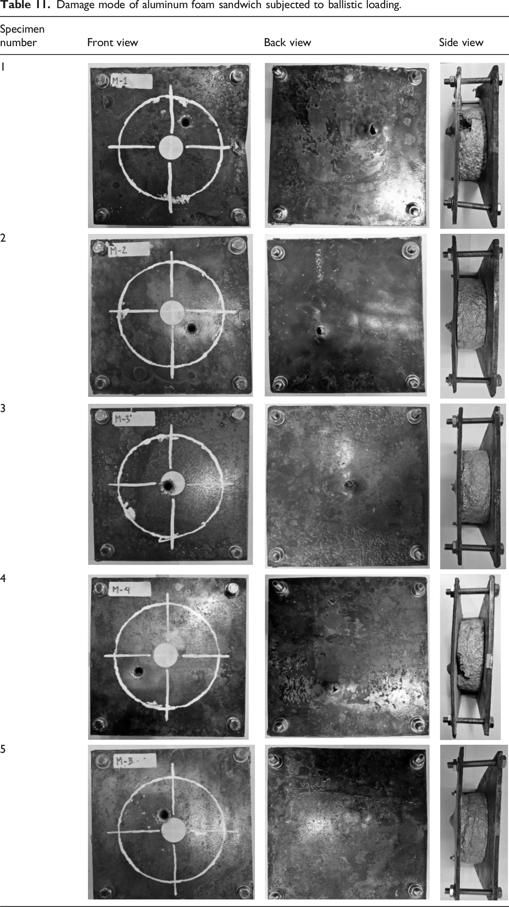
The finite element model was constructed to observe the damage mode and kinetic energy absorption by the AFS. After ballistic testing is reproduced by numerical simulation, the bullet penetration can be traced inside the AFS, as shown in Figure 11. During 0–0.025 ms, the high-speed bullet successfully perforates the front faceplate (FFP). At 0.035 ms, the bullet mass is now only 30% of the initial mass because it experiences a massive erosion. At the finite element modeling, the erosion in the bullet and the faceplates are represented by the eroded element that is defined using the Cockcroft–Latham criterion (see Table 6 and Table 7). With about 30% of the bullet’s mass remaining, it can easily perforate the Al-foam plate (0.045–0.065 ms). Finally, the movement of the bullet was stopped by the rear faceplate (RFP) at 0.085 ms, and it left only a very small piece of the bullet. It has a good agreement with the experiment number five in Table 5, which stop the bullet penetration on the rear plate (RFP). Bullet penetration inside the specimen of aluminum foam sandwich.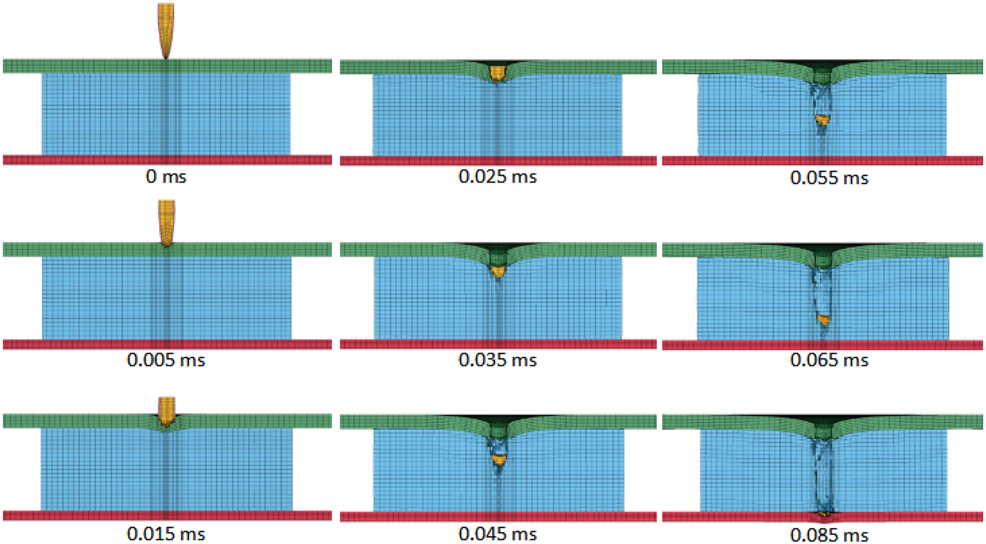
The damage mode comparison results between simulation and testing give an excellent agreement, as shown in Figure 12(a)–(b), so that the simulation in this study has high fidelity. This simulation also obtains the energy absorption of each component of the AFS, as shown in Figure 13. The FFP, RFP, and Al-foam absorb the bullet kinetic energy, respectively, 291.2 kJ (44.9%), 80.0 kJ (12.4%), and 30.4 kJ (4.7%), respectively (see Figure 13). The bullet (brass and lead) also absorbed the kinetic energy of about 104.3 kJ (16.1%) and 142.6 kJ (21.9%), respectively. The heat-treated ST-37 plates (FFP and RFP) absorb most of the bullet kinetic energy (57.3%). The hardened surfaces erode the bullet body drastically. The high ductility inside thickness makes the bullet difficult to break through so that it effectively absorbs the energy. Meanwhile, Al-foam absorbs no more than 5% of the kinetic energy. This is because the small cross-section of the bullet that makes only a small portion of the Al-foam used to absorb impact energy, while the rest majority portion of the Al-foam cross-section is not used at all to absorb bullet kinetic energy. The contribution of Al-foam will be maximized with the existence of ceramics layer so that more Al-foam cross-section experience compression (see Figure 14). Comparison of the damage mode of aluminum foam sandwich subjected to ballistic test: (a) Simulation and (b) Test. Energy absorption per component of the aluminum foam sandwich. Comparison of bullet penetration inside the CAFS armor with additional Al2O3, SiC, and B4C layer (at 0.2 milliseconds).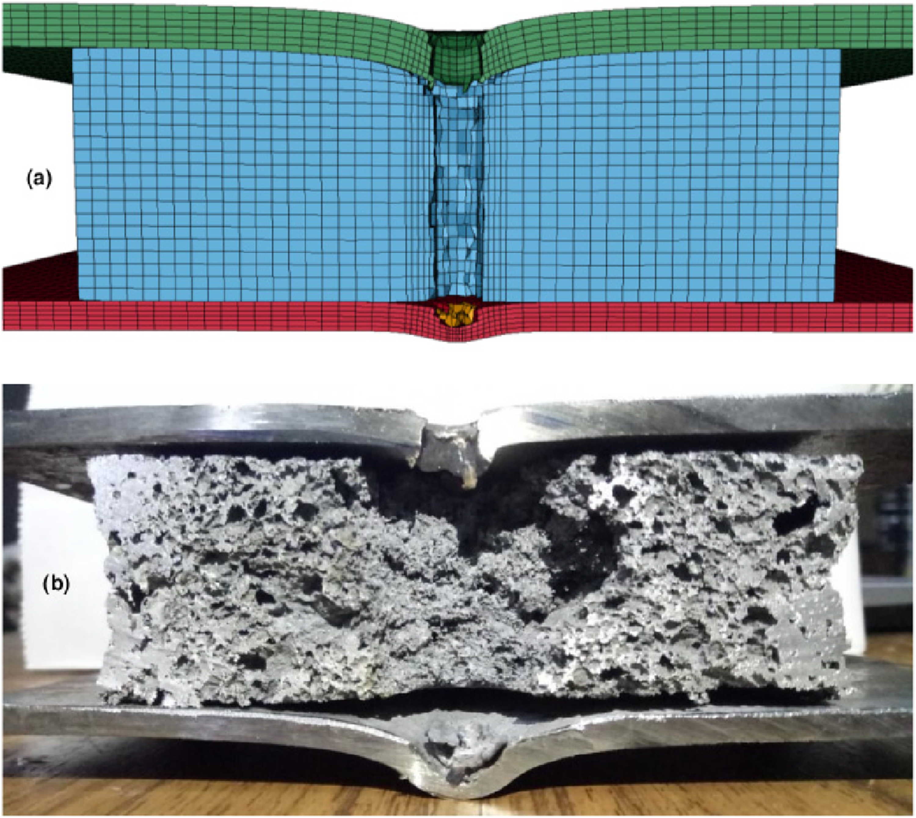
Figure 15 shows global statistics of energy balance during the simulation. This curve can be used to validate the reliability of the numerical simulation by looking at total energy that is relatively constant and sliding energy that is still within a reasonable range and not negative values. The total kinetic energy of the bullet is 1654.6 kJ, where the bullet mass is 3.75 g, and the bullet velocity is 939.4 m/s. Internal energy, an indication of absorbed energy, is only about 648.9 kJ or about 40% from the kinetic energy, the remaining 60% of the kinetic energy in the simulation is lost due to the eroded elements (eroded kinetic and internal energies). In real physics, it can be described as the change of kinetic energy into heat energy which causes the material to melt due to high-speed friction. Global statistic of energy balance in the ballistic simulation of aluminum foam sandwich.
Absorbed energy of each component of the CAFS constructions armor subjected to ballistic loading.
Table 12 shows the summary of the absorbed energy during ballistic impact. The absorbed energy is distributed for each component such as front faceplate (FFP), Al-foam, bullet, rear faceplate (RFP), and ceramic. FFP has the highest percentage of absorbed energy that is the same phenomenon in the previous simulation in AFS (in Figure 13). The interesting phenomenon appeared in the Al-foam, the absorbed energy in Al-foam consistently increases from Al2O3, SiC, to B4C that are 8.5, 13.86, and 14.88 kJ, respectively. This is phenomenon due to the high correlation between absorbed energy Al-foam and shear modulus of the ceramic (Peason’s correlation r = 0.998, p < .05). The shear modulus for Al2O3, SiC, to B4C are 152, 193, and 197, respectively, as also shown in Table 8.
Shear modulus describes a resistance of materials subjected to shear forces. Ballistic loading is dominated by the extreme shear forces of the bullet. Ballistic protectors using homogeneous materials rely heavily on energy absorption through shear deformation which is well-known. The phenomenon of increasing energy absorption of Al-foam with the increasing shear modulus of ceramic creates new insight into the synergistic performance between hard materials and softer materials for ballistic impact protection applications.
It is generally known that Al-foam when subjected to extreme shear forces such as ballistic impact, will result in small portion energy absorption whereas the maximum energy absorption from Al-foam is compressive loading (Brekken et al., 2022). With the combination of ceramic and Al-foam, another energy absorption mechanism from the compressive direction appears, which maximizes the usage of Al-foam in absorbing impact energy.
This high correlation between absorbed energy by Al-foams and shear modulus of ceramics can be explained by Figure 14. It is clearly shown in Figure 14 that the B4C and SiC ceramics compressed the Al-foam denser than Al2O3. It is also clear that the ceramic insertion into the armor can significantly stop the incoming projectile before it penetrates the beneath components. These ceramics also can optimize the absorbed energy by Al-foam.
Brittle failure of any ceramic is not able to be avoided due to the concentrated and high-speed shear load of the bullet. This crack does not spread to the adjacent ceramic due to the discontinuous hexagon construction. This is more effective in withstanding subsequent bullet impacts in different positions compared with continuous ceramic plate construction. In continuous ceramic plates, crack propagation spreads and weakens the entire structure. However, regarding the combination with aluminum foam, non-continuous plate construction needs to be studied according to the most effective thickness and area. Continuum ceramic plates combined with Al-foam may also be an interesting future research material.
Conclusion
The experimental validation and numerical study on ballistic resistance of sandwich structure with generated MgAl2O4 whiskers on aluminum foam (Al-foam) core fabrication was conducted. Five types of Al-foam have been successfully made and characterized. In the mechanical properties, the Al-foam with the stabilizer weight ratio of MgO & Al2O3 was 6:10 and 8:8 gave the highest value on the plateau stress and the energy absorption capabilities. This strength was in line with the ballistic resistance of the aluminum foam sandwiches (AFSs). From the ballistic test, it was found that the AFS with these two cores can only successfully stop the bullet penetration. From SEM, there are indications of MgAl2O4 on the Al-foam cell walls, which can increase the Al-foam mechanical properties. In the numerical results, the damage mode showed an excellent agreement with the experimental results, while the contribution on the energy absorption capability for the front faceplate (FFP), rear faceplate (RFP), and Al-foam were 44.9%, 12.4%, and 4.7%, respectively. Energy absorption was dominated by faceplates due to surface hardness and high ductility. Adding ceramic layer above the Al-foam is a good idea that showed a dwell or erosion phenomena leading to interface defeat of projectile before it reached Al-foam. During impact with ceramic, Al-foam is compressed so that it can absorb more energy. It was found that ceramic with higher shear modulus tend to allow the Al-foam to absorb energy more upon impact.
Footnotes
Acknowledgements
The authors would like to thank LPPM UNJANI and LPPM Unhan RI for their funding support. We also would like to thank PUSDIK KOPASUS for providing ballistic test facilities. Thanks are due to LSTC for the courtesy of the academic license of LS-DYNA to Lightweight Structure Research Group ITB.
Declaration of conflicting interests
The author(s) declared no potential conflicts of interest with respect to the research, authorship, and/or publication of this article.
Funding
The author(s) disclosed receipt of the following financial support for the research, authorship, and/or publication of this article: This work was supported by the LPPM Unjani dan LPPM Unhan RI.