
Abstract
The metal-intermetallic laminate composite Ti/Al3Ti can be used as protective armor in aerospace and military applications, due to its low density, high strength, and superior impact-resistant performance. The ballistic performance of the laminate composite was studied by ballistic testing and finite element technology. The failure modes, such as radical cracks, layer delamination, and plastic deformation, have been found after the ballistic test, and the specific energy absorption was used to evaluate the ballistic capacity of the material. The finite element model of the Ti/Al3Ti impacted by the projectile was established by considering the interface, which was simulated by the solid elements with zero thickness. The simulation results demonstrate the failure process of the interface during penetration. The interfacial failure allowed for layer detachment with its labor layers. The simulation results agree well with that of the experiment, and the practicality and credibility of the model is verified.
Introduction
The Ti/Al3Ti metal/intermetallic laminate (MIL) composite is a new armor material, which combines the toughness of metal with the high specific stiffness, strength, and creep resistance of the intermetallic components. 1 –4 The laminate structure and damage mode allowed for higher impact energy of the Ti/Al3Ti composite than other materials. The ballistic performance of the composite has been studied experimentally by Harach, who found that the protective properties are similar to armor steel. 5 Fan et al. simulated the ballistic test by two-dimensional (2D) finite element programming to obtain the stress responses and damage evolution, and the failure and energy-absorbing mechanisms of the Ti/Al3Ti composite were analyzed on the simulation results. 6 Many researchers have also studied the damage process of Ti/Al3Ti by simulation technology. The strength model, damage, and failure model of Ti/Al3Ti composite were established by Zelepugin and Shpakov, and in this model, the material strength was highly affected by temperature and failure degree. 7 The established model was used to simulate the process of tungsten alloy projectile penetration through the composite, and the simulation results indicate that the Ti/Al3Ti has a better ballistic performance than titanium alloy and intermetallic Al3Ti. 8 The material model of the Al3Ti matrix was developed on the basis of the Johnson–Holmquist-Ceramics (JH-2) constitutive model in our previous study, which can be used to simulate the mechanical responses of the Ti/Al3Ti matrix. 9,10 In the above research, the interface between the Ti and Al3Ti layers was ignored. The interface plays an important role in the protective mechanism, and the interfacial damage affects the complete failure process of the material.
In this article, the ballistic performance of the Ti/Al3Ti MIL composite was investigated by ballistic impact testing. The penetrating process has been simulated by ANSYS/LS-DYNA 14.0 software considering the interfacial element. The damage evolution and dynamic responses of the composite were studied, and the protective capacity was evaluated using the specific energy absorption (SEA) parameter.
Experiment and numerical model
Material preparation
The foils of Ti and Al are stacked alternately in a vacuum hot-pressing furnace to prepare the Ti/Al3Ti laminate composite. The temperature and pressure are controlled to ensure the final product only contained Ti and newly generated Al3Ti. 11 The microstructure of the Ti/Al3Ti laminate composite is shown in Figure 1.

The microstructure of the Ti/Al3Ti.
Experimental setup
The target material is Ti/Al3Ti with dimensions of 85 × 75 × 7 mm3. The target has 17 layers containing 9 layers of Ti and 8 layers of Al3Ti. The experimental configuration of the ballistic test is shown in Figure 2, which includes a ballistic gun, a speed measuring box, a high-speed camera, and a target box. The initial and residual velocities of the ballistic are captured by the speed measuring box and high-speed camera, respectively. The core of the armor-piercing bullet is composed of alloy steel.

Experimental configuration of the ballistic test.
The common evaluation methods of protective performance for materials are the ballistic limit speed (V 50) method and SEA method. For the same materials, the V 50 is not a constant value when the thickness of the material changes, and, as a result, SEA is employed to evaluate the protective properties of the materials. The SEA is defined as the ratio of the absorbed energy to the area density of the target material. Neglecting the deformation of the projectile, the SEA can be calculated by the following equation
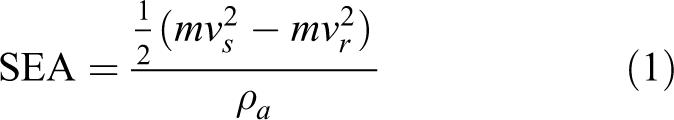
where m is the mass of the projectile, Vs
and Vr
are the initial and residual velocities of the projectile, respectively, and
Numerical model
To understand the damage evolution of Ti/Al3Ti, a ballistic test was simulated by ANSYS LS-DYNA finite element software. The geometry, size, and initial conditions were maintained between the experimental and simulated ballistic tests. The dynamic response of the Ti reinforcement and Al3Ti matrix were calculated by Johnson–Cook 12 and JH-2 13 constitutive equations, respectively. The material parameters are derived from the literature, 10,12 which are given in Tables 1 and 2. The meaning of the letters can be found from the LS-DYNA user’s manual. 14
Parameters of Ti in JC constitutive model.
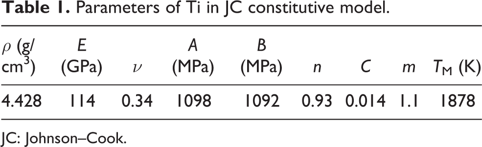
JC: Johnson–Cook.
Parameters of Al3Ti in JH-2 constitutive model.

JH-2: Johnson–Holmquist ceramics.
From the research of Zhou et al., 15 the thickness of the interface is 1.2 µm. The simulation model will have large quantities of elements if meshed with conventional 3D elements to insure its uniformity. Too dense elements will seriously affect the calculation speed. Although the plan element can solve the issue, it is incapable to simulate the interaction between layers with its four nodes. The elements types in the simulation here are 3D elements. For the interface, the elements with zero thickness are used. These elements look like plan elements, but they are effectively 3D, which have been proceeded by node coincidence. The diagram of the interfacial element is shown in Figure 3. In the preprocess of the finite element calculation, the upper nodes of the interfacial element in the thickness orientation, such as nodes 1 and 3, are moved until the nodes coincide with the lower nodes 2 and 4. After this treatment, the number of elements can be efficiently reduced; meanwhile, the real connection relationship between the layers of Ti and Al3Ti is simulated. The cohesive elastic model was used to calculate the mechanical response of the interface. The failure of the element was judged by the tensile strength. The values of the parameters of the cohesive elastic model for interface are taken from the literature, 15,16 and listed in Table 3, in which ρ is the mass density, E T is the stiffness in the plane of the cohesive element, E N is the stiffness normal to the plane of the cohesive element, and F N is the force in the normal direction for tensile failure. The projectile deformation is negligible, so the rigid model was employed for the projectile.
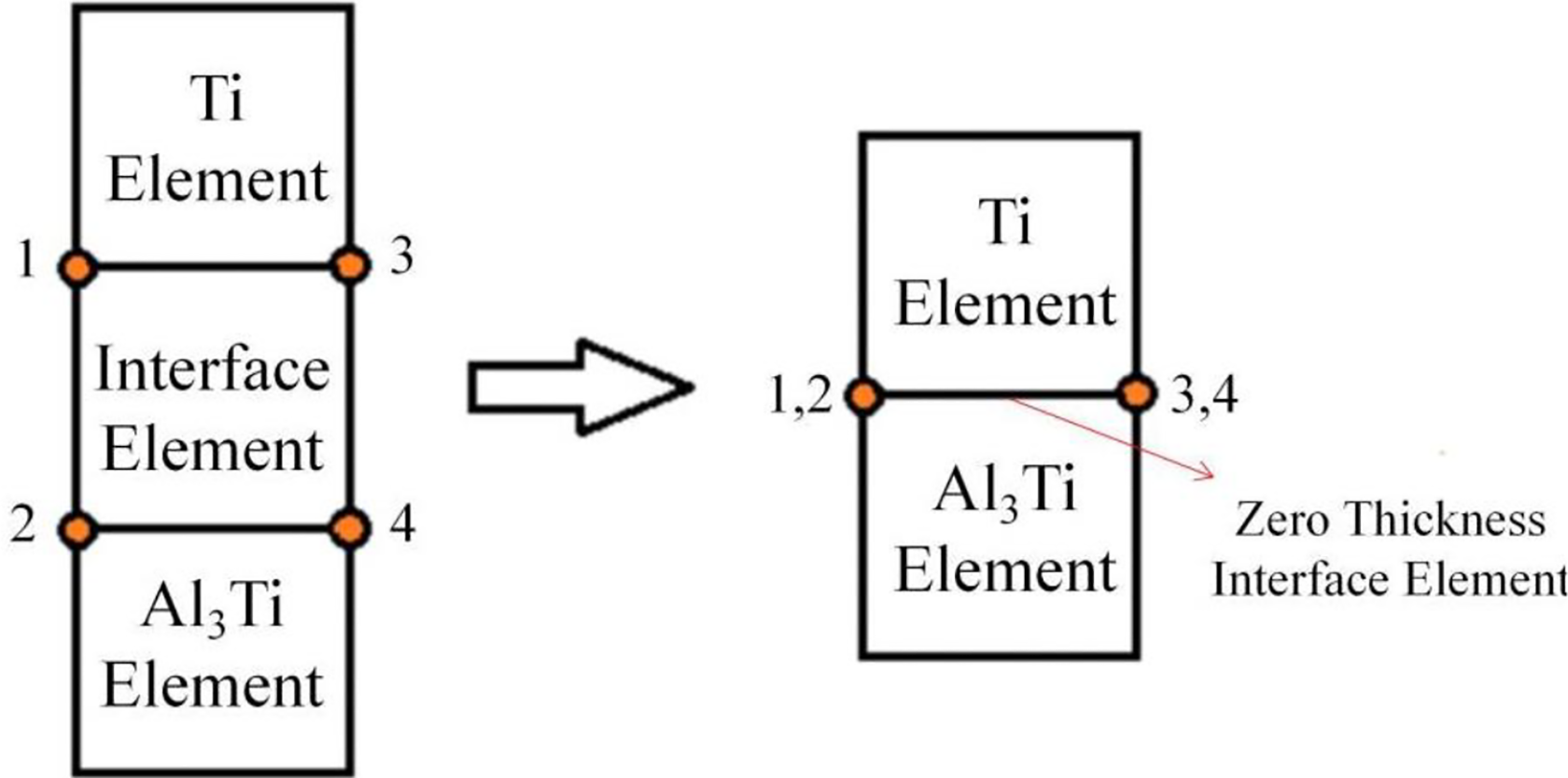
Generation of interfacial elements with zero thickness.
Parameters of the interface in cohesive elastic model.

Results and discussion
Results and analysis of the ballistic test
The failure morphology of the target material is shown in Figure 4. In the front of the target, there are similar radial cracks around the penetrated hole. When the projectile reaches the surface of the target, an intense compression wave was produced, which crushed the Al3Ti. Then the stress wave rapidly propagated to the back of the target, and the wave was reflected at the interface. The reflected wave in the matrix layer became a tensile wave due to the higher mechanical impedance of the Al3Ti compared to the Ti. Under the action of the tensile stress, many cracks were generated in the Al3Ti because of its low tensile strength. As shown in the second image of Figure 4, a piece of Ti was peeled off by the tensile stress, which can be seen from the multiple cracks propagated from the penetration hole to the material edge. In addition, when the tensile stress was higher than the cohesive strength of the layer, delamination occurred at the interface. The projectile velocity decreased as the penetration depth increased, and the plastic deformation of the target composite was more obvious at early penetration stages. The plastic deformation caused the material at the back of the target to produce plugging failure and petal-like deformation.

Failure morphologies of the Ti/Al3Ti MIL composite after the impact tests. MIL: metal/intermetallic laminate.
The initial velocity of the projectile was measured by the speed measuring box as 802.6 m/s. The residual velocity captured by the high-speed camera was 711.8 m/s. Then the SEA value was calculated by equation (1). Table 1 shows the area density and SEA of Ti/Al3Ti and other common armor materials. 17 The SEA of the Ti/Al3Ti is higher than the fiber/ceramic composite given in Table 4, but the area density of the Ti/Al3Ti is relatively low. It is shown that the protective properties of Ti/Al3Ti are excellent.
Protective performance comparison of different armor materials.

SEA: specific energy absorption; MIL: metal/intermetallic laminate.
Finite element method analysis
The penetration process of the projectile impacting Ti/Al3Ti laminate composite is shown in Figure 5. No plastic deformation has been found at the early penetration stages. As the penetrating depth increases, the materials deform at the back of the target. At 21 µs, a fragment was produced by the punching shear fracture on the front of the projectile. Finally, petal-like deformation occurs at the front and back of the target, and the damage at the back surface is more intense than the front.
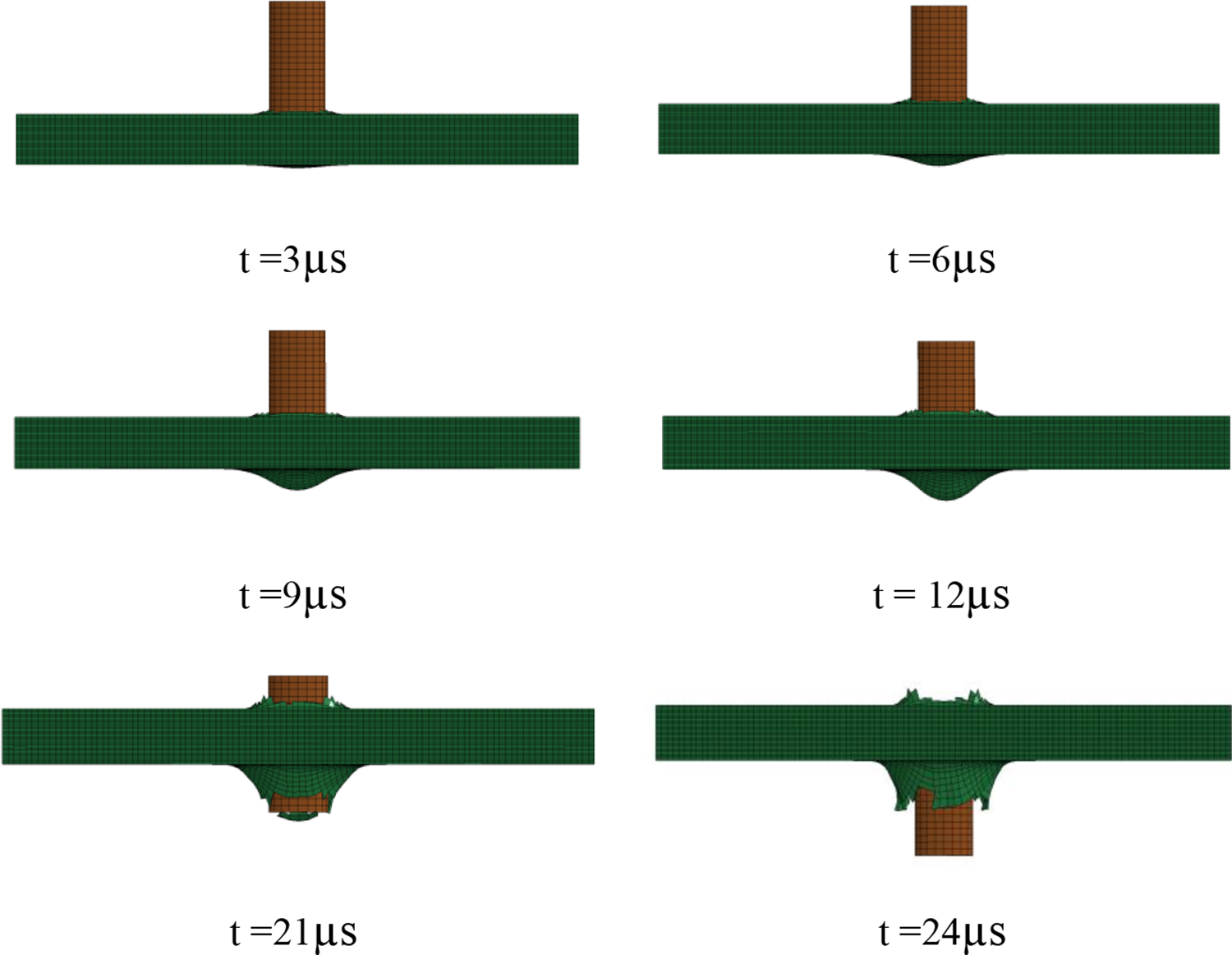
Penetration depths at different times, as simulated by FEM.
Many studies have investigated the damage of the Ti and Al3Ti layers, but few have investigated the interface, which is the emphasis of this simulation. The interfacial element will be removed once the stress reaches the setting tensile strength. The damage morphology of the first and last interface during the simulation is given in Figure 6. The damage begins at the penetrating hole at the first interface. The velocity of the stress wave is faster than the projectile, so the material at the last interface at the front of the projectile becomes damaged when the stress wave transmits to the last layer, even if the projectile has not reached the interface. At the early stages of damage, the damaged area of the interface has a circular shape. Along with the penetration, the shape is changed to the form of a cross. From the simulation results, the damage degree of the last layer is more severe than the first interface. The interfacial damage can cause delamination of the Ti and Al3Ti layer, as shown in Figure 3. The material damage of the last interface at the four corners is less, which means that the last Ti layer at this location combines well with the upper materials, which coincide with the experimental results.

Damage evolution process of the interfaces: (a) the first interface and (b) the last interface.
The initial velocity in the simulation is 802.6 m/s, which is similar to the ballistic test. The residual velocity calculated by simulation is 717 m/s, which is slightly higher than the experimental results. In contrast, the finite element model ignoring the interface has also been established. In the model, the layers are connected by the same node and cannot simulate the interfacial delamination. When ignoring the interfacial damage, the residual velocity is 706 m/s, which has overestimated the protective capacity of the Ti/Al3Ti laminate composite. This is because the composite interface is designed as a weakly bonded interface. Once the interface is damaged, the energy cannot be transmitted between layers, and the protective capacity is decreased.
Conclusion
The protective performance of the Ti/Al3Ti laminate composite was evaluated by experimental and numerically simulated methods. The ballistic test shows that radical cracks, layer delamination, plastic deformation, and plugging shear fracture occur when the composite is impacted by a projectile. Moreover, the degree of damage at the back of the target material is more serious than the front. The SEA of the Ti/Al3Ti is 21.59 J·m2/kg, which is higher than many fiber/ceramic composites. The test was then reproduced by finite element simulation by considering the interfacial damage. The interface was modeled by elements with zero thickness, and the failure of the interface was assessed using tensile strength criteria. The damage shape of the interface changes from a circle to a cross throughout the process. Compared with the model ignoring the interface, it was found that the model including the interface has obtained a lower residual velocity, which demonstrated that it overestimated the protective capacity of the Ti/Al3Ti composite.
Footnotes
Declaration of conflicting interests
The authors declared no potential conflicts of interest with respect to the research, authorship, and/or publication of this article.
Funding
The authors disclosed receipt of the following financial support for the research, authorship, and/or publication of this article: This work was financially supported by the National Natural Science Foundation of China (no. 11602230), the Young Talent Promotion Project of Henan Province (no. 2019HYTP002), the Science and Technology Research Project of Henan Province (no. 202102210089 and 202102210274), and the Program for Innovative Research Team in Science and Technology in the University of Henan Province (no. 20IRTSTHN015).