
Abstract
This paper investigates the effect of material extruded body armour specimen size on stab penetration depth and back-face signature (BFS) and establishes the minimum thickness required for a series of material extrusion materials to provide protection against the UK Home Office Scientific Development Branch (HOSDB) body armour KR1-E1 requirements. In stage one, material extruded planar test specimens ranging from 40 × 40 mm to 80 × 80 mm in length and width with 10 mm increments at three different thicknesses, 6, 8 and 10 mm, were stab tested under 24 joules of impact energy using a gravity driven drop test apparatus. In stage two, 50 × 50 mm specimens in six material categories, PC, ABS, PLA, TPLA, PA and TPU, were manufactured at different thicknesses via material extrusion and impacted in accordance with the UK HOSDB KR1-E1 stab impact energy level as they were the optimum size when considering overall stab and BFS performance. The study established the fundamental steps towards the use of material extrusion in future personal protection solutions. Results demonstrated that stab penetration and BFS were dependent on specimen size, thickness and material type, and there was an inverse relationship between stab penetration depth and BFS. Also, a minimum thickness of 5 mm for PC and TPLA, 6 mm for ABS, 7 mm for PLA, 11 mm for PA and 12 mm for TPU, with 100% print density, was required in order to provide protection against the HOSDB KR1-E1 level of 24 J stab impact energy.
Keywords
Introduction
Throughout history, body armour has been an important protective solution in increasing wearer survivability in life-threatening situations such as stabbing and slashing incidents (Ashdown, 1909; Horsfall, 2000). While historical armour included wood breastplates, treated animal hides, metal riveted plates or chain-mails (Laible and Barron, 1980; Nayak et al., 2018), advancements in material science have led modern armours to be manufactured from engineering grade materials in the form of rigid materials such as metals (Ben-Dor et al., 2012; Paman et al., 2020), polymers (Benzait and Trabzon, 2018; Nayak et al., 2018; Weerasinghe et al., 2020) and ceramics (Pinto et al., 2012; Serjouei et al., 2015), as well as more flexible materials in the form of aramid fibres like Kevlar® and Twaron® (Majumdar et al., 2013; Nilakantan, 2018; Yadav et al., 2016; Yang et al., 2015) and shear thickening fluids (Weerasinghe et al., 2020; Zhang et al., 2022). Such modern solutions have advanced the protective performance offered by stab resistant body armours (SRBA); however, historical issues, such as health problems due to the ill-fitting of armours, poor thermal and moisture management, as well as their often restrictive and cumbersome nature, continue to exist even with modern SRBA (Arciszewski and Cornell, 2006; Dempsey et al., 2013, 2014; Majumdar et al., 1997).
Additive manufacturing (AM) technology, commonly known as 3D printing, is increasingly being used in a range of novel applications across a number of high performance fields including, but not exclusive to, aerospace (Blakey-Milner et al., 2021), electronics (McGhee et al., 2018) and health rehabilitation (Paterson et al., 2015). The high degree of design freedom and uniformity nature of AM has also enabled researchers to manufacture additively manufactured wearables (Bingham et al., 2007) and protective structures (Johnson et al., 2013; Ngo et al., 2018) that meet a range of varying product performance requirements.
The utilisation of AM technologies over conventional processes for the manufacture of protective structures such as body armour has also been demonstrated across a range of AM processes including laminated object manufacturing (LOM), laser sintering (LS) and material extrusion (ME) due to advantages including but not limited to: • the ability to utilise digital design and manufacturing technologies with a view to providing personalised fit and protection levels within a single structure, which may be difficult or impossible to achieve using conventional techniques. • the opportunity to develop hybrid additive-textile armours with a view to further drive innovation in the development of protective structures. • establishing a potentially more sustainable and environmentally friendly fabrication process due to the additive nature of 3D printing technologies such as material extrusion. • further minimising the need for multiple manufacturing processes, therefore, optimising resources and minimising lead times.
Ceramic monolithic flat and curved layered body armours manufactured via LOM were developed by Klostermann et al. (1999). Additively manufactured stab resistant single-layer planar specimens from Duraform and Duraform EX (Johnson et al., 2018a), dual-layered planar specimens from DuraForm EX (Johnson et al., 2015), planar and articulated scale-like specimens from PA 2200 (Johnson et al., 2013) and bio-inspired articulated specimens from DuraForm EX (Johnson et al., 2018b), have also previously been manufactured through the use of LS and stab tested following the UK Home Office Scientific Development Branch (HOSDB) body armour standard. Laser sintered multi-layered planar specimens made up of PA 3200, PA 4300 and PA/GF and pyramid structured plates from PA 3200 have also been evaluated using finite element analysis (FEA) and validated in terms of their stab resistance (Gong et al., 2019). In their study, He et al. (2018) manufactured egg-shelled structures with varying dimensions via LS from PA 3200, stab tested the specimens and assessed the effect of printing orientation (He et al., 2018). Single and dual-layered planar and pyramid-like samples made up of PA 3200 material have also been evaluated in terms of their stab protective performance (Jiang et al., 2016, 2017), as well as the effect of samples manufactured via LS using carbon fibre polyamide (Yuan et al., 2017b).
In all, there is much published literature regarding the use of LS for the development of SRBA, with little published on the performance of materials used in ME. Examples of such works include estimating the stab performance of specimens manufactured from ABS and PC-ABS by FEA, and validating through a range of stab tests (Maidin et al., 2019; Maidin and Seeying, 2015). In addition, Ahrendt et al. (2019) evaluated material extruded aramid fibre-reinforced test specimens at different thicknesses in terms of their stab resistance (Ahrendt et al., 2019). Moreover, there are still many areas left unexplored when evaluating the suitability of ME for SRBA. For example, little is known on the effect of specimen size on stab penetration depth and the back-face signature (BFS) – which is the deformation on the backside of a piece of armour on the body after an impact, of such materials yet.
Consequently, the aim of this research is to understand the effect of the size of SRBA specimens manufactured via ME on stab protective performance and BFS as well as determine the minimum thickness required for a selection of commonly used and accessible ME materials which is capable of providing stab protection within the UK HOSDB body armour standard for protection level KR1-E1.
Experimental methodology
Stage one: geometry characterisation
Test specimen materials, geometry and design
Two common ME materials were identified for the manufacture of a series of test specimens: Ultimaker’s Acrylonitrile Butadiene Btyrene (ABS) and Polylactic Acid (PLA), due to their printability and availability in the market (Rodríguez-Panes et al., 2018). Specimens were square and planar in shape across five different sizes ranging from 40 × 40 mm to 80 × 80 mm in length and width, increasing in 10 mm increments, across three different thicknesses: 6, 8 and 10 mm. The design of all test specimens, as illustrated in Figure 1, was completed within the solid modelling computer aided design (CAD) software SolidWorks® (version 2018, Dassault Systemes, Waltham, MA, USA). Schematic of the specimen design.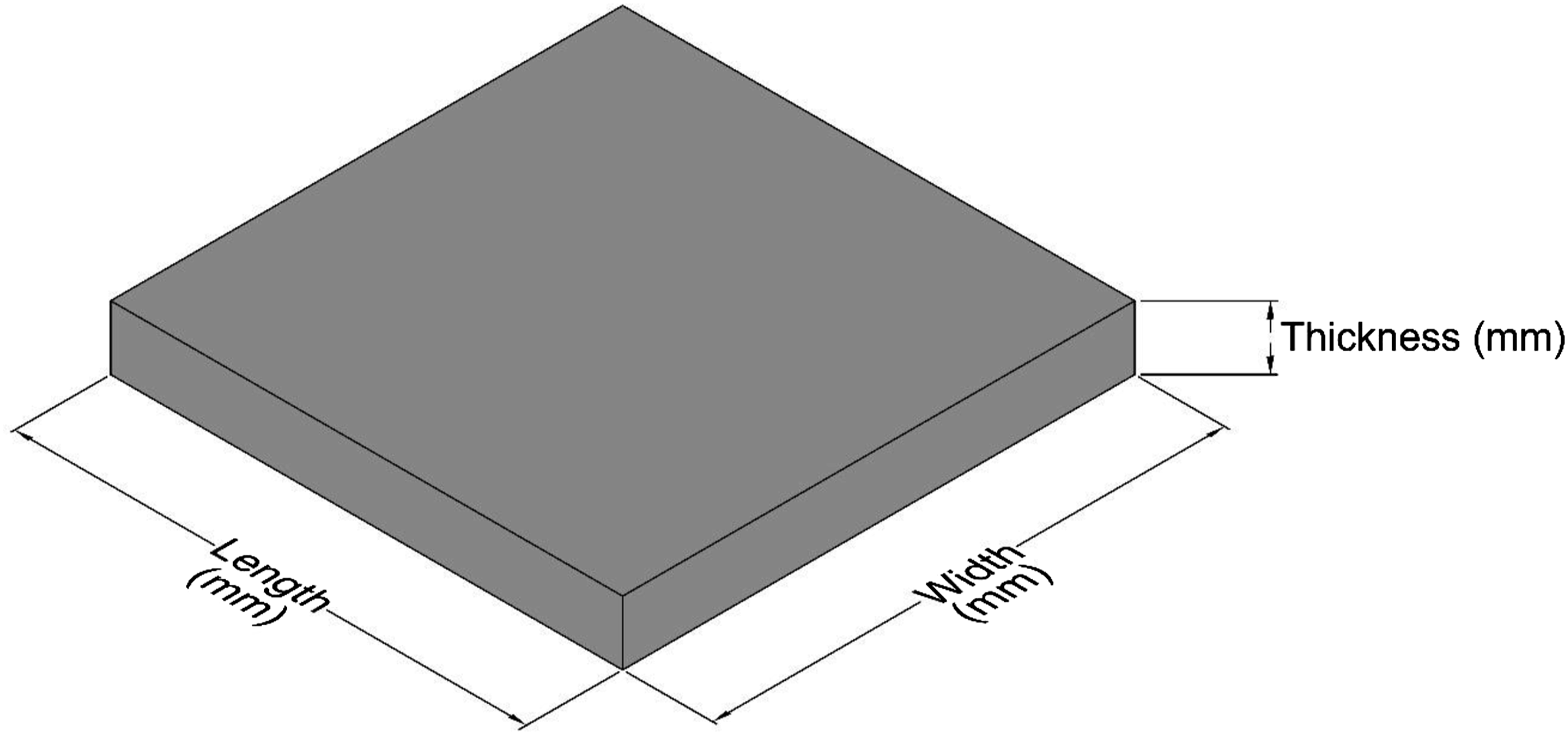
Printing parameters
Specimen print parameters.
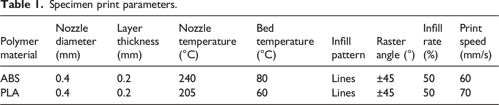
Print parameters relating to the nozzle temperature, bed temperature and print speed were the default values for each material as recommended by the manufacturer. However, parameters such as layer thickness, infill pattern and infill rate have previously been shown to be influential factors affecting the mechanical properties of parts manufactured via ME (Sheoran and Kumar, 2020), specifically their stab resistance (He et al., 2018). As such, layer thickness was set to 0.2 mm, while the infill pattern was selected as ‘lines’ with +45° and −45° angles for subsequent layers, as illustrated in Figure 2. Infill pattern of subsequent layers.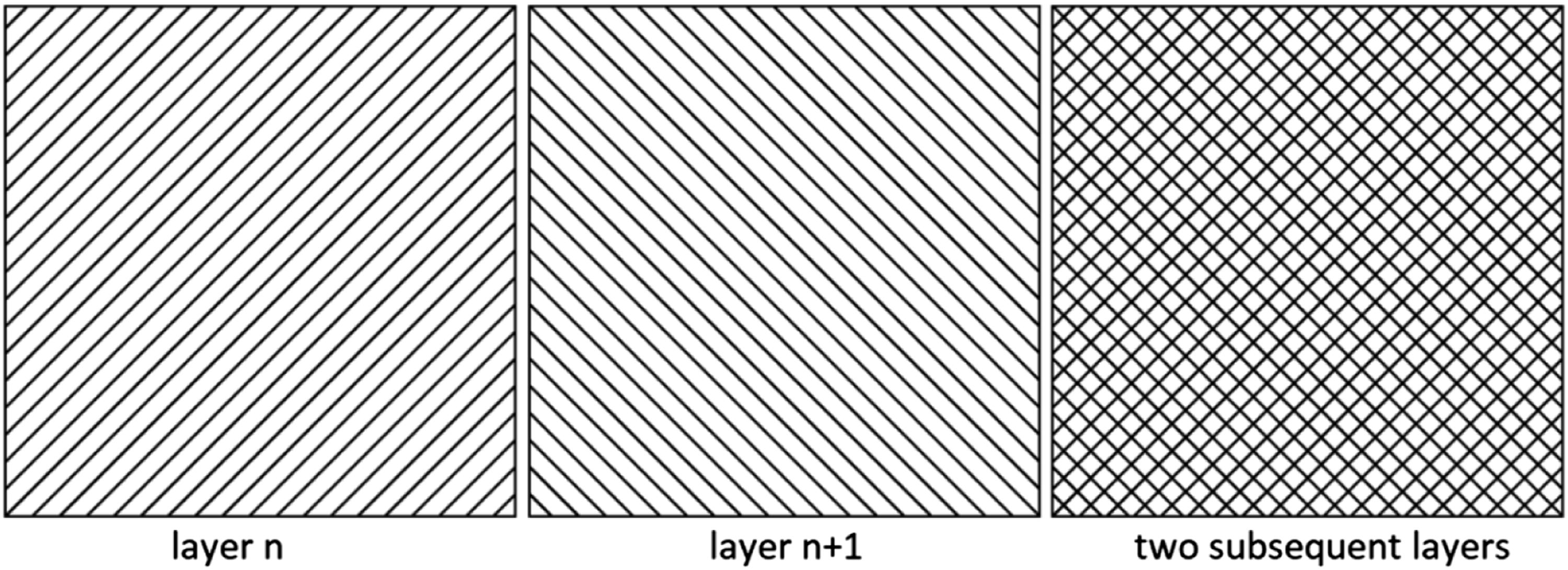
In addition, an infill rate of 50% was selected for standardisation across all specimens, as the main aim of this investigation was to determine the effect of specimen size on the stab resistive performance rather than how infill rate affects such. Apart from those mentioned, all other print preparation parameters were set to the default values as recommended by the slicing software and material manufacturer.
Test specimen manufacture
All test specimens were manufactured using an Ultimaker3 3D printer (Ultimaker B.V., Utrecht, Netherlands) housed within a fully enclosed chamber with the intention of minimising any external thermal influences that may occur during printing, such as material shrinkage and the development of internal stresses (Espalin et al., 2014). Four replicas per specimen were printed across two materials: 120 test specimens in total, 60 ABS and 60 PLA. To minimise the likelihood of any manufacturing variance among the specimens that could potentially affect the validity of the results, that is, sample distribution on the built plate, each test specimen was located within the centre of the build plate during its manufacture. Following such, each manufactured specimen was assigned a unique identification code for traceability.
Stab test methodology
Stab test drop tower
All stab tests were performed according to the KR1-E1 protection level of 24 joules of energy, as outlined in the UK HOSDB body armour standard (Payne et al., 2017) using a HOSDB gravity driven guide rail drop tube assembly, as shown in Figure 3. HOSDB rail drop tube assembly (left) and test-bed in detail (right).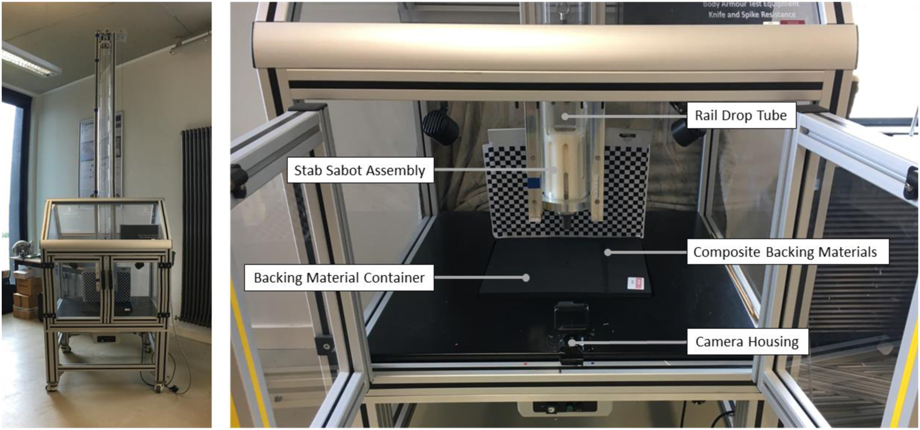
This drop tower apparatus facilitates the dropping of the knife attached to a sabot to fall under the influence of gravity from a pre-determined height corresponding to the required impact energy of 24 J and to strike an armoured specimen at a pre-determined point of impact, which for the purposes of this investigation was the centre point of the specimens top surface (Croft and Longhurst, 2007b; Payne et al., 2017).
Stab sabot assembly
The stab sabot assembly, as shown in Figure 4 (Payne et al., 2017), consisted of a sabot casing, a knife holder, two damper discs and a knife, weighing in total approximately 1900 ± 20.5 g (Croft and Longhurst, 2007b; Payne et al., 2017). Schematic of the stab sabot assembly.
Two damper discs manufactured from closed-cell polyethylene foam Plastazote® LD3 acting as damper were placed behind the knife holder. Each damper disc was 50 ± 0.5 mm in diameter and 30 ± 1 mm in thickness (a collective thickness of 60 ± 1 mm) and was stored flat for a minimum of 24 hours prior to use. These damper discs were replaced with virgin damper disks following five strikes (Croft and Longhurst, 2007b; Payne et al., 2017).
Test knives
HOSDB P1/B test knives designed to replicate the broad spectrum of knives used in assaults on police officers were used in this study (Croft and Longhurst, 2007b; Payne et al., 2017). Before use, each knife was wiped clean with acetone solution without damaging the knife tip (Payne et al., 2017).
Composite backing materials
A composite backing material pack as outlined by Payne et al. (2017), imitating the compressible surface and resistance of the human body was used (Chadwick et al., 1999) and consisted of sheets measuring 400 × 333 mm in length and width in the following order from top to bottom including: • 2 × 8 mm sheets of AL52N (expanded nitrile/NBR sponge), • 1 × 8 mm sheet of DK1735 (expanded firm neoprene sponge rubber), • 1 × 30 mm sheet of LD24 (plastazote® closed-cell polyethylene foam), • 2 × 6 mm sheets of AL55 (solid natural rubber).
These sheets were placed beneath the armour test specimens and thermally conditioned within the test environment for at least 12 hours prior to the stab testing (Croft and Longhurst, 2007b; Payne et al., 2017). Also, they were replaced with virgin ones when they became visibly damaged as outlined by the UK HOSDB standard (Payne et al., 2017).
Test environment and conditions
Stab test requirements.
By using the total mass of sabot assembly, the 24 J stab impact energy requirement of KR1-E1, and the force of gravity, the estimated height, at which the knife sabot was released, was calculated using equation (1)
To generate 24 J stab impact energy, it was established that a distance of approximately 1.30 m was required between the tip of the knife and the top surface of the test samples.
Additionally, the order in which the manufactured specimens were stab tested was randomised to minimise the effects of any uncontrollable and unforeseeable variables that may affect the validity of the test results (Johnson et al., 2015).
Recording blade penetration
Penetration depth is the key factor for assessing the stab resistive performance of armours following a stab impact test (He et al., 2018). This is because the loss of impact energy causes damage to armour specimens by the knife through its penetration. Hence, measuring the penetration depth is an appropriate way of assessing the stab resistance of such armours. When measuring the stab penetration depth, there were two suitable methods to be utilised depending on the depth of the stab, as illustrated in Figure 5 (Croft and Longhurst, 2007b; Johnson et al., 2017; Payne et al., 2017). 1. Measuring the cut length within the Polyart® 140 g/m2 synthetic witness paper, placed between the test specimen and the top layer of the backing material pack and calculating penetration through the use of equation (2) 2. Direct measurement of penetration between sample and tip of the knife using a digital calliper through the underside of each specimen. Representation of cut length (left), direct measurement of the blade penetration depth (right).

Back-face signature test methodology
It was hypothesised that the size of a test specimen could have an effect on BFS – where BFS is a measure of depression of an armour sample into the backing material the following impact. Therefore, an extra specimen was manufactured per size and thickness group for BFS tests.
Slow-motion video captures were taken during stab tests to analyse BFS. For this, a GoPro HERO 7 camera was mounted onto the stab test-bed with a clear line of sight to the test specimen and knife impact zone. The quality of the videos was set to 1080 pixels at 60 fps, and a chessboard pattern board was also placed behind the test specimen and in view of the camera. In addition, a reference guide measuring 20 mm was aligned parallel with the test specimen and was positioned on the test-bed to provide an appropriate datum, that is, supporting the pixel-distance conversion and calibration. Impact footage was analysed using GoPro Studio video analysis software and an image at the moment of maximum BFS was captured and transferred to ImageJ (version 1.53e, U.S. National Institutes of Health, Maryland, USA) which is an image processing and analysing software, to be analysed. To support image analysis, a scale for each image was set with the help of the 20 mm reference datum, and the remaining visible thickness of the test specimen, which was therefore subtracted from the total thickness of the test specimen in order to determine its BFS.
Stage two: minimum thickness determination
Test specimen materials
Six commercially available Ultimaker polymer filaments were used for the manufacture of test specimens including polycarbonate (PC), acrylonitrile butadiene styrene (ABS), polylactic acid (PLA), tough PLA (TPLA), nylon (PA) and thermoplastic polyurethane (TPU).
Test sample geometry
Informed from the findings from stage one, each specimen measured 50 × 50 mm in length and width. Two initial thicknesses, 6 and 8 mm were set per material. From the stab performance of 6 and 8 mm thick samples tested, the decision was taken to manufacture more specimens with thickness either less than 6 mm, or greater than 8 mm, or 7 mm. To do so, a thickness decision making mechanism (DMM) was adopted, as shown in Figure 6. Thickness determination mechanism for planar test specimens.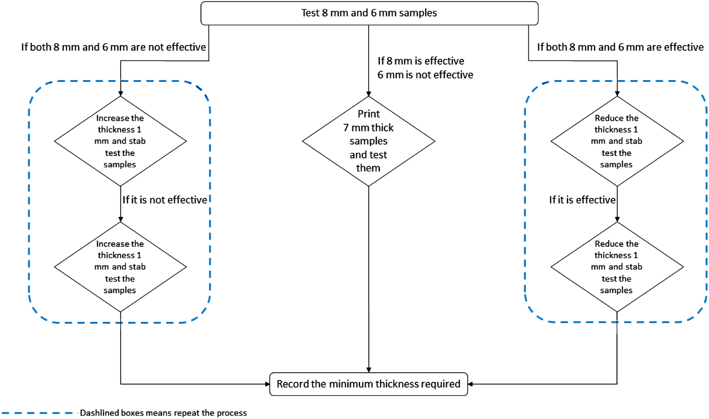
Five replicas per thickness were built for each material and they were assigned a unique ID consisting of M-T-n (M for material type, T for thickness, n for print order) following their manufacture.
Test specimen design and manufacture
Print parameters of specimens.
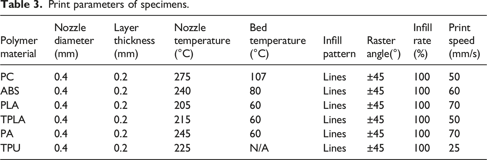
Layer thickness, infill pattern and raster angle were consistent with those utilised in stage one. Also, in stage two, the infill percentage of 100% was utilised in order to provide the appropriate control of specimens against stab impacts. Additionally, the colour of materials was kept white where applicable to minimise the effect of filament colour that could potentially have on the mechanical performance of specimens. All other print parameters were set to default values recommended by the slicing software and material manufacturer.
Experimental design
The stab test order of 6 and 8 mm thick specimens was randomised in an attempt to avoid any noise factors that could potentially affect the validity of the test results. Following the outcome of testing these initial thicknesses and according to the outcome of the DMM previously presented in Figure 6, incrementally thicker or thinner specimens were manufactured and stab tested in random orders.
Stab test methodology
All stab tests were conducted according to the stab test methodology previously outlined. The critical stab penetration depth of a knife was determined as 8 mm according to the UK HOSDB standard (Payne et al., 2017). Hence, specimens demonstrating less penetration than 8 mm were accepted to be effective at providing stab resistance against 24 J of impact energy while others were assessed to have failed the stab test. It should be also noted that BFS was not assessed in the scope of stage two.
Results and discussion
Stage one: geometry characterisation
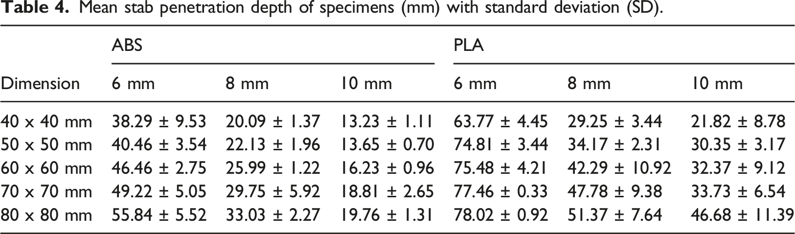
Mean stab penetration depth of specimens (mm) with standard deviation (SD).
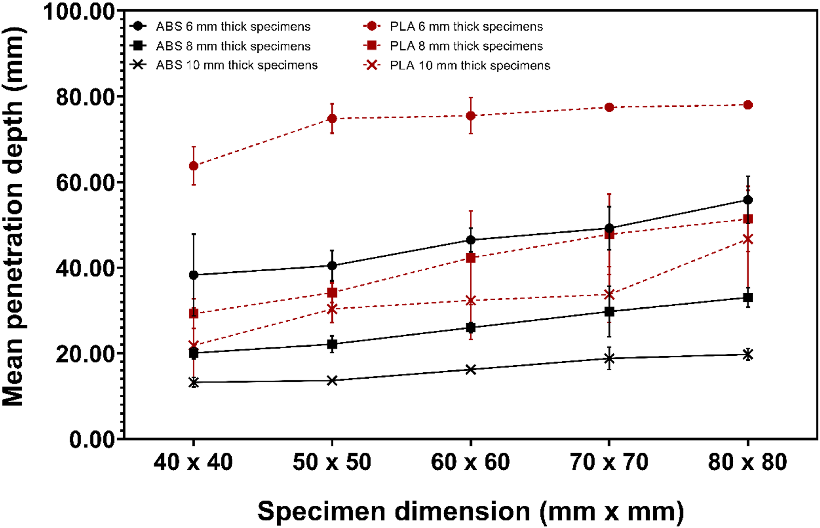
Stab test results of ABS and PLA materials.
The presented results documented that the stab performance assessment of material extruded specimens could be approached from three factors: specimen size, thickness and material type.
Regarding the specimen size, the smaller geometries demonstrated more successful levels of resistance to stab impact energies than larger ones. In other words, as the geometry increased in length and width, there was a visible reduction in stab protection since mean blade penetrations increased.
Thickness was a significant factor since thicker specimens were shown to be more capable of resisting stab impact energies than thinner specimens. This is more likely due to the need for more impact energy for the perforation as expressed by Horsfall et al. (2013), in which thicker samples or more successive layers need more impact forces to be perforated (Horsfall et al., 2013). However, an increase in the thickness of such solutions also results in an increase in product weight and manufacturing cost (Weerasinghe et al., 2020).
Additionally, ABS and PLA samples in the same dimensions in terms of length, width and thickness responded differently to the stab impact energy of 24 J, which ABS specimens were more successful than PLA ones when exposing the impact. This outcome of stage one raises questions in relation to the potential stab performances of a wider range of ME materials.
When stab testing PLA specimens, most of the specimens demonstrated a degree of fragmentation upon the impact, as shown in Figure 8. This presence was not observed with ABS specimens, which can be possibly associated with the brittle nature of PLA compared to ABS (Vidakis et al., 2020). Also, it can be argued that PLA is not a suitable material for SRBA applications as the material is brittle and exhibits a high elastic modulus and bending modulus, which may produce low flexibility in the final garment style product assemblies (Gong et al., 2019). Fragmentation behaviour of PLA samples.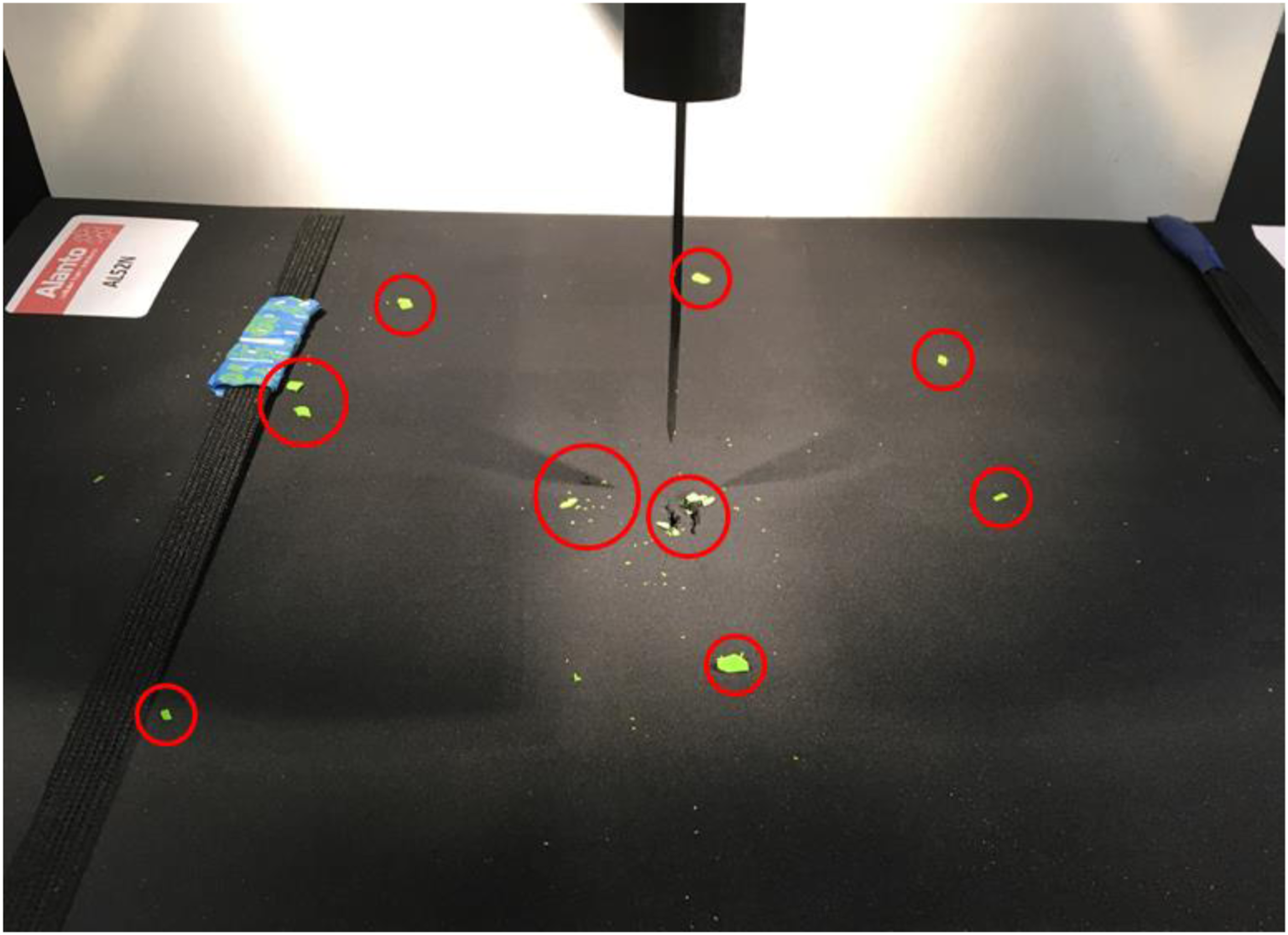
Moreover, two PLA specimens demonstrated catastrophic fractures in which the knife was fully absorbed by the composite backing materials and penetration measurements were not possible for those demonstrated in Figure 9. Fractured PLA specimens 50 × 50 × 8 (left) and 80 × 80 × 6 (right).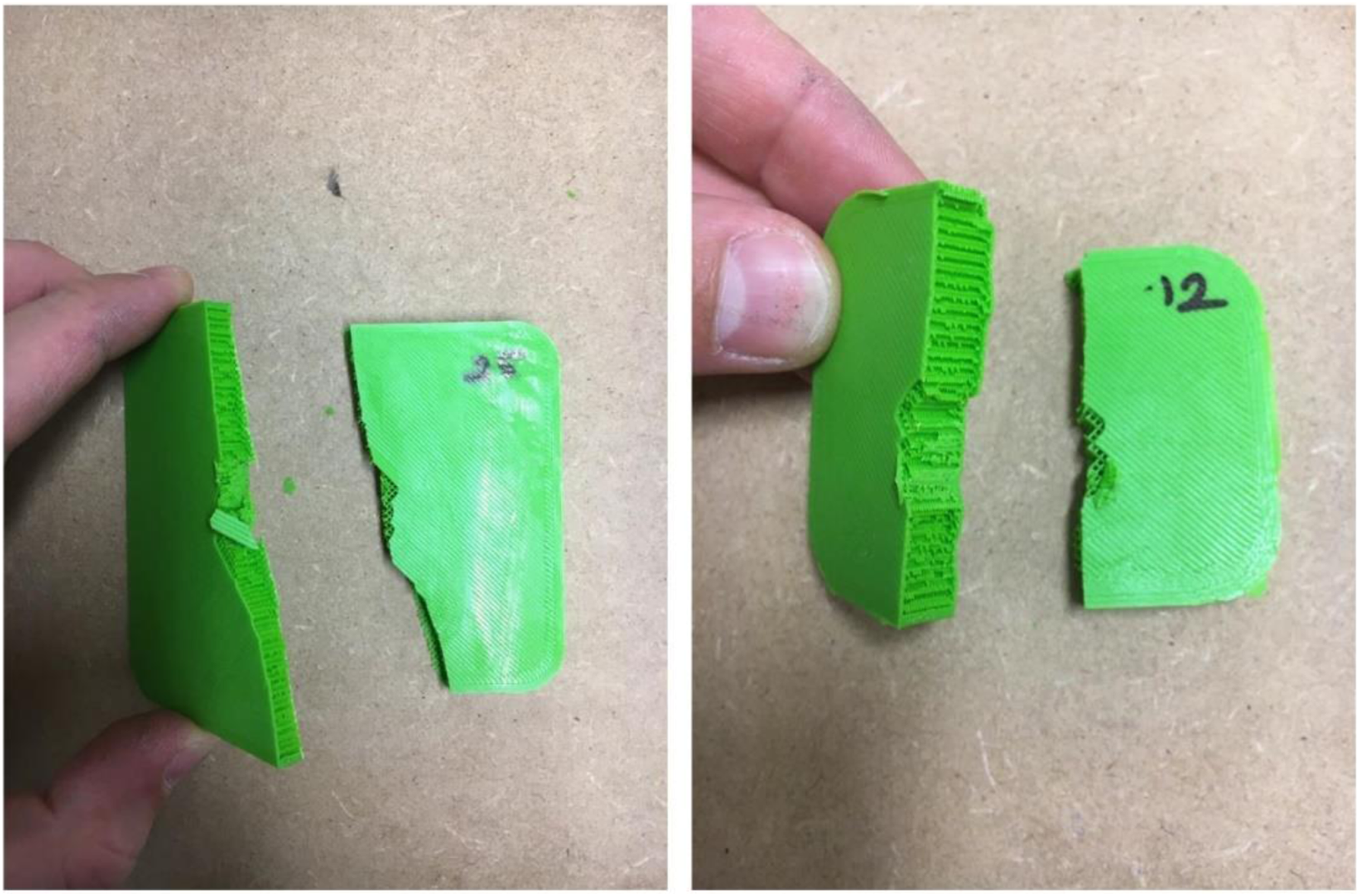
In terms of the ABS test specimens, no fracturing occurred in any of the samples, however, one specimen experienced some degree of delamination upon impact, as shown in Figure 10. Delamination in ABS sample of 70 × 70 × 10.
When compared to other replicas of 70 × 70 × 10 ABS specimens, the delaminated ABS recorded approximately 4 mm greater penetration than its counterparts, with a penetration depth of 22.78 mm. This failure was likely a result of a manufacturing error such as sudden temperature change during cooling, air exposure, or temperature fluctuations across the print bed or nozzle during manufacturing (Aitchison and Wang, 2019).
From the stab test results of stage one, 40 × 40 mm specimens for both ABS and PLA materials demonstrated the greatest levels of stab resistance against the UK HOSDB KR1-E1 stab impact energy of 24 J. Also, it was clearly seen that different parameters such as overall specimen dimensions, specimen thickness and the material type were factors that influenced the stab resistive performance of such specimens.
Stage one: back-face signature test results
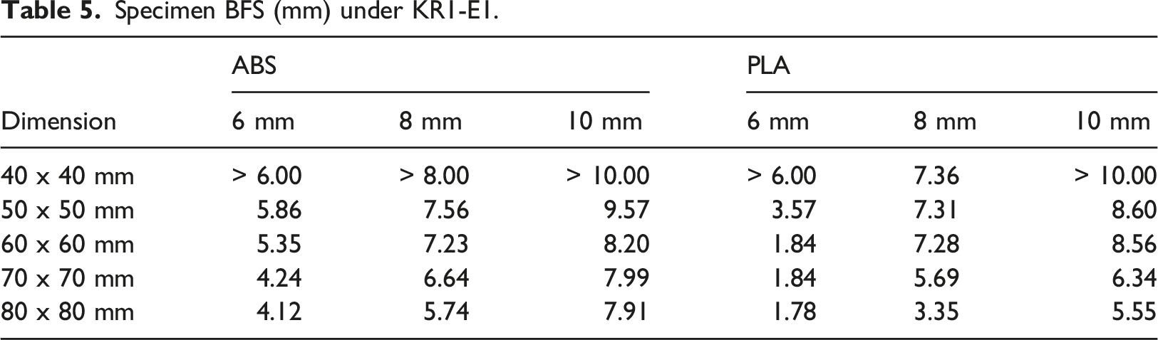
Specimen BFS (mm) under KR1-E1.
The BFS results indicated that the measured BFS was influenced by the overall dimensions of test specimens, as well as their thickness, and material type. Therefore, the results can be assessed in terms of these three factors.
It is clear from Table 5, an increasing trend in BFS was observed as the size reduced, that is, the recorded BFS reduced as the dimension of specimens in length and width increased. So, 80 × 80 mm samples of both ABS and PLA had less BFS among all five of the specimen sizes. However, BFS was not measurable for five out of six 40 × 40 mm samples as the specimens were fully absorbed within the composite backing material; therefore, line of sight to the camera was not possible. As a result, no video and photo analyses were possible for these specimens, and therefore their BFS values were accepted to be greater than the specimen’s nominal thickness. The only exception was that the 40 × 40 × 8 PLA sample had 7.36 mm of BFS being very close to its total thickness of 8 mm.
When the results were assessed in terms of specimen material type, the PLA specimens typically demonstrated lower recordable BFS than ABS specimens within the same dimensions and thicknesses. The only exceptions were 60 x 60 x 8 and 60 x 60 x 10 ABS samples which showed less BFS than their PLA counterparts. Another interesting result was that the BFS of 6 mm thick PLA specimens, except for those within the 40 × 40 mm category, were considerably lower in comparison to 6 mm thick ABS specimens.
Further, within the same material category, as the thickness increased for the same size, higher recordable BFS was experienced. For example, 10 mm thick ABS sample demonstrated more BFS than 8 and 6 mm thick ABS samples. This is likely to be due to the perforation phase within the stabbing process where the knife perforates the rear face of the armour sample and therefore takes longer to complete for the thicker plates, thus resulting in the armour samples being pushed into the composite material pack back for a longer time, and consequently demonstrating greater levels of BFS, in comparison to thinner structures.
Additionally, the interconnected relationship between mean stab penetration depth, BFS and specimen size was compared and illustrated in graphs in Figure 11. Interconnected relationship between mean stab penetration depth, BFS and specimen size.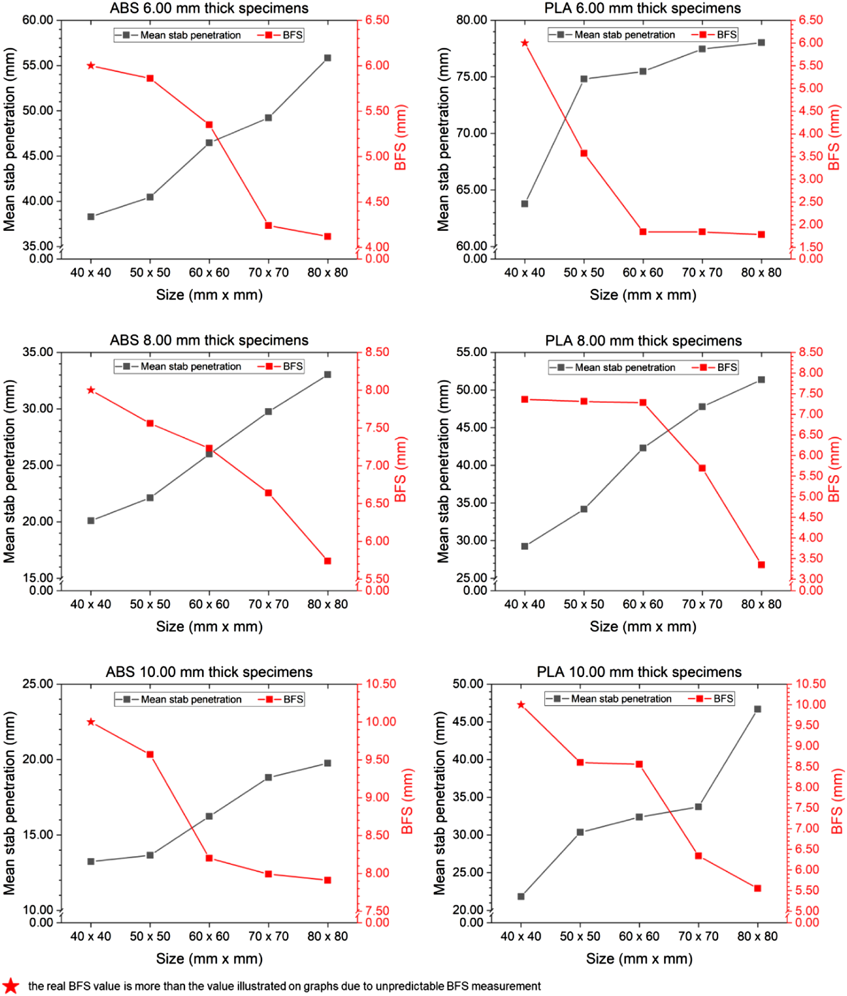
According to Figure 11, it is clear that stab penetration depth reduced as the specimen size reduced; however, this resulted in an increase in BFS. The possible explanation for this occurrence could be attributed to the transition from the perforation phase to the penetration phase. If perforation of the knife takes longer, as it has not started the penetration upon impact yet, it uses the impact energy to push the armour specimen towards the backing material pack and results in a greater level of BFS. Similarly, if the penetration stage takes longer than perforation, the knife utilises more of the impact energy for its penetration, therefore resulting in less BFS due to the quick transition from perforation to penetration. It could be concluded that as the size gets larger, more of the impact energy is used for the penetration stage rather than perforation as the knife quickly starts penetrating transiting from perforation and vice-versa. Therefore, a balance between those parameters should be achieved and considered when designing material extruded stab resistant armours.
The results from stage one established that the required optimum size of a planar body armour specimen measured should be 40 × 40 mm when considering overall stab protective performance, while 80 × 80 mm specimens caused the least BFS performance. However, all measured BFS were within the minimum allowed limit of 25 mm of the UK HOSDB (Croft and Longhurst, 2007a) apart from 40 × 40 mm specimens having unpredictable BFS due to being fully pushed into the backing material pack and as such were unable to fully determine their true BFS. Therefore, stage two focused on the stab performance of 50 × 50 mm additively manufactured specimens.
Stage two: minimum thickness determination
Mean stab penetration depth of specimens (mm) with SD.
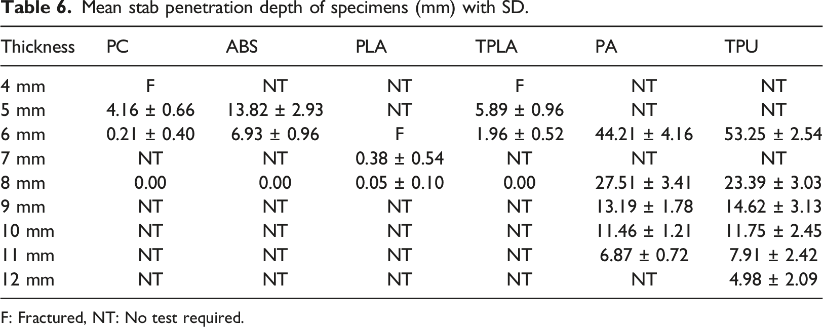
F: Fractured, NT: No test required.
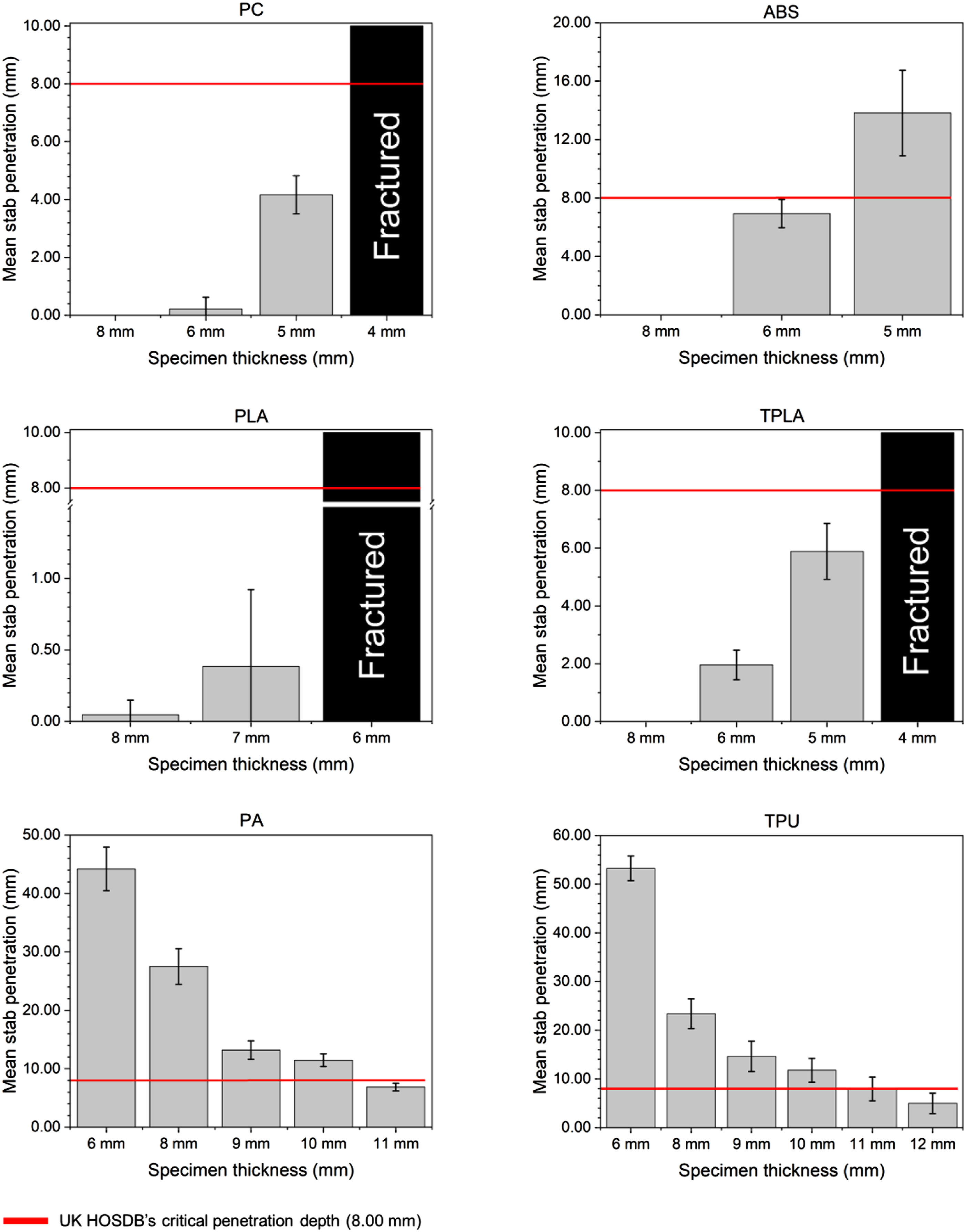
Mean stab penetration depth of different materials.
Data acquired from stage two revealed that PC and TPLA materials clearly demonstrated their effectiveness at providing stab protection against the UK HOSDB KR1-E1 impact energy of 24 J with thinner structures compared to other materials tested. Specimens manufactured using PC and TPLA across initial specimen thicknesses of 6 and 8 mm proved to be effective at providing stab protection. Similarly, 5 mm thick specimens demonstrated a knife penetration depth below the 8 mm acceptable limit with a mean penetration depth of 4.16 mm for PC and 5.89 mm for TPLA. Further investigations of 4 mm thick PC and TPLA specimens could not be conducted since all specimens catastrophically fractured upon impact, as shown in Figure 13; therefore, such was considered to exceed the permittable limit due to unpredictable knife penetration measurements. Fractured 4 mm thick PC (left) and TPLA (right) specimens.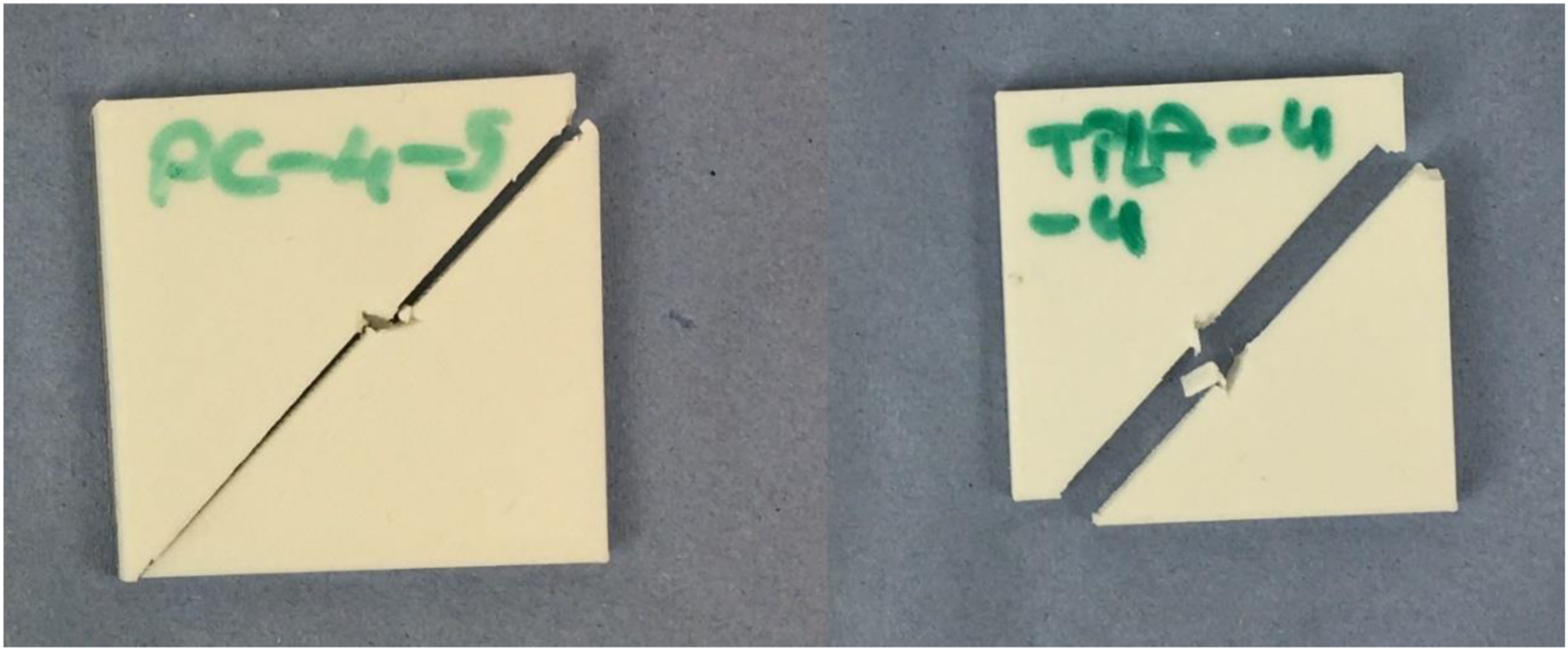
The stab resistant performance of PC and TPLA materials also identified a degree of damage to most of the test knives upon impact, as shown in Figure 14. Knife tip comparison: damaged knife tip upon impact vs undamaged knife tip.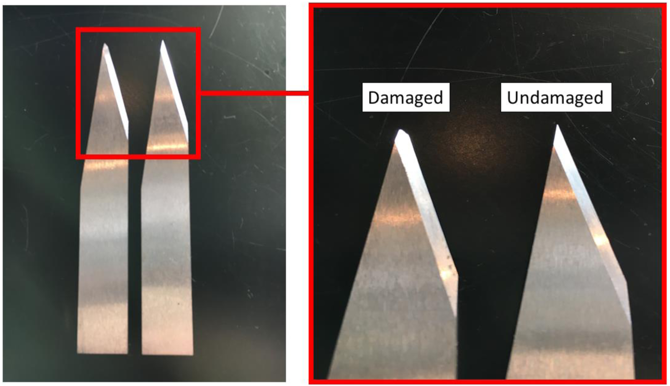
The reason for blade failures was explained by Johnson et al. (2018a) that it was a likely result of transferring impact energy away from the knife once impacted with the test sample; therefore, damaging the test blade which was the least resistive pathway (Johnson et al., 2018a). Also, the results of the material extruded PC specimens aligned with the performance of PC specimens manufactured by hot pressing, where a minimum 5.45 mm thickness was required to successfully withstand 24 J of impact energy within the allowable 8 mm penetration limit (Guo et al., 2020).
Following PC and TPLA, ABS test specimens measured 8, 6 and 5 mm in thickness according to the DMM. Although all the 8 mm thick ABS specimens demonstrated excellent levels of stab resistance against 24 J impact energy with no proof of penetration, the mean penetration value across the 6 mm thick specimens was 6.93 mm, of which some demonstrated a very close penetration depth to the 8 mm threshold of HOSDB standards – maximum 7.89 mm and minimum 5.65 mm. As such, a series of 5 mm thick ABS specimens were evaluated and recorded a mean blade penetration of 13.82 mm – with a minimum penetration of 10.32 mm and maximum penetration of 18.07 mm. All 5 mm ABS specimens failed to demonstrate an appropriate level of knife protection to the UK HOSDB KR1-E1 impact energy of 24 J, and no further tests with ABS specimens below 5 mm thick were therefore performed.
For the PLA specimens within stage two, four of five 8 mm thick specimens registered no blade penetration, while specimen PLA-8-3 demonstrated a minimal penetration of 0.23 mm. However, all the 6 mm thick PLA specimens were ineffective at providing stab resistive performance against 24 J of impact energy, instead catastrophically fractured into two pieces upon impact, as shown in Figure 15. Fractured 6 mm thick PLA specimens.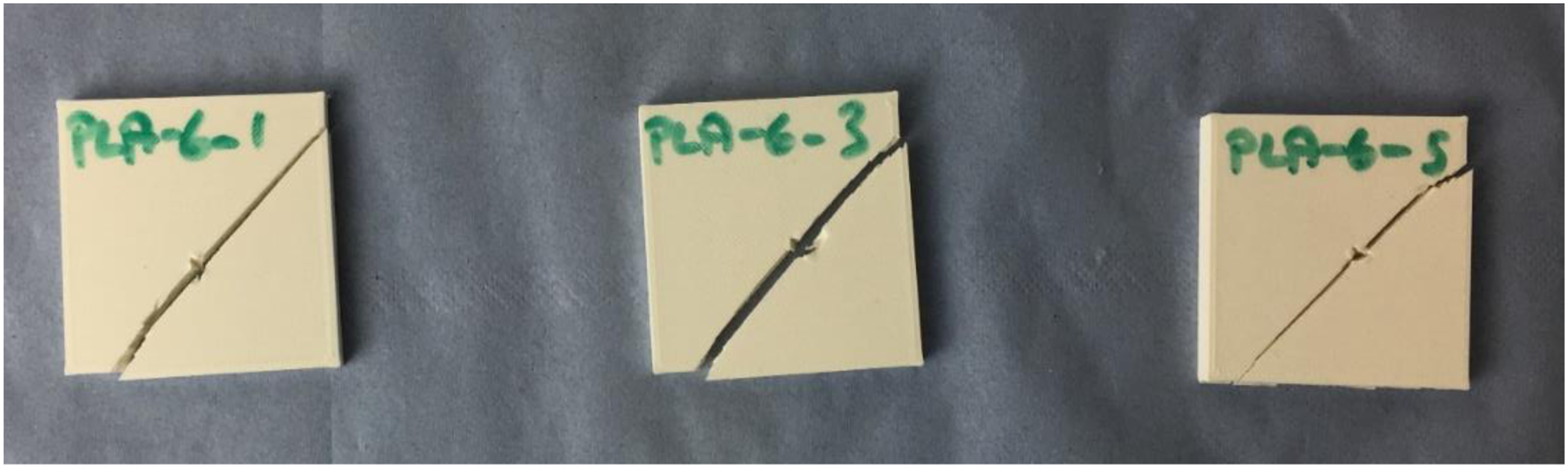
Based on the indicative protective performances of both the 8 and 6 mm specimens, a set of five 7 mm thick specimens were prepared and stab tested. When evaluating the performance of the 7 mm thick specimen set, no penetration was recorded for three of five samples. However, specimens PLA-7-1 and PLA-7-4 demonstrated minimal blade penetration – 1.12 mm and 0.80 mm respectively, significantly within the HOSDB defined limit. Within the investigation of PLA, it can be concluded that based on the thicknesses evaluated within stage two, a minimum planar thickness of 7 mm is required when using PLA. However, further evaluation is required to establish an optimal minimum thickness required for PLA material between 6 and 7 mm. Additionally, when compared to TPLA tested specimens, those manufactured from PLA also supported the idea that there could be an association between the toughness of the material and its stab resistive performance as explained by Cheon et al. (2020) as TPLA were more successful than PLA samples at resisting against impact forces at a lower planar thickness (Cheon et al., 2020).
After 6, 8, 9 and 10 mm, PA planar specimens demonstrated knife penetration in excess of 44.21, 27.51, 13.19 and 11.46 mm, respectively – far beyond the HOSDB 8 mm permissible limit. A successful stab protection was attained with PA manufactured planar test specimens at a thickness of 11 mm – demonstrating a mean knife penetration depth of 6.87 mm. Of the PA specimens tested, a maximum penetration of 7.71 mm was demonstrated by specimen PA-11-4, which can be concluded that the minimum thickness required for the PA specimens was 11 mm which was significantly thicker than previous materials tested.
TPU was the material requiring the thickest structure to provide protection within the UK HOSDB standards. 6, 8, 9 and 10 mm thick specimens demonstrated a mean penetration of 53.25, 23.39, 14.62 and 11.75 mm, respectively – all exceeding the permitted limit. While the 11 mm thick TPU specimens demonstrated a mean penetration depth of 7.91 mm, the protective performance of specimens at this thickness was inconsistent, and as such 12 mm thick TPU specimens were there first thickness group to demonstrate a consistent level of protection against knife penetration – with a mean depth of 4.98 mm. From the results, the required minimum thickness for TPU was found to be 12 mm – significantly thicker than other materials. As such, due to their low impact strengths, PA and TPU stab protective solutions require thicker structures in comparison to using alternative materials. Armours of such thickness may result in greater overall product weight (Weerasinghe et al., 2020) and therefore being greater than the conventional SRBA, which may also contribute to physiological difficulties, such as back injury and heat stress, for the wearer (Johnson et al., 2015; Yuan et al., 2017a). Therefore, PA and TPU are not recommended in material extruded SRBA applications.
The results presented demonstrated that the minimum thicknesses required for material extruded specimens to provide knife protection within the UK HOSDB KR1-E1 performance requirements were 5 mm for PC and TPLA, 6 mm for ABS, 7 mm for PLA, 11 mm for PA and 12 mm for TPU.
Conclusion and future work
This study set out to assess the stab performance of planar SRBA specimens manufactured via ME, in terms of their specimen size effect on penetration depth and back-face signature, and the minimum specimen thickness required to provide stab protection within the UK HOSDB standards. Results from this work have highlighted a number of key findings to support the future design and development of material extruded SRBA, including: • stab resistive and BFS performance of additively manufactured SRBA specimens depend on three main factors: specimen size, thickness and material type. • smaller geometries were more capable of resisting the stab impact energy and having less penetration rather than larger ones; however, they experienced greater levels of BFS, and vice-versa. This is because the transfer of the impact energy from the perforation stage to the penetration stage is dependent on specimen size. Therefore, a balance between specimen size and penetration and BFS is required. • thicker samples can resist more impact energy to be penetrated as perforation takes longer than penetration compared to smaller ones. However, thicker samples might result in more weight in additively manufactured SRBA compared to conventional ones. Therefore, a balance between thickness and weight should be achieved to provide more flexibility and mobility for the wearer. • PC and TPLA among all tested materials were the most successful at providing stab protection against KR1-E1 stab threats with thinner structures measuring 5 mm. This could be attributed to their better mechanical properties compared to other materials tested and also supports the idea that the mechanical properties of such specimens are the primary property to be considered in the case of evaluating the stab performance (He et al., 2018). However, further investigation is required.
It is also important to note some limitations to this work and opportunities for future development. For example, this research focused on the use of planar specimens, therefore an opportunity exists to explore the stab resistive behaviour of non-planar specimens. Material choice was limited to six ME materials in total, so a wider material choice is needed. Since there is no appropriate stab test procedure for assessing the stab performance of additively manufactured body armour samples, all stab tests were conducted within the latest UK HOSDB body armour standard for traditional aramid fibre and polycarbonate armour systems. Lastly, it should be noted that the results of this study could differ depending on the material extrusion system and material utilised, as well as print parameters.
In all, it is believed that a fundamental step towards the future body armours research is achieved with proposed protective structures which will be directly applicable to the development of both rigid and flexible additively manufactured body armours being capable of providing stab protection to domestic security and law enforcement personnel. Also, the outcomes of this work clearly identify the potential of such structures and define a number of opportunities for future SRBA research, including: • additional investigations on developing linkage methods of individual specimens manufactured via ME in order to establish a wearable protective solution. • further examination of a wearable body armour garment in terms of protective performances and operational suitability such as flexibility and mobility. • explore the utilisation of technical fibres with a view to establishing composite-based AM structures for enhanced SRBA protection. • evaluation of the flexibility, manoeuvrability and damping effect of additively manufactured protective samples and their effects on the protection performance of such structures.
Footnotes
Declaration of conflicting interests
The author(s) declared no potential conflicts of interest with respect to the research, authorship, and/or publication of this article.
Funding
The author(s) received no financial support for the research, authorship, and/or publication of this article.
Author’s note
This study is a part of PhD research sponsored by the GREAT Scholarships of the British Council.