
Abstract
Induction heating is a non-contact-based energy source that has the potential to quickly melt the metal and become the alternate energy source that can be used for additive manufacturing. At present, induction heating is widely used in various industrial applications such as melting, preheating, heat treatment, welding, and brazing. The potential of this source has not been explored in the additive manufacturing domain. However, the use of induction heating in additive manufacturing could lead to low-cost part fabrication as compared to other energy sources such as laser or electron beam. Therefore, this study explores the feasibility of this energy source in additive manufacturing for fabricating parts of metallic materials. An experimental system has been developed by modifying an existing delta three-dimensional printer. An induction heater coil has been incorporated to extruder head for semi-solid processing of the metal alloy. In order to test the viability of the developed system, aluminium material in the filament form has been processed. Obtained results have shown that the induction heating–based energy source is capable of processing metallic materials having a melting point up to 1000° C. The continuous extrusion of the material has been achieved by controlling the extruder temperature using a proportional integral derivative–based controller and k-type thermocouple. The study also discusses various issues and challenges that occurred during the melting of metal with induction heating. The outcomes of this study may be a breakthrough in the area of metal-based additive manufacturing.
Introduction
Induction heating (IH) is a non-contact-type heating technique, which is widely used for its better performance, high heating efficiency, and safety. 1 In the modern manufacturing process, IH is a valuable energy source in terms of speed, control, and consistency. Due to its rapid heating capability, IH has become a widely accepted heating method. A unique characteristic of IH is that the energy is directly released within the workpiece without affecting different neighbour elements, due to the non-contact nature of heat transfer. 2 These inherent characteristics enable it in a wide range of applications such as domestic,3,4 industrial,5,6 and medical domain.7–9 IH has also contributed to the processing of metals such as melting, 10 brazing, 11 preheating, 12 sintering, 13 and welding. 14 The IH is advantageous as compared to other traditional heating techniques such as resistance heating, flame heating, and furnaces because of its properties like the clean source of energy, fast, consistent heating, and low energy losses. 1
Additive manufacturing (AM) technology has been one of the most rapidly growing and widely explored technologies in the manufacturing 15 and medical 16 domain. AM is the process that builds the three-dimensional (3D) parts by depositing material in a layer-by-layer manner. 17 AM has the ability to fabricate parts with complex geometry with the minimum usage of material and thus offers savings in cost and time. 18 Earlier, the usage of AM was limited to prototyping, known as rapid prototyping and to polymer components only. Recently, the advances in AM technology have undergone a transformation from rapid prototyping to rapid manufacturing of end-use functional parts. AM is the process that manufactures complex parts directly from its computer-aided design (CAD) models using various materials such as polymers, metals, ceramics, and composites. Nowadays, the market demands to develop the metal-based AM technology and to fabricate the functional parts that cannot be fabricated by the conventional manufacturing processes. 19 It also demands that the developed metal AM technology should have low cost, minimum material wastage, low energy consumption, and reduced per-unit cost of the part.
Over time, different AM processes have been developed for polymer components. In the last decade, various metal AM processes have also been developed such as direct metal laser sintering (DMLS), 20 electron beam melting (EBM),21,22 selective laser sintering (SLS), 23 selective laser melting (SLM), 24 laser engineered net shaping (LENS), 25 direct metal deposition (DMD), 26 directed light fabrication (DLF), 27 wire and arc additive manufacturing (WAAM), 28 and powder bed and inkjet 3D printing (3DP). 29 These AM technology processes the metal powder or wire as an input to fabricate the metallic parts.
Powder-based metal AM processes have become a popular technology for fabricating the metallic parts. This technology uses the high energy CO2, Nd:YAG, optical fibre laser, or electron beam for melting the metal powder.30–32 The fabricated metal parts are nearly fully dense, with better dimensional accuracy and functional grade strength, which can be directly used in various applications. 33 In this process, the powder is spread in the form of a layer pattern on a build platform with the help of recoater; then, the laser is scanned in order of slice contour on the powder layer and sinters the powder particles. This process continues until the part has been completed. 34 The laser scans in different coordinates of slice contours with the help of a Galvano scanner, while some of the AM processes use the electron beam type of energy source, which requires a high vacuum chamber for fabricating the metallic parts. 35 Thus, the powder-based processes involve low material utilization, high-cost energy sources, and powder handling risks. However, wire as the feed material has a high material utilization ratio, ease in handling, availability, and low cost as compared to its powder counterpart. 19
Some of the researchers have explored the avenues by attempting metal deposition using inductive energy. Du et al. 36 developed a fused-coating technique to fabricate metal parts by processing the molten metal stream of tin-lead alloy. In their system, the metal is melted in a crucible by employing an induction heater. After that, the molten metal was ejected on the moving substrate, through the fused coated nozzle by the application of pressure in the crucible chamber. This method is popularly known as drop on demand method. Another similar work was reported by Vega et al., 37 wherein low melting point metal alloy was continuously ejected in the form of droplet by application of pressure. Some of the research has been done on the induction energy–based metal AM process. Hascoët et al. 38 developed an approach to melt metal wire with the help of induction energy. Their study shows the ability of the induction heater to directly melt the tip of metal wire and heat the substrate with the same heater simultaneously. However, the developed system is capable of melting and depositing the ferrous material, such as stainless steel (316 L), by employing a high power heater. 38 So far, however, the IH technique has not been explored in the extrusion-based metal AM process. Markedly, the application of IH with wire feedstock delivery could be highly efficient low-cost energy and sustainable process as compared to other AM processes.
In this work, the authors intend to introduce a novel idea of combining a new type of heating method with the extrusion-based AM process through this manuscript. The heating method proposed here is induction-based heating which is used to melt the metal. In this research work, an IH-based extruder has been developed for melting the metallic filament. The temperature along the extruder has been studied to obtain temperature required and is later maintained for the continuous melting of material, fed in the filament form.
Suitability of IH for AM
In AM, a different form of energy sources is used to provide the desired energy for successive material addition. These sources can be classified into two groups, namely, contact and non-contact types. 39 In contact-type energy source, as in extrusion-based AM methods, the heating element is directly connected or wrapped around the outer body of the extruder. 40 This kind of energy source works on the principle of resistance heating in which the heat is generated when the electric current flows through a resistance coil. 41 Most of the polymer-based AM processes use contact-type energy source as the low temperature is required for polymer material processing. However, this type of energy source is not suitable to generate the heat required for metal-based AM processes. As the contact-type heater will heat itself first, then it will transfer the heat to the extruder and then to the metal filament. So, resistance heating takes more time, and heat losses are high. Also, high temperature to melt the metal can be achieved when the heater size and supplied power is increased. The large heater size will eventually compromise with the system handling and overall compactness of the system. Wherein, the process of metal AM, which is a rapid manufacturing method, requires fast heating and quick response for temperature control. Therefore, non-contact-type energy sources are evolved for processing materials in metal-based AM processes. IH is one of the non-contact energy sources which quickly raises the temperature of the metallic component. Its low cost and simple design make it a potential choice among other non-contact-type sources. 42
An IH system consists of three main components, namely, user interface module, induction power supply, and induction coil, as shown in Figure 1. The interface module interrelates with the operator to control the process and adjust the required parameters according to the load condition. The heating profile of the workpiece depends on the design of the induction coil and usually restricted by its geometry. The induction power supply generates the essential current and frequency and supplies to the induction coil which is required to achieve desired electromagnetic field around the coil. 43
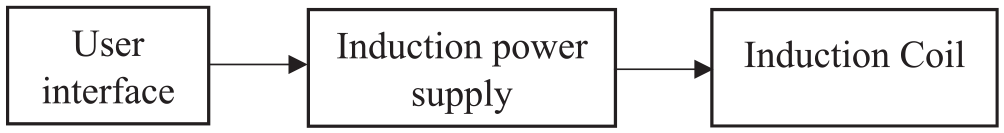
Block diagram of the induction heating system.
An IH works on the eddy current and hysteresis phenomenon. The system contains a power source, which supplies the high-frequency alternating current (AC) in the range of 20–200 kHz to the coil to generate the electromagnetic field around the coil. When an electrically conductive workpiece is kept in the vicinity of the electromagnetic field, the eddy current is induced on the surface of the workpiece, as shown in Figure 2. The induced eddy currents whirls on the metal surface (i.e. workpiece), this results in excitation of molecules inside the metal, and they start flowing in the direction of eddy current, which produces friction between molecules and results in heat generation on the metal surface. 42 Apart from the eddy currents, heat is also produced via hysteresis, which occurs only in ferromagnetic materials. In these phenomena, the alternating magnetic field forces the magnetic domains of the material to align in the direction of the magnetic lines and generate heat due to the internal friction. This effect decreases when the temperature approaches the Curie point, after which material becomes non-magnetic, and hysteresis effect diminishes. 44
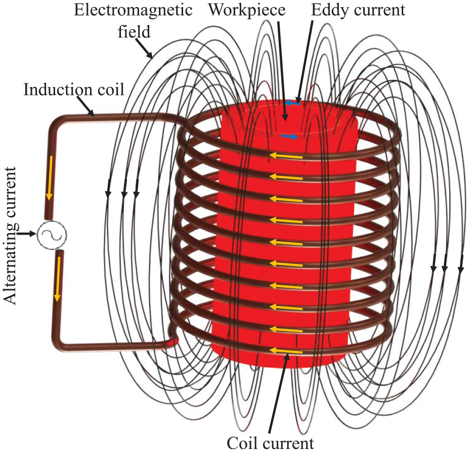
Typical induction heating principle. 42
An induction coil is an essential part of the IH system which transfers energy to the workpiece or object. The induction coil is made of copper material, which has low electrical resistivity and high thermal conductivity as compared to other low-cost metal alloys. Rapid and efficient transfer of heat owing to the high thermal conductivity makes the copper suitable for induction coil material. 42 The heating rate, effective heat length, and depth of heat penetration are affected by the geometry of the induction coil. Heat penetration depth variation with coil geometry is shown in Figure 3. The depth of heat penetration also depends on the skin depth, which effectively heats the extruder. Skin depth, d, depends on the frequency of coil current, resistivity, and relative permeability of extruder material which is given as

where
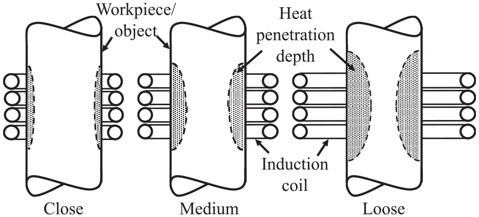
Heat penetration depth in workpiece. 42
Experimental setup
An experimental setup has been developed in order to analyse the feasibility of IH energy source for metal AM. A standard delta-type 3D printer has been used as a gantry system, as shown in Figure 4(a). It has a build volume of 140 × 140 × 250 mm3. In the delta printer, extruder head moves in three directions (X, Y, and Z), while the build platform is stationary and positioned at the base of gantry system. In it, the part deposition is done from bottom towards the top. The extruder head assembly developed in this study is bulky, as it consists of different components such as filament feeding system, cooling unit, induction coil, extruder, thermocouple, and induction heater. So, it will be a bulky design to be used with the positioning system of the Delta printer. Mounting the modified extruder head assembly with a positioning system will cause load on the positioning drives thereby, affecting the movement and accuracy of positioning drives of standard Delta printer. Therefore, the extruder head has been mounted at the top of delta printer and build platform on the positioning system, as shown in Figure 4(b). Accordingly, the existing setup of a delta printer has been modified by keeping the developed extruder head stationary and by providing movements (X, Y, and Z) to the build platform. Thus, the overall build volume was reduced to 100 × 100 × 200 mm3 due to modification. Due to the modification, the movement of axis has been provided to the build platform and now the part can be fabricated by top to bottom movement of build platform. The delta printer employs the open-source software (Repetier host) to control the positioning system. Slic3r software has been used to create the desired toolpath for part fabrication.
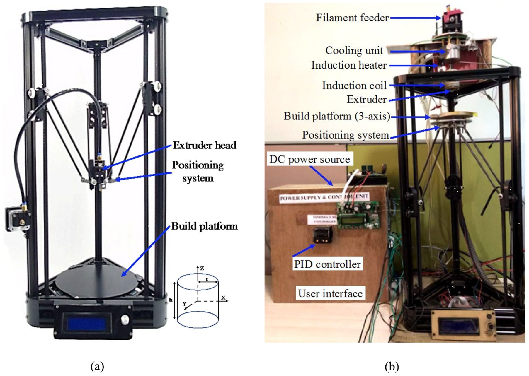
Delta-type 3D printer: (a) standard setup and (b) modified experimental setup.
In the developed extruder head, a direct current (DC) supply of 1 kW is given to the induction heater which supplies an AC and frequency of 210 A and 100 kHz, respectively, to the induction coils. An induction coil arrangement has nine number of turns, 30 mm of coil diameter, and inductance of 1.13 μH. The induction coil is wrapped around the extruder with an air gap of 12 mm between the outer surface of the extruder and inner surface of the coil (as shown in Figure 5). The induction coil provides the heat energy to the extruder. The water-based cooling unit has been used to carry out the heat from the filament entry point in the extruder. The proportional integral derivative (PID) controller has been used for maintaining the temperature of the extruder, as shown in Figure 4(b), and a manual user interface is used to input the printing metal temperature.
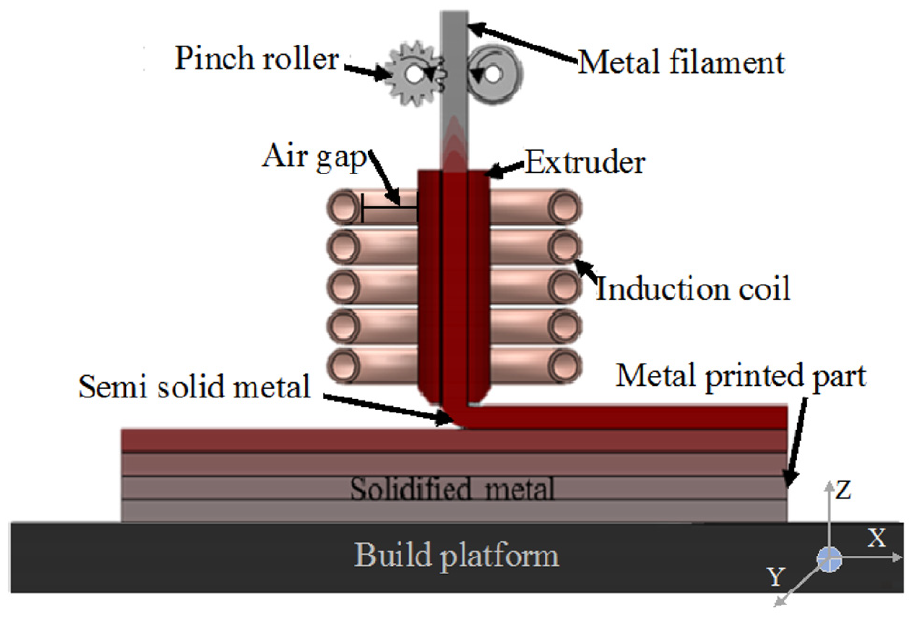
Schematic of induction-based metal additive manufacturing process.
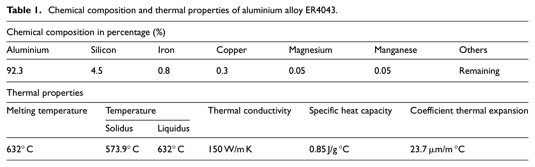
In order to investigate the extrusion capability of an inductively heated extruder, aluminium (Al) alloy (ER4043) is chosen as a wire/filament. The thermal properties and chemical composition of Al alloy material are shown in Table 1. The filament is fed into the extruder chamber using the pinch roller mechanism, as shown in Figure 5. When the filament reaches the heated zone of extruder chamber, it absorbs heat and transforms from solid state to a semi-solid state. This semi-molten form of material is extruded out from extruder through continuous feeding of the filament.
Chemical composition and thermal properties of aluminium alloy ER4043.
The selection of material for the extruder depends on the electrical and thermal properties of the metal. Extruder needs to be quickly heated and cooled inside the induction coil. Therefore, the extruder material selection is very critical. Extruder material should have high thermal conductivity, high electrical resistivity, and low thermal expansion.
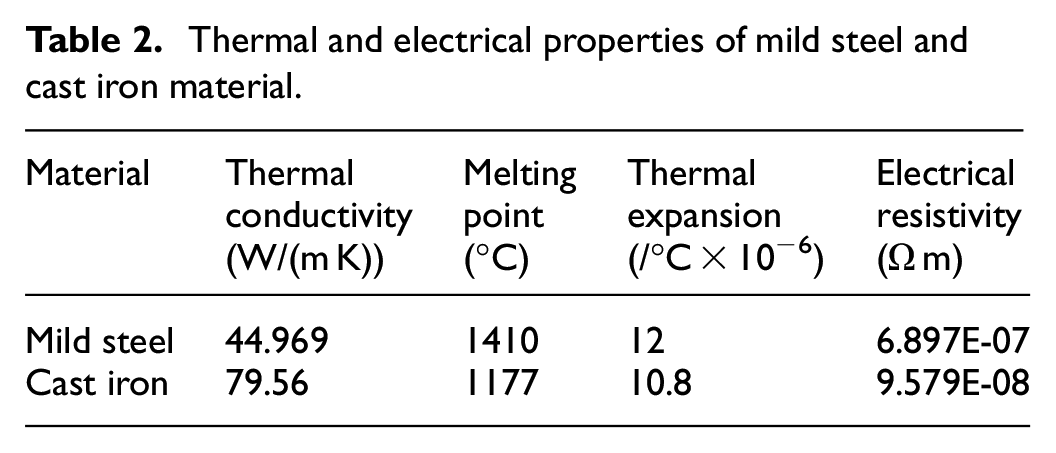
Preliminary experiments have been performed to select an appropriate material for the extruder. In this study, mild steel and cast iron are considered for extruder. Thermal and electrical properties of mild steel and cast iron material are presented in Table 2. In the experimentation, both materials are heated up to 600° C, in order to check their capability to withstand high temperature and provide a sufficient amount of heat to input filament material. Based on the results, it was observed that oxide layers or scaling are formed at the outer surface of mild steel extruder, as shown in Figure 6(a).
Thermal and electrical properties of mild steel and cast iron material.
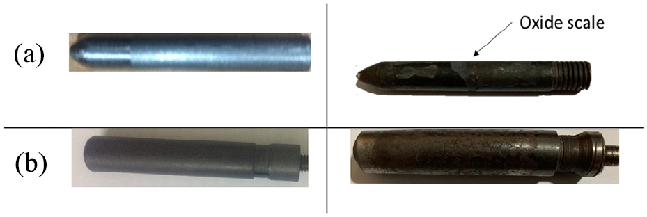
Extruder before and after heating for material: (a) mild steel and (b) cast iron.
The formation of an oxide layer on the metal surface depends on temperature. As the temperature increases, an oxide layer is formed on the surface of extruder, which reduces the electrical resistivity and magnetic permeability of the material. The oxide layer formed also reduces the effect of eddy current and hysteresis, which leads to ineffective heating of mild steel extruder. In comparison to mild steel, cast iron has a low electrical resistivity and high thermal conductivity. Experimental result shows that cast iron has a slow rate of oxide layer formation on the surface of extruder as compared to mild steel, as shown in Figure 6(b). Based on the experimental observations and considering the values of thermal and electrical properties, cast iron has been found suitable material for further experimentation.
Thermal analysis of extruder head
Temperature measurement methods of induction heated extruder
In the IH process, thermocouples and infrared pyrometers are the most commonly used instruments for the measurement of temperature. Despite the wide use of both techniques, each technique has its advantages and limitations. For the IH system, the non-contact infrared pyrometer is preferable to use. Infrared pyrometer is capable of faster response, and their measurements are not affected by the varying magnetic field. During IH, oxidation of metal surface occurs and keeps on increasing, which results in a change in the emissivity of the metal object, that is, extruder. The change in emissivity causes deviation in measured temperature; due to this, it is not suitable for the current setup. 45 However, contact-type thermocouple is capable of measuring temperature across a wide range with good precision and are robust with low cost as compared to infrared pyrometers. However, some of the literature specifies that thermocouples are not suitable for temperature measurements in the IH process because thermocouple is made of electrically conductive material and is subjected to get influenced by the alternating magnetic field during the IH process. As the literature suggested, suitable design considerations of thermocouple with a smaller diameter of nearly 0.5 mm will provide an accurate reading of nozzle temperature. The selection of the small diameter of thermocouple results in a feeble induction effect within the thermocouple hence minimizes error in the temperature reading. 46
Temperature analysis of extruder head with IH
In order to verify whether the induction heater is able to provide sufficient temperature required for melting the metal through the extruder, a thermal analysis is performed. The extruder head with IH system has been mounted on the centred position of upper frame of structure in a fixed position. To measure the temperature required to melt the metal, a k-type thermocouple of diameter 0.5 mm is inserted 4 mm inside the extruder nozzle (refer Figure 7) for measuring temperature and later removed. The k-type thermocouples are widely used for operation in a temperature range up to 1260° C. Also, it has key advantage of faster response time, low cost, and availability in small diameters. Then, induction heater provides heat to the extruder to melt the filament metal inside it for a particular time. Temperature data with respect to time have been recorded in the data acquisition system for study of variation in the temperature.
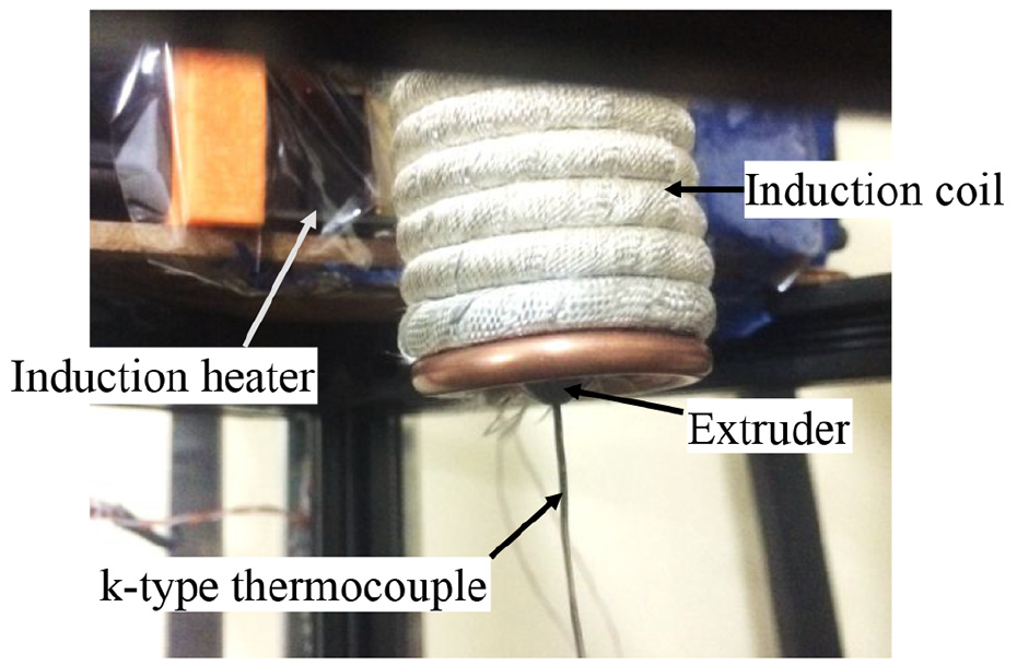
Temperature measurement of the extruder.
Figure 8 shows the temperature profile achieved in the extruder with respect to time. The obtained results show that temperature up to 1000° C was achieved within approximately 2 min, and cooling up to room temperature occurs within 15 min. It indicates that the metals having melting point less than 1000° C can be processed with ease using the developed IH-based experimental setup. In this study, aluminium in the wire/filament form has been explored, which has a melting point nearly to 632° C.
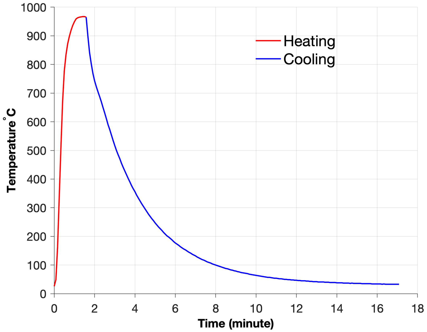
Extruder temperature profile without temperature control.
Later on, the temperature controller was incorporated in the experimental setup, and again, the temperature profile was captured. Furthermore, the temperature analysis, capabilities related to material melting, has also been determined by processing aluminium material in filament form.
There is a need to maintain the temperature within range to achieve the continuous semi-molten state of the material. Therefore, temperature analysis was extended with a controller mechanism in order to maintain extruder temperature within a particular range. For controlling the temperature of the extruder, a PID-based controller unit was used along with a k-type thermocouple. Figure 9 illustrates the block diagram of a PID-based temperature control system for an induction heater. In this system, when an AC of 250 V is supplied to a DC inverter, which produces high ampere and low voltage to drive the induction heater. Then, the induction heater produces and supplies high-frequency current to the induction coil. Due to this high current, an electromagnetic field is generated that produces rapid heat at the extruder surface. Also, it produces heat in the coil, which is cooled by the water cooling system. However, the supplied power continuously increases the temperature of extruder. A thermocouple has been used to measure the temperature of extruder. Based on the thermocouple signal, PID controller operates a relay, which in turn switches (ON/OFF) the power supply of induction heater to maintain the temperature of extruder. The recorded temperature profile of extruder is shown in Figure 10 for the set value of temperature at 580° C. The obtained results show that the temperature controller can maintain the temperature of extruder successfully at a particular set value with a variation of ±10° C.
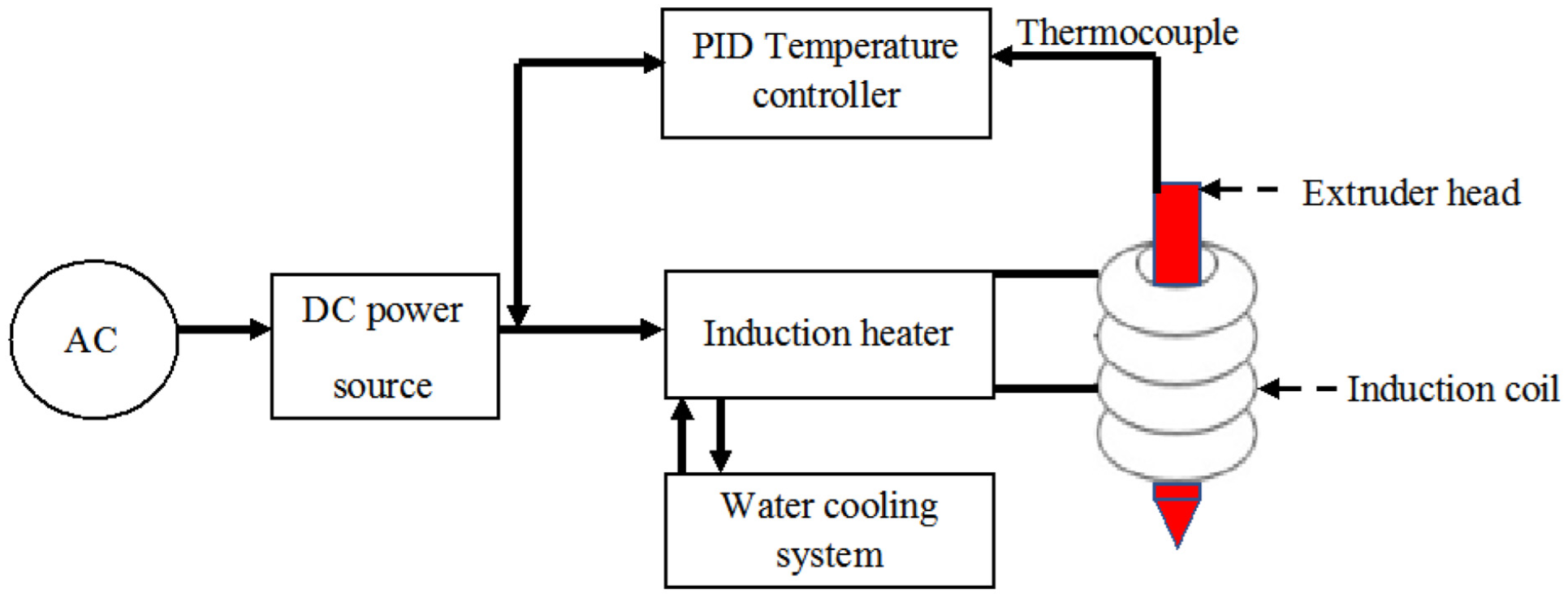
Block diagram of temperature control using PID in IH system.
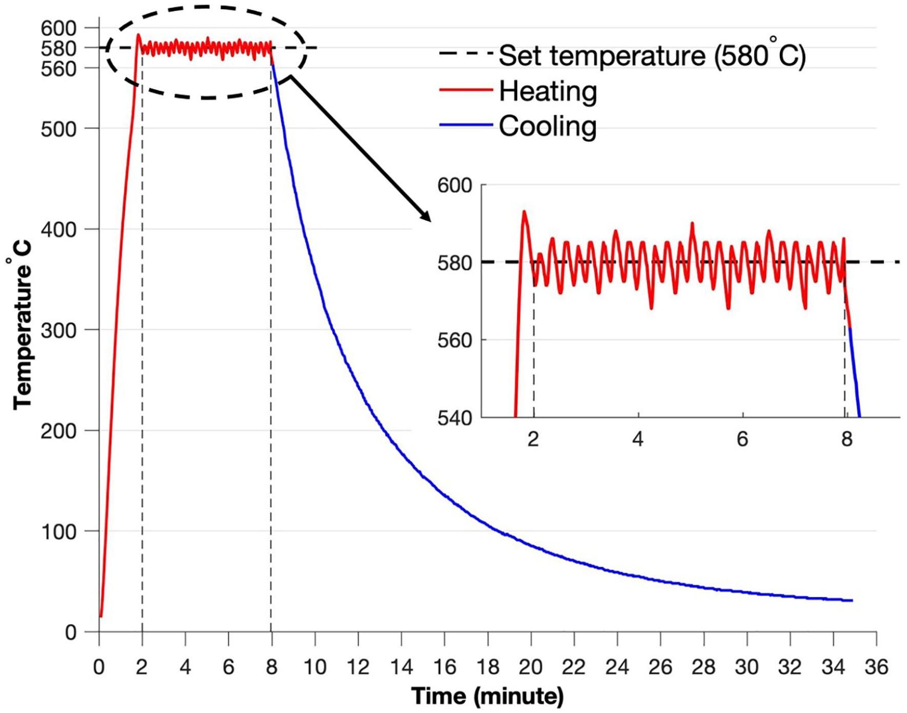
Extruder temperature profile with temperature control.
Experimental testing
The developed experimental setup is tested in order to see the capability of the extruder for the AM of metallic parts. The experiments have been performed to melt the metal filament of diameter 1.6 mm, through the induction heated extruder. Al alloy has been selected as raw material for initial testing purposes, due to its easy availability in the form of the filament. The initial extruder temperature has been set above the solidus temperature of Al alloy, which is 580° C. A filament feeding rate of 120 mm/min is chosen for this study. The reason for choosing the particular feed rate is due to the fact that the semi-solid processing of Al requires the transformation of Al wire in solid form to semi solidus state within the extruder. This transformation requires time, therefore, from extruder geometrical consideration and pilot experimentations, selection of feeding rate is made. Al filament is continuously fed to the extruder, where it is liquified within and extruded out in the molten metal drop form from the extruder tip, as shown in Figure 11(a). The molten metal drop size keeps on increasing with continuous feeding of the filament, as shown in Figure 11(b). After the sufficient increase in the drop size of molten material, it is detached from the extruder tip and falls on the substrate, the reason being the cohesive force of molten metal is less than the force of molten metal’s own weight, as shown in Figure 11(c). During the extrusion, the semi-solid state is held isothermally. When this semi-solid metal is extruded, the liquid and solid particles in the extruder were pushed towards extruder tip by the incoming feed material to form a drop. Then, due to the balance between the cohesive and surface tension forces, it tries to retain a minimum volume in the form of a droplet. Hence, the experimental result shows that the induction heated extruder head is capable of rapid melting the aluminium alloy within the extruder and continuously extrude out the molten metal from extruder tip.
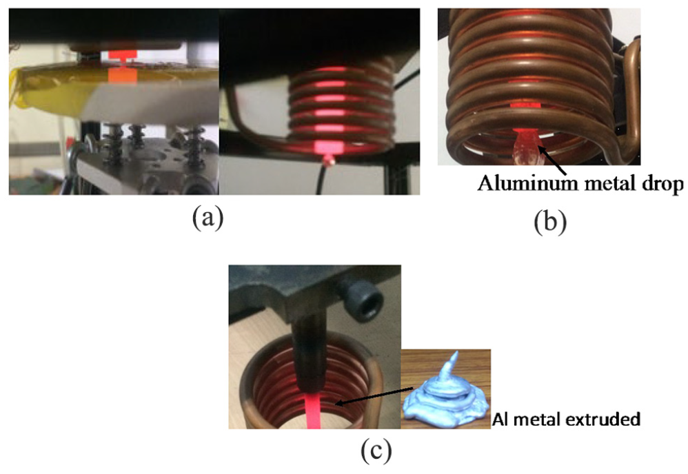
(a) Extrusion of aluminium metal and drop formation, (b) continuous metal drop formation at extruder tip, and (c) stacking the molten aluminium metal on the substrate.
Issues and challenge
Various issues and challenges are observed during the preliminary experiments such as filament breakage, material blockage, and oxide layer formation in the extrusion of material. In order to deal with these issues, some trial experiments are performed to overcome them by some modifications in the extruder head design.
Filament breaking is one of the primary issues occurring at the start of experimentation. Aluminium filament suffers wire buckling or cut-off at the entrance of extruder, as shown in Figure 12(a). The filament breakage might have occurred due to undesired and uncontrolled heat transfer from extruder towards the filament entrance. At the entrance of extruder, aluminium filament grasps heat from the extruder and becomes very soft, which results in buckling and subsequent breakage of the filament. This problem was resolved by incorporating a cooling unit at the entrance of extruder head to control heat transfer to the material at the entrance of extruder. Therefore, a water-based cooling system was developed to maintain the temperature at the entrance of the extruder head, as shown in Figure 12(b). The cooling unit is a hollow cylindrical shape of aluminium alloy, which has a single inlet and an outlet port for the supply of water. To check the temperature at entrance of the extruder, a thermocouple is inserted at the junction of the cooling unit and the extruder (Figure 12(b)). Later, the experiments are conducted with and without supply of water. The temperature of extruder head entrance was 416° C without the water supply, and with the water supply, the measured temperature was 243° C. Hence, it is seen that the cooling unit is capable of reducing the temperature at the extruder entrance, thereby preventing filament buckling.
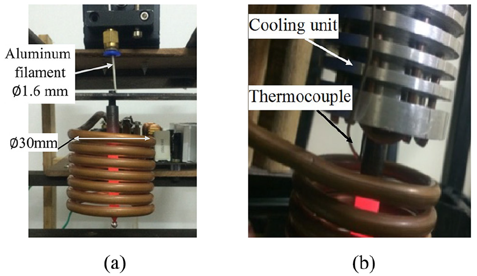
(a) Filament breakage and (b) cooling unit with the thermocouple.
The material blockage is another issue that arises during the extrusion of metal material. For uniform heating of extruder, it is required that the extruder should be exactly at the centre of the induction coil. However, due to inaccuracy in fabrication, extruder may misalign with the induction coil centre, which results in improper melting of the metal filament inside the extruder head due to uneven distribution of electromagnetic flux to the extruder. Therefore, solid metal particles are stuck in the extruder nozzle tip, which blocks the extrusion of material. This problem was resolved by the proper alignment of the centre of extruder head to the induction coil.
Discussion and conclusion
This article presents the feasibility study of the IH system for AM. The main objective of the article is to introduce a rapid heating technique to transform the solid metal filament into a melt form and further extrude out the molten material using the extrusion technique. This article also discusses various issues, while developing the extruder system based on the induction principle, such as suitable material selection for extruder, and temperature control. A pilot study has been conducted in order to analyse the suitability of the developed system to melt aluminium alloy ER4043. The analysis of the result shows that the extruder of cast iron material has the capability to operate efficiently up to 1000° C. In order to control and maintain the temperature of the extruder at a particular value, a PID controller and a thermocouple have been used. As a result, the controller maintained the temperature of the extruder above the solidus temperature of input material, required to convert metal into the semi-molten form. The semi-molten metal material extrudes in the form of drops and deposits successfully on the substrate. The process has been successfully implemented to extrude the metal. However, there are still many challenges to be overcome to achieve successive material deposition in layer form. The scope of this study is limited to the deposition of nonferrous metallic alloys like aluminium series alloys, due to the design consideration of the extruder head.
Footnotes
Declaration of conflicting interests
The author(s) declared no potential conflicts of interest with respect to the research, authorship, and/or publication of this article.
Funding
The author(s) disclosed receipt of the following financial support for the research, authorship, and/or publication of this article: The author would like to thank DST/TDT/AMT, India, for providing financial support. This work has been carried out under the DST/TDT/AMT sponsored project ‘Development of induction conduction based material deposition system for metal additive manufacturing’ (DST/TDT/AMT/2017/119/G).