
Abstract
Oscillating water column wave energy harvesting system uses pneumatic power to run a turbine and generate power. Both reaction (mainly Wells turbine) and impulse type turbines are tested in oscillating water column system and the performances are investigated. Reaction turbines are easy to install, and the operating range is narrow and possesses higher peak efficiency. On the contrary, impulse turbines have the wider operating range and lower peak efficiency. Some of the key parameters for Wells turbine are solidity, tip clearance, and the hub-to-tip ratio. Significant performance improvement is possible by redesigning the turbines using optimization techniques. Till date, surrogate modeling and an automated optimization library OPAL are commonly used in optimization of oscillating water column air turbines. In this article, various types of oscillating water column turbines are reviewed, and optimization techniques applied to such turbines are discussed. The Wells turbine with guide vane has the maximum efficiency, whereas the axial-impulse turbine with pitch-controlled guide vane has the widest operating range. Turbines with optimized geometry have better overall performance than other turbines.
Introduction
The ocean waves are a vast source of energy; harnessing this energy in a judicious way can become the main source of electrical energy supply for countries with long shorelines. Yoshio Masuda (1925–2009), a pioneer in wave energy technology development, studied the wave energy devices since 1940. Masuda developed navigation buoys installed with air turbine, which is later known as oscillating water column (OWC) (Masuda, 1986). Later, a large (80 m × 12 m) barge, named Kaimei (Miyazaki and Masuda, 1975), was used to test the OWCs. During the same time, Salter (1974) tested a simple mechanism of vertical vane pivoted about a horizontal axis which can generate power using the oscillatory motion of ocean waves. Since then, researchers have developed several different types of wave energy converters and tested in the laboratory or real sea condition. Wave energy converters are categorized mainly based on location, size, and working principles (Drew et al., 2009; Falcão, 2010; Falnes, 2007; López et al., 2013; Sabzehgar and Moallem, 2009). One of the main issues of OWC is that it is not suitable for all coastal regions and requires very specific location characteristics. In spite of this, the OWCs have been studied most extensively and maximum numbers of prototypes are deployed into the sea.
The OWC, a pneumatic type wave energy device, can be used as a fixed or a floating type. The plants at Sakata port in Japan (Takahashi et al., 1992) and Vizhinjam, India (Ravindran et al., 1997) are examples of such plants. The energy conversion process in OWC plant (Figure 1) occurs in three phases. Initially, the oscillation of sea surface is converted to pressure energy in the air chamber and the air turbine converts the pressure energy into mechanical shaft power (this system is also known as power take off mechanism). Finally, the generator connected to the turbine converts the shaft power to usable electrical power.
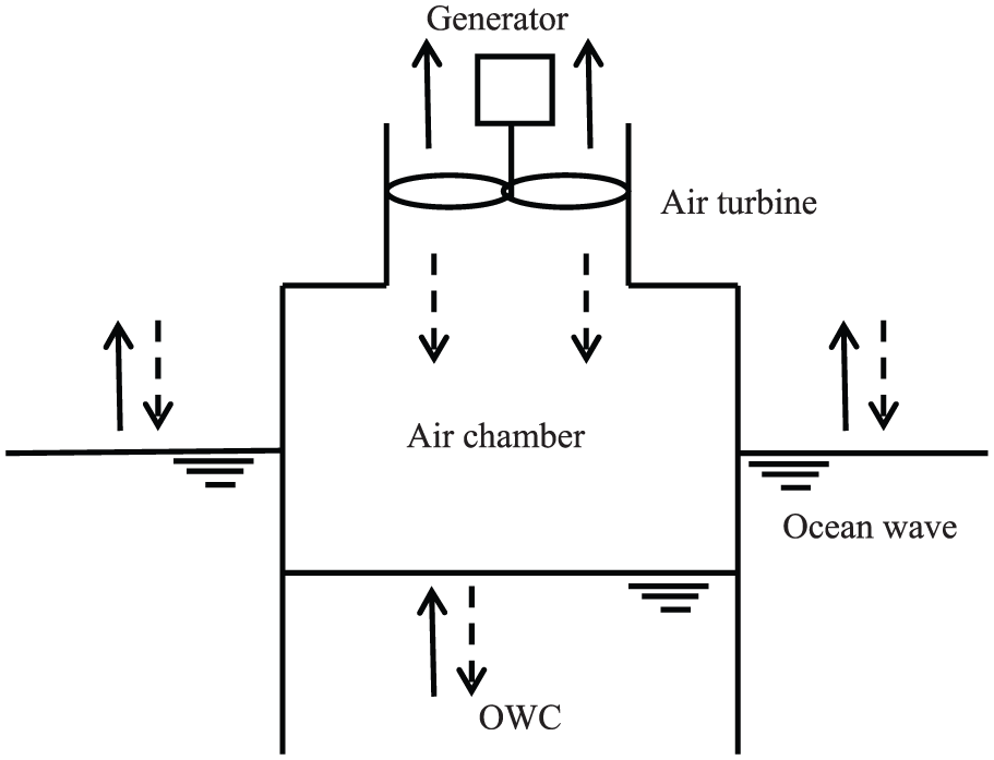
Schematic representation of OWC.
Most of the OWC systems for wave energy conversion used till date mainly relied on two basic types of air turbines: the Wells turbine and the impulse turbine. Unlike the conventional impulse turbine, the impulse air turbine for wave energy conversion is used with two rows of guide vanes on both sides of the rotor to make the turbine rotate in one direction regardless of incident airflow directions. However, the presence of guide vane on the downstream side of rotor introduces losses, which affect the turbine performance considerably (Thakker and Dhanasekaran, 2005). Figure 2 shows various turbines used in OWCs, which are discussed in the next section.
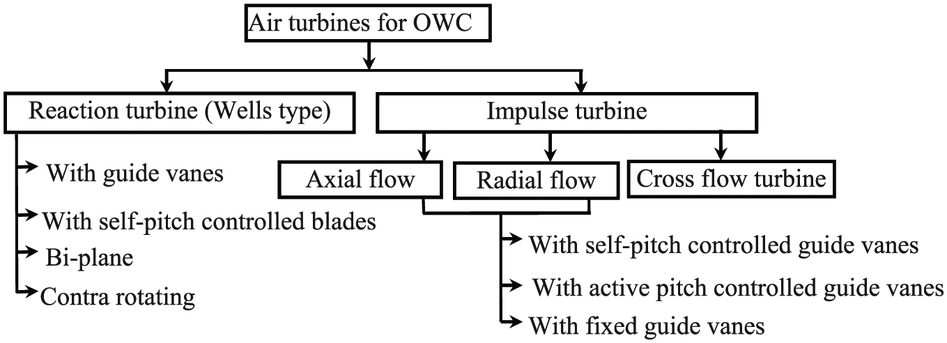
Classification of air turbines.
Some authors reviewed the articles on OWC and air turbines. Setoguchi et al. (2001a) presented the review of impulse turbines used for wave energy conversion. Setoguchi and Takao (2006) and Takao and Setoguchi (2012) compared different turbines including Wells and impulse turbines. Falcao and Henriques (2016) extensively reviewed air turbines including thermodynamics of air chamber and control algorithms applied to OWC turbines. However, these reviews did not discuss optimization techniques applied to OWC turbines.
Optimization works in the area of air turbines are new, and very few authors have applied optimization techniques to improve the turbine performance through systematic design optimization. This article discusses different turbine options along with the performance improvement achieved through optimization.
Turbine classification
Turbines are devices in which the rotor receives energy from the flowing fluid and convert this energy into mechanical energy. This mechanical energy is converted into electrical power using a generator. Based on the type of fluid, turbines are classified as steam, hydro, or air turbines. The power generated by the turbine is derived from equation (1). It is noticed that power developed is a function of pressure head and volume flow rate across the turbine

Based on the rationale of energy transfer inside the turbine, two main types of turbines exist: impulse turbines and reaction turbines. In the case of impulse turbines, the total pressure energy of the fluid is converted to kinetic energy before hitting the rotor blades, whereas in the case of reaction turbines, the pressure and kinetic energy both change as the water flow through the rotor blades.
The Euler turbo-machinery equation relates the torque of the turbine rotor T with the change in moment of momentum of the fluid across turbine rotor (Vavra, 1960)
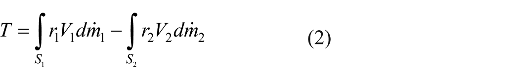
where S refers to the surface of revolution (subscript 1 refers to the inlet and 2 the outlet). Applying one-dimensional approximation, the equation becomes (Dixon, 1995)

where r and V are averaged over the inlet and outlet surfaces, S1 and S2, respectively. For any axial flow machine with mean radius

Equation (4) shows that a positive torque is obtained only when the tangential component of flow velocity at the inlet is greater than the outlet, that is,
Wells turbine
Wells turbine is an axial flow reaction turbine specifically used for wave energy extraction with the help of oscillating airflow. The turbine is made up of symmetric airfoil type blades placed around a central hub (Figure 3) and rotates in one direction irrespective of the direction of the airflow. It has a rotational speed limited by the blade tip velocity approaching toward the speed of sound. The turbine is coupled with the electrical generator and operates with or without guide vanes (Raghunathan et al., 1982).
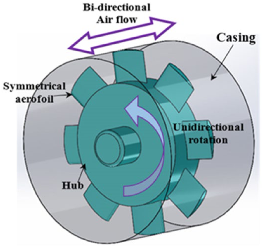
Schematic of a Wells turbine.
The Wells turbine works on the general aerodynamics theory of airfoil (Gato and Falcão, 1988; Raghunathan et al., 1994; Raghunathan and Tan, 1983). Blades are set at 90° stagger angle. The absolute velocity of air hits the blade axially and the tangential velocity of the blade acts in a direction parallel to the plane of rotation. The relative velocity W acting at an angle α (angle of attack) to the blade causes a lift force L perpendicular to the direction of W and a drag force D in the direction of W (Figure 4). This lift and drag force can be resolved in tangential and axial direction


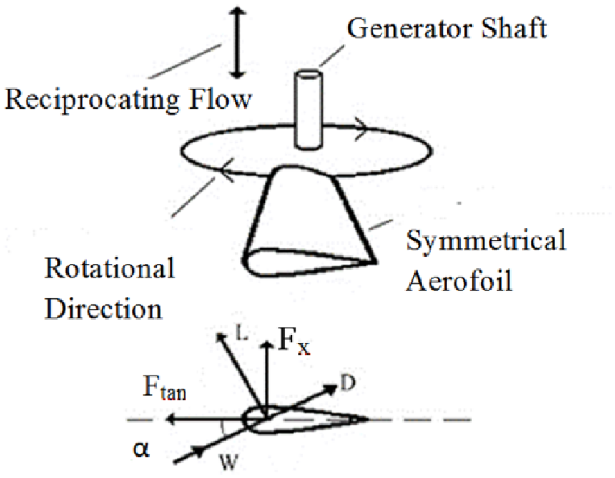
Principle of operation of Wells turbine (Cruz, 2008).
For any airflow direction, the direction of tangential force is always same. Therefore, the direction of the rotation of turbine always remains the same. For any real fluids, the lift and drag force on the airfoil increase up to a certain value of the angle of attack (α) beyond which the flow separates around the airfoil. The angle at which flow separates from the airfoil is known as the stall angle. Beyond the stall angle, the lift force decreases and drag force increases significantly. As a result, tangential force on the rotor decreases, leading to the decrease in efficiency. Thus, the angle of stall bounds the operating range of Wells turbine (Raghunathan, 1995a).
Another main disadvantage of wells turbine is poor starting characteristics and it is difficult to reach its operational speed (Inoue et al., 1986). This phenomenon of turbine failing to reach its operational speed is known as crawling (Raghunathan and Tan, 1982). Changing the hub-to-tip ratio and the solidity improves the starting characteristics of the turbine.
Parameters of Wells turbine
Some of the main geometric parameters that affect the performance of wells turbine are solidity, hub-to-tip ratio, aspect ratio, and tip clearance. Table 1 gives the analytical description of the parameters. The parameters are interrelated. Based on the analytical solution, Raghunathan (1995a) has given recommended values for these parameters, which are listed in Table 1. To achieve maximum efficiency and wide operating range, optimum values of these parameters are required. This is discussed in section “Optimization of air turbines.”
Parameters of Wells turbine.
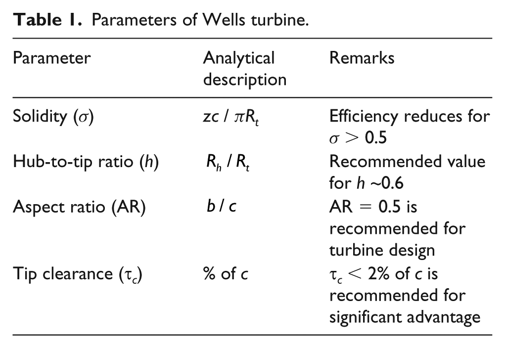
Solidity is a way to calculate the blockage of airflow within the Wells turbine and measures the mutual interaction between the blades (Cruz, 2008; Raghunathan and Tan, 1983). With increasing solidity, blades become too close to each other. As a result, blades interact with the boundary layer near hub leading to boundary layer separation on the surface of the hub as well as on the blade surface near the hub (Gato et al., 1996; Watterson and Raghunathan, 1998). This creates end wall losses in the hub region. The effect of the hub-to-tip ratio is well studied (Raghunathan, 1995a), and the results indicate that efficiency decreases with the increasing hub-to-tip ratio.
Effects of guide vane angle and tip clearance (Dhanasekaran and Govardhan, 2005; Setoguchi et al., 2003; Taha et al., 2011) are important parameters for the performance of Wells turbine. Halder and Samad (2014) carried out numerical analysis to study the effect of guide vane angle on the performance of Wells turbine. For a particular symmetrical blade profile (NACA 0021) under steady-state condition, guide vane angle of 11.8° gives maximum efficiency. The efficiency is maximum for a tip clearance of 1% (Halder and Samad, 2015a). In addition, a circumferential groove (Halder et al., 2015b) with a groove depth of 3% chord length produces the highest power and widest operating range. Also for a particular operating point, 26% improvement in efficiency is achieved using this method (Halder et al., 2015b).
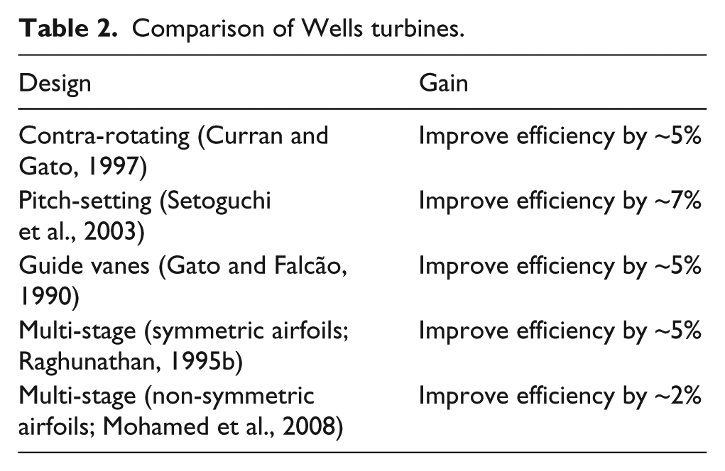
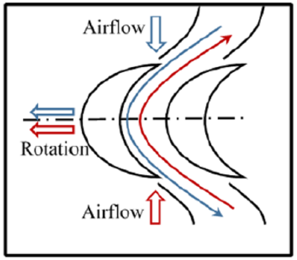
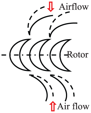
Guide vanes, self-pitch control blades, biplane turbines, blade sweep, and duct geometry improve the performance and starting characteristics of the turbine (Gato and Falcão, 1990; Halder et al., 2015a; Kim et al., 2002; Setoguchi et al., 1998, 2001b; Shaaban and Abdel Hafiz, 2012; Takao et al., 2000). Two stages of blades (Figure 5), both with symmetric and asymmetric blade profile, were studied (Gato and Curran, 1996). In a contra-rotating turbine, both the rows of blade rotate in different directions (Figure 6). LIMPET used two contra-rotating turbines each connected to a 250 kW induction generator producing 500 kW maximum power output (Boake et al., 2002). One of the recent developments in Wells turbine is to use three-dimensional (3D) blade where the blade thickness varies in the radial direction (Figure 7). Takao et al. (2015) used NACA0015 and NACA0025 at hub and tip, respectively, to create a new 3D blade geometry. Halder and Samad (2015b) studied a blade profile created by combining NACA0015 and NACA0024 at the hub and tip section, respectively. Results indicated that the 3D blade has better performance in terms of peak efficiency. All the modifications discussed here are summarized in Table 2 for better understanding.
Two-stage (biplane) Wells turbine (Mohamed, 2011).
Contra-rotating Wells turbine (Mohamed, 2011).
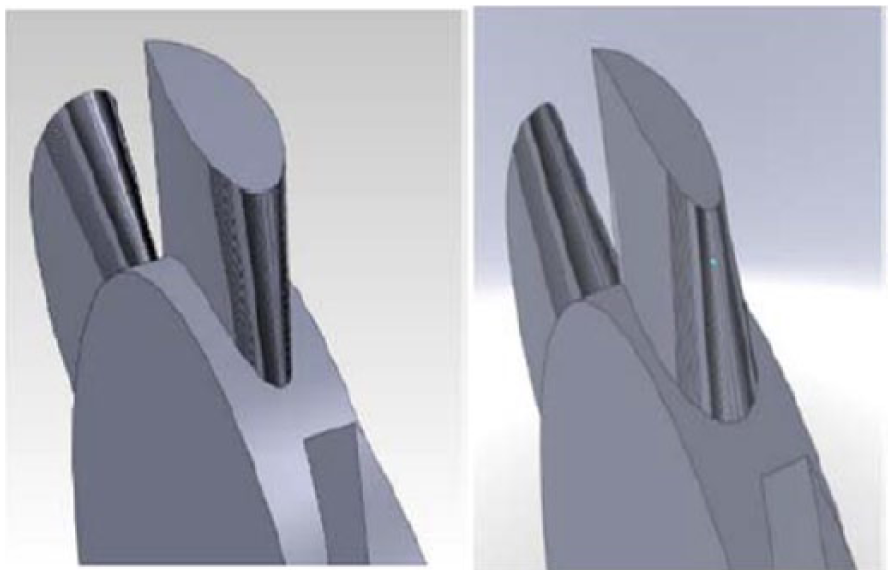
Three-dimensional blade (Takao et al., 2015).
Comparison of Wells turbines.
Impulse turbine
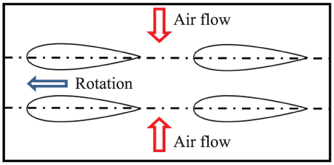
The main difference between a reaction turbine and an impulse turbine is the way energy transfer occurs in the rotor. Impulse turbines are classified based on the direction of airflow through it: axial and radial. An impulse turbine can be made bidirectional flow turbine using guide vanes on both sides of the rotor. Airflow deflected by the guide vanes hits the rotor blade and gives “impulse” to the turbine. Because of the symmetrical nature of the guide vanes and rotor blade, the turbine always rotates in the same direction irrespective of the direction of airflow (Figure 8). This type of turbine is also known as a self-rectifying turbine. Furthermore, guide vanes can be classified as fixed, self-pitch-controlled, and link mechanism type.
Schematic diagram of flow through impulse turbine.
Although Wells turbine was the first choice to be used in OWCs because of its self-rectifying characteristics, it has many inherent disadvantages (Setoguchi et al., 2001a). Axial turbines are very popular for its simplicity and ease of operation in both unidirectional and bidirectional flows. However, the axial turbines produce high axial thrust which causes fatigue failure of bearings. Radial turbines produce less axial thrust compared to the axial turbine. In addition, the torque obtained by the radial turbine is high due to the radial configuration. In spite of high damping produced by the radial turbine, it is favorable because of its toughness and low maintenance cost (Setoguchi et al., 2000, 2002).
Axial impulse turbines
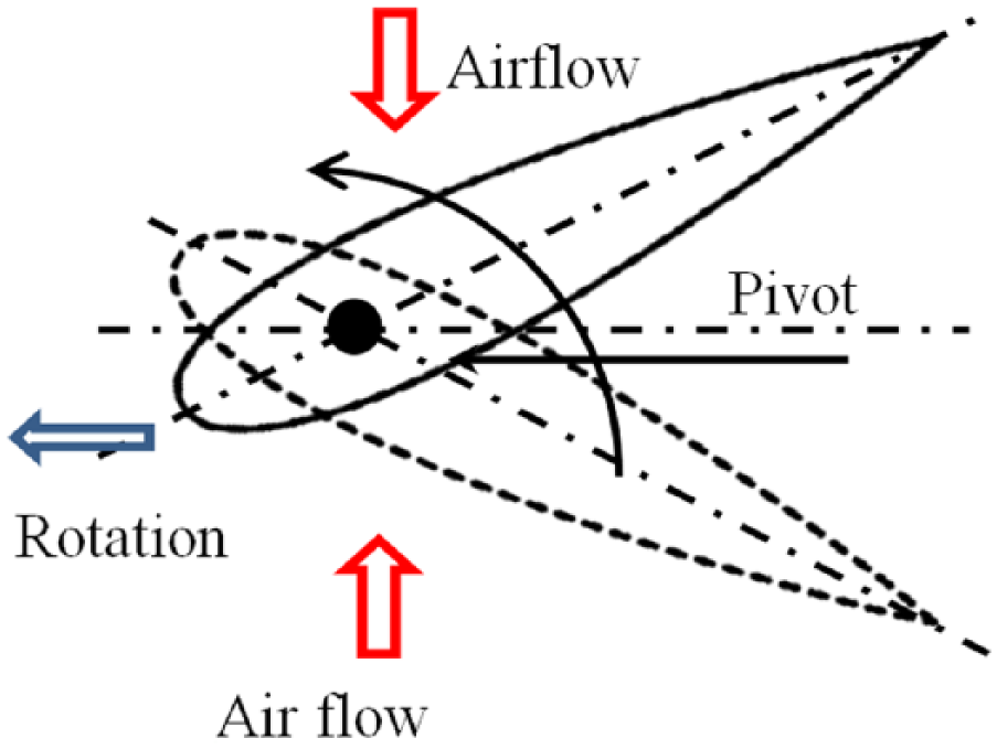
Turbine with self-pitch-controlled guide vane
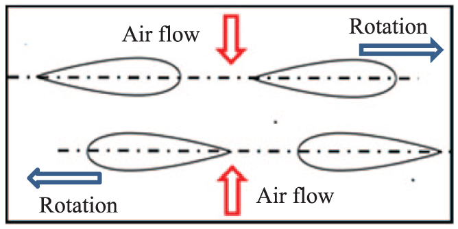
The most popular alternative of the Wells turbine is the axial flow impulse turbine. The geometry of the rotor blades of axial flow impulse air turbine is just a modified version of conventional steam turbine of impulse type. In the case of self-pitching guide vane, two sets of guide vane on either side of the rotor are pivoted and change direction according to the direction of flow with the help of aerodynamic moment. Guide vanes are also capable of changing orientation in the right direction for efficient operation (Figure 9). The upstream guide vanes act as a nozzle and downstream guide vanes act as a diffuser (Setoguchi et al., 2001a). Inoue et al. (1996, 2000) compared the analytical and experimental result of an impulse turbine with self-pitch-controlled guide vane. This is done for both steady flow and oscillating flow conditions. As part of the Indian wave energy program, an impulse turbine with self-pitch-controlled guide vane is tested in the OWC-based wave energy plant at Vizhinjam (Santhakumar et al., 1998). Later, Setoguchi et al. (2004) carried out numerical analysis of this type of turbine to understand the performance with respect to various parameters such as Reynolds number and hub-to-tip ratio. From the idea of self-pitch-controlled guide vanes, Liu et al. (2016) developed and studied an impulse turbine with pitch-controlled blade. For the particular turbine studied, results show that the rotor blade pitch angle of 5° gives the best efficiency in a wave cycle. The turbine shows better performance than zero pitch angle blades. Similar to the self-pitch-controlled guide vanes in impulse turbine, Wells turbine can be used with self-pitch-controlled blades, where the symmetrical airfoil blades change the stagger angles by themselves to obtain higher torque (Figure 10; Setoguchi et al., 1997).
Axial turbine with self-pitch-controlled guide vane (Setoguchi et al., 1993).
Air-turbine with self-pitch-controlled blade (Setoguchi et al., 1997).
Turbine with fixed guide vane
Although the turbine with self-pitch-controlled guide vane operates with higher efficiency over a wide range of flow rates, it has certain inherent disadvantages because of the variable geometry design. It requires a powerful configuration to withstand the self-pitching mechanism for a substantial number of oscillation cycles per day. In addition, the turbine consists of a large number of moving parts, which leads to higher operating and maintenance cost. Fixed guide vane can mitigate all these problems with the cost of overall performance of the turbine. Kim et al. (2000) carried out two-dimensional numerical analysis based on full Reynolds-averaged Navier–Stokes equation to investigate the internal flow behavior of an impulse turbine with fixed guide vanes. Results from other numerical analyses indicate that maximum efficiency occurs for a guide vane angle of 30° (Maeda et al., 1999, 2001). The two-dimensional analysis shows that significant total pressure drop occurs in the downstream guide vanes, which leads to the lower performance of the turbine. Thakker and Dhanasekaran (2005) carried out a computational fluid dynamics (CFD) analysis on 3D guide vanes using the well-known vortex theory. Experimental results indicate that the efficiency can be improved by an average of 4.5% points by incorporating 3D guide vanes (Thakker et al., 2005). Numerical analysis of flow through impulse turbine (Badhurshah et al., 2014) shows that the flow separation occurs in the tip region near trailing edge of the blade. However, with the increase in rotational speed, the separation points shifts toward the hub. A study on rotor solidity ratio recommends solidity of 0.63 to be used for best performance (Cui and Liu, 2014). The comparison of the starting characteristics with Wells turbine shows that both the types of impulse turbines accelerate faster than the Wells turbine (Figure 11).
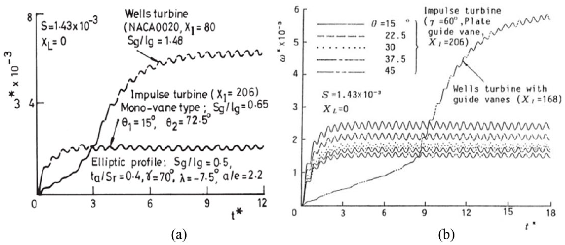
Comparison of starting characteristics (Setoguchi et al., 2001a): (a) impulse turbine with self-pitching guide vane and Wells turbine and (b) impulse turbine with fixed guide vane and Wells turbine.
Radial impulse turbines
Self-rectifying radial-flow impulse turbines are studied to investigate the suitability to use as air turbine for wave energy plants. Radial turbine with active pitch-controlled guide vanes (Figure 12) has been studied thoroughly by model test under steady sinusoidal flow. The steady sinusoidal flow is expressed as

where U is the inlet air velocity, f is the frequency of airflow, and λ is the time step.
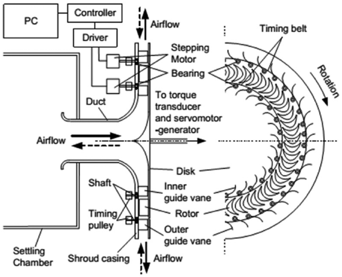
Radial turbine with pitch control guide vane (Takao et al., 2005).
The characteristic of internal flow behavior is clarified with the help of such tests. In addition, results show that the performance of this turbine is much superior compared to the conventional fixed guide vanes radial turbine (Takao et al., 2005). Experimental tests were carried out on a bi-radial impulse turbine under unidirectional steady flow condition (Gato et al., 2012). As wave energy turbines are installed inside a cylindrical configuration, the flow behavior near the tip of the blade and guide vanes is different from conventional turbines. Results show that the turbine maximum efficiency reduces by up to 8% if the tip clearance changes from 0% to 4% of the blade span (Pereiras et al., 2011).
A new concept of twin impulse turbine was proposed and model tested by Jayashankar et al. (2009) and Mala et al. (2011). The experiment results show considerable improvement in operating range. In addition, the wave to wire efficiency crosses 50% with this specification. Thakker et al. (2009) provided a chart for selection of impulse turbine for wave energy extraction. The chart is based on experimental data. For example, it can be seen that for a rated power of 400 kW, the recommended rotor diameter from the chart would be 1.6 m.
Wells turbine versus impulse turbine
One of the main disadvantages of impulse turbine is the aerodynamic loss. This happens due to the large incidence angle of airflow near the downstream row of guide vanes (Karthikeyan et al., 2013); this is inevitable as it is required for the symmetry of the guide vanes. A comparison of both the turbines indicates that the impulse turbine has a wider operating range than the Wells turbine. However, it comes at a cost of peak efficiency; the peak efficiency of impulse turbine hardly exceeds 50% (Figure 13). For Wells turbine, the peak efficiency drops sharply when the stall occurs at a higher flow rate. To reduce the losses, variable geometry of guide vanes is proposed, which is discussed in the previous section. A comparison of efficiency with different non-dimensional flow coefficient for the two types of turbines is shown in Figure 13. The two-dimensional flow analysis by Falcão and Gato (2012) indicates that the change in Reynolds number has more impact on Wells turbine efficiency compared to the impulse turbine efficiency.
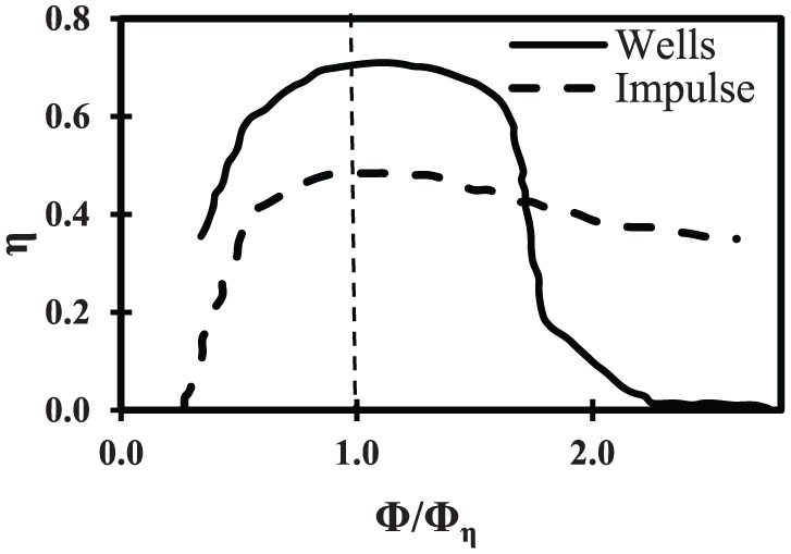
Comparison of efficiency between Wells turbine and impulse turbine for different flow coefficients, Φ η represents peak efficiency conditions (Setoguchi et al., 1992).
Presently, there are a number of wave energy plants operating on the OWC technology. A list of the types of turbines being used and respective countries is mentioned in Table 3. The list is not exhaustive, as there are few other wave energy plants, which are in developing stage. It can be seen that most of the prototypes and actual plants have used Wells turbine for operation.
OWC plants with turbines.
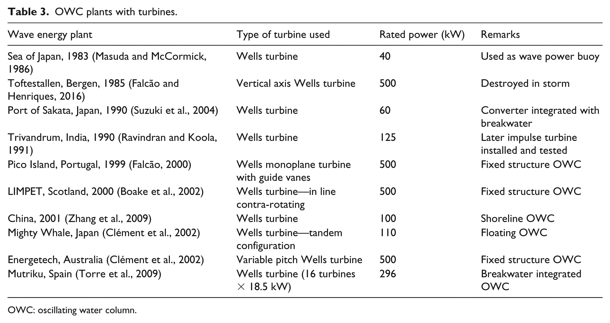
OWC: oscillating water column.
Optimization of air turbines
Optimization is a mathematical procedure aimed at finding the best solution among the whole set by efficient quantitative and qualitative methods. This section presents literature that tries to understand the performance and behavior of various types of turbines with optimized configurations. Optimization of the full system using modern computational methods can bring significant improvement in performance.
Optimization techniques are commonly used in turbomachines and aerospace systems to improve performance. Application of optimization is seen in wind turbines for performance improvement. However, literature related to optimization of wave energy system is limited. Unlike trial and error method, optimization here refers to numerical optimization using different algorithms. In the last decade, few authors have come up with the optimized geometry of OWC air turbines that shows better performance compared to conventional turbines. This section gives a detailed review of optimization methods used in OWC air turbines.
Optimization approaches are classified into traditional (direct or gradient based) and heuristic methods. Heuristic methods are favored in engineering optimization problems due to its capability of finding the global optima in less computational time. Authors worked on optimization of air turbines using two main types of optimization techniques: surrogate modeling and an automated optimization algorithm, OPtimization ALgorithm (OPAL). Surrogate model is an approximate model developed from hi-fidelity computational models such as CFD. On the other hand, OPAL is an optimization library that couples the computer-aided design (CAD) model with the CFD code. Parameters of wave energy turbines are interrelated. A multi-variable multi-objective optimization (MOO) is required to arrive at an optimized geometry for best performance.
Badhurshah and Samad (2015) carried out multiple surrogate–assisted genetic algorithm–based MOO on an impulse turbine to enhance the performance. The design variables were number of rotor blade and guide vanes and the objectives were the minimization of pressure drop and the maximization of shaft power of the turbine. Response surface approximation, neural network, kriging, and a weighted-average surrogate (WAS) were used to generate population for the MOO procedure and pareto optimal fronts (PoF) of the objectives were produced. The efficiency, which is a function of the both the objectives, is increased by ~11% through this investigation (Figure 14). Another study by the same author (Badhurshah and Samad, 2014) on the optimization of an impulse turbine shows that relative efficiency can be improved by approximately 13% over the full range of the flow coefficient (Figure 15).
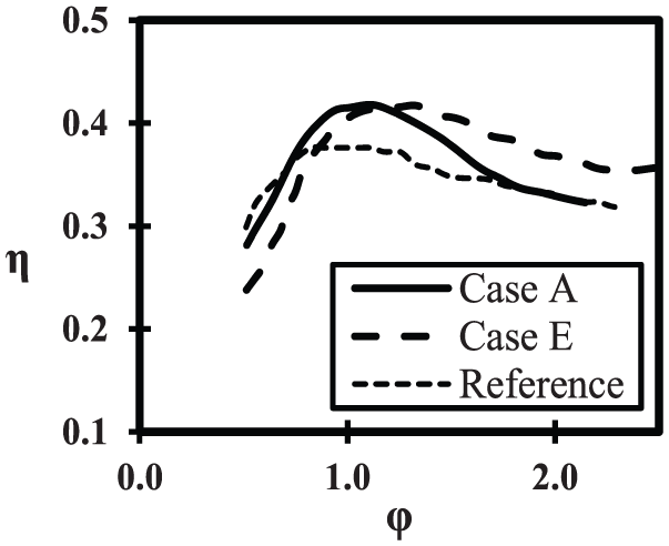
Comparison of efficiency between reference and different optimized cases (Badhurshah and Samad, 2015).
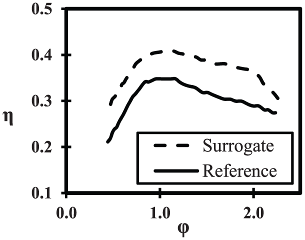
Comparison of efficiency between reference and surrogate predicted model (Badhurshah and Samad, 2014).
Mohamed (2011) developed an automated optimization algorithm, where a system can be optimized using a genetic algorithm and performance evaluation by CFD technique. The optimization of the airfoil shape (Figure 16) leads to a relative gain of 11.3% in power output and 1% increase in overall efficiency throughout the full operating range (Mohamed et al., 2011). The same algorithm applied to non-symmetric airfoil blades and self-pitch control blades (Mohamed and Shaaban, 2014) shows significant improvement in performance of the turbine.
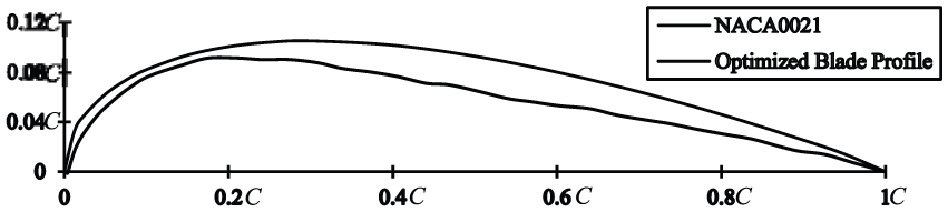
Comparison of NACA0021 profile and optimized blade profile (Mohamed et al., 2011).
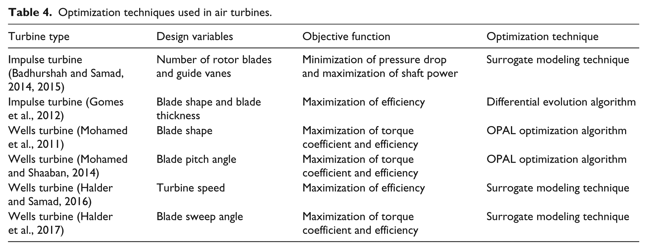
Gomes et al. (2012) developed a two-step optimization method for two-dimensional blade section of an axial flow impulse turbine. A 3D geometry is obtained by stacking two-dimensional optimized sections in spanwise direction. A CFD analysis of initial design and the optimized design shows almost 5% improvement in efficiency. Halder and Samad (2016) determined optimal turbine speed for Wells turbine using surrogate-based optimization technique. A multiple surrogate–based approach is used to determine optimal turbine speed for different flow velocities. The analysis shows that a turbine with 3% groove depth gives better performance than a turbine with 1% tip clearance. Another study by Halder et al. (2017) used the surrogate modeling technique to optimize the blade sweep angle. The optimized turbine blade has backward sweep at mid-section and forward sweep at tip section. For the optimized geometry, torque coefficient increased by 28.28% and the operating range increases by 18.18%. It is clearly visible that optimization techniques have been used successfully to improve the performance of air turbines. A complete 3D optimization may be complicated and numerically expensive; however, it can give more accurate result than the previous ones. All the design modifications done using optimization are summarized in Table 4.
Optimization techniques used in air turbines.
Conclusion
A comprehensive review of OWC air turbines (Wells and impulse turbines) is reported in this article. Previous review articles on OWC air turbines discuss different design modifications and comparison with various turbines. Unlike previous review papers, this article concentrates on the optimization of air turbines used in OWCs along with a discussion on parameters of the air turbine. It is expected that this article will help researchers in OWC optimization to acquaint with the present state of the art. Some of the main findings of this article are summarized here:
Among the various parameters affecting the performance of Wells turbine, blade solidity and tip clearance are the most important. Small tip clearance increases efficiency by reducing leakage loss, whereas a large tip clearance postpones stall and provides wider operating range. The performance of Wells turbine is limited by stall, and in varying sea condition, a wide operating range is preferable over the efficiency of turbine.
Impulse turbines required guide vanes to operate on bidirectional airflow. Variable pitch guide vanes have better performance than fixed guide vanes in terms of wider operating range and higher efficiency.
Radial turbines are complex in operation and maintenance, whereas the axial turbines are simple in operation and possess higher peak efficiency than the radial turbines.
A comparison between Wells and impulse turbine shows that Wells turbine with guide vane provides maximum peak efficiency, whereas axial-impulse turbine with variable pitch guide vanes results in maximum operating range.
Optimization of OWC turbines is a relatively new area of research. Heuristic methods are preferred in numerical methods for air turbine optimization.
Optimized blade shape for both Wells and impulse turbines gives better performance than reference turbine.
For impulse turbine, optimization is carried out for number of blades and guide vanes; for Wells turbine, optimization is done for blade pitch angle, blade sweep angle, and turbine speed. Optimized geometry shows overall performance improvement in all the cases.
Most of the works on air turbine considered the turbine geometry separately. However, the performance of air turbine is influenced greatly by the hydrodynamics of the OWC. As a future research, it is suggested to analyze the performance of OWC along with the air turbines.
Footnotes
Appendix 1
Declaration of conflicting interests
The author(s) declared no potential conflicts of interest with respect to the research, authorship, and/or publication of this article.
Funding
The author(s) received no financial support for the research, authorship, and/or publication of this article.