
Abstract
The behaviour of arrays of 12 heaving point absorbers in concentric arrangements is numerically assessed in a frequency domain model. The floaters are attached to a central cylindrical bottom-mounted structure. Each point absorber is restricted to the heave mode and is assumed to have its own linear power take-off system consisting of an external damping coefficient enabling power extraction and a supplementary mass coefficient tuning the point absorber to the incoming waves. The external damping and supplementary mass coefficients are optimized to maximize the power absorption by each floater in the array, with a restriction on the total control force that can be applied on the floaters. Various concentric arrangements with different radii and number of concentric circles are analysed to determine the most efficient among them. Moreover, the influence of the presence of a central bottom-mounted pillar and the effect of change in its dimension and shape on the power absorption are also studied.
Introduction
Wave energy conversion technologies can be classified in many different ways based on the working principle and location. Recent reviews on the existing wave energy converter (WEC) technologies can be found in Falcão (2010) and Guedes Soares et al. (2012, 2014). If the horizontal dimension of the device is much smaller than the typical wavelength of the ocean waves, the WEC is called a point absorber; otherwise, it is called a terminator or attenuator depending on if it is aligned normally or parallel to the prevailing wave direction. The point absorbers – floating or submerged – convert the vertical motion of ocean waves into linear or rotational motion for driving electrical generators by means of a power take-off (PTO) system. Point absorbers are very attractive because it can harness energy from a wavefront much larger than its own horizontal width (Budal and Falnes, 1975). However, the point absorbers must operate in arrays to produce considerable amounts of power from ocean waves. For multiple bodies, optimal control parameters are not only dependant on the incoming waves but also on the position and the behaviour of other floaters. Furthermore, optimal control theory has shown that multiple converters can exploit constructive interference to enhance power absorption by the WEC.
Several theoretical models have been developed by researchers in order to deal with waves and interacting bodies. Budal (1977) and Falnes (1980) adopted the point absorber approximation theory to derive the expressions for the maximum wave power which can be extracted by an array of point absorbers. The approximation relies on the assumption that the bodies are small compared to the incident wavelengths so that the wave scattering within the array can be neglected while calculating the interactions. A theory accounting more accurately for the wave-body interactions is the plane-wave approximation which is based on the assumption that bodies are widely spaced relative to the incident wavelengths, so that the radiated and circular scattered waves can be locally approximated by plane waves (McIver and Evans, 1984).
In this study, the performance of 12 heaving point absorbers arranged in concentric arrays is evaluated. The floaters are attached to a central cylindrical bottom-mounted platform by means of an arm. The concentric arrays differ in their radii and the number of circles into which the floaters are arranged. The effects of the dimension and the shape of the central pillar are also examined.
Concentric arrays
In order to analyse the performance of concentric array of point absorbers, the study is carried out for three concentric arrangements c1, c2 and c3, with floaters placed at different radii. The configuration c1 has an outer radius of 18 m and an inner radius of 9 m, the configuration c2 has an outer radius of 24 m and an inner radius of 12 m and the configuration c3 has an outer radius of 30 m and inner radius of 15 m. The configuration c2 is shown in Figure 1, for which most of the calculations are carried out in this article.
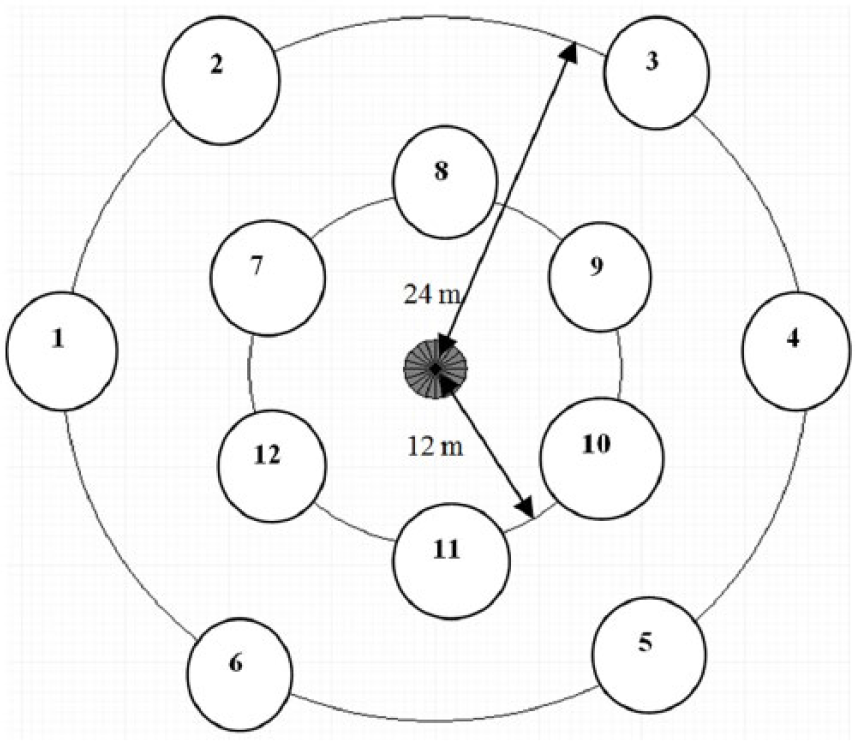
Concentric array of floaters for configuration c2.
The floaters in each configuration are placed in the same position relative to the central cylindrical platform, as shown in Figure 1. The floaters have been numbered 1–12 in all the arrays, which makes it easier to compare the performance of each floater in different arrangements. The floaters numbered 1–6 are placed on the outer circle, and the other six numbered 7–12 are placed on the inner circle. The floaters placed in the inner and outer radii are 60° apart from each other. Moreover, the floaters in the inner circle are placed 30° from the corresponding floaters on the outer circle. The results of these concentric arrays are compared with linear and grid arrangements as in Sinha et al. (2015) and Backer et al. (2009), respectively. From the previous study (Sinha et al., 2015), a cone-cylinder floater shape, with an apex angle of 90° and a diameter of 5 m extended by a cylindrical part of 0.5 m, is chosen to be used in all the concentric arrays.
The floaters are attached, by means of an arm, to a central cylindrical bottom-mounted platform as shown in Figure 2. This platform, with a radius of 5 m and height of 50 m, is mounted on the seabed. Furthermore, the radius of this cylindrical platform is varied to study its effect on the performance and power absorption by each floater. Moreover, the shape of the platform is also changed. The incoming waves propagate in the direction of positive x-axis as shown next to Figure 2. In Figure 1, the floaters numbered 1, 2, 7, 12 and 6 are the ones facing the incoming waves and will be referred like that in the further sections. The floaters numbered 3, 9, 10, 5 and 4 will be referred to as placed on the right side of the configuration.
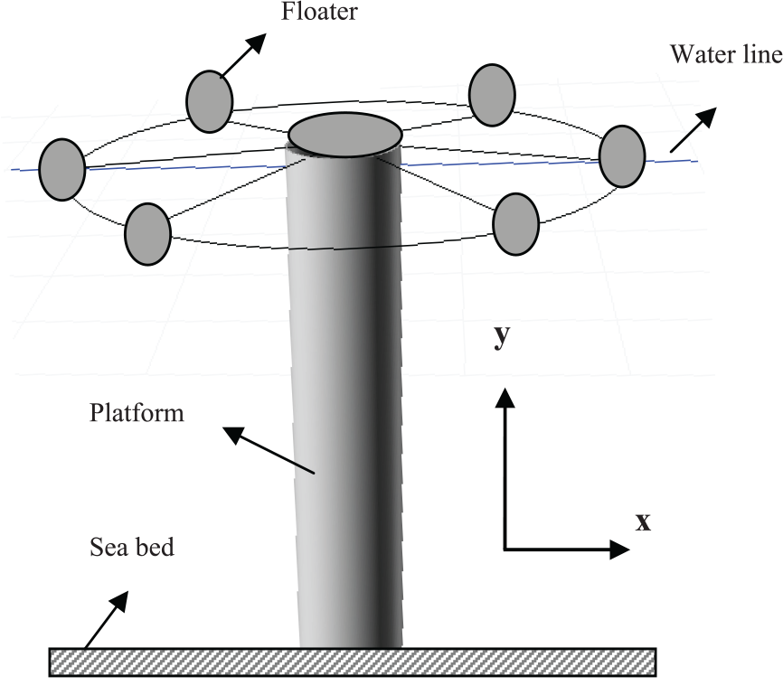
Bottom-mounted cylindrical platform connected with point absorbers.
Numerical modelling
Frequency domain modelling
The equation of motion of
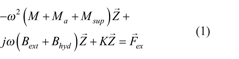
where
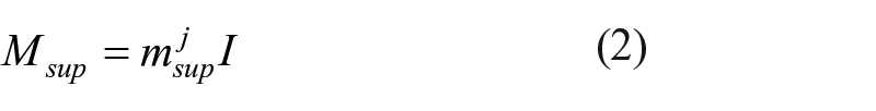
where
where
The average power absorption in regular waves is given by
where
where
The two control parameters
Force restriction
In some cases, the optimal control parameters for the maximum power absorption result in very large control forces. The tuning force, in particular, might become very large and can even be a multiple of the damping force. If this tuning force is to be delivered by the PTO, it might result in a very uneconomic design of the PTO system. For this reason, it is important to study the response of each floater in the case when the total control force is restricted. If the force spectrum is expressed as
and the significant amplitude of the force is defined as
Therefore, the significant amplitude of the damping and tuning forces for the
and
respectively.
Hence, the significant amplitude of the total force is given by
For the scope of this article, the total force which can be exerted on each floater is limited to a maximum significant value of 200 kN.
Wave climate
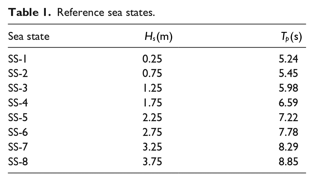
The calculations are performed for eight reference sea states of floater measurements as shown in Table 1. The majority of the calculations will be carried out for the sea state SS-5. The generated spectrum is based on the parameterized JONSWAP spectrum (Guedes Soares and Caires, 1995).
Reference sea states.
Results and discussion
The results for the average power extraction
Concentric arrays
The concentric arrangements of c1, c2 and c3 are analysed and the results are presented for each floater. It can be seen from Figure 3(a) that power absorbed by each floater varies for different arrangements. The floaters facing the incoming waves extract more power, performing the best for configuration c1 and the worst for configuration c3, that is, these floaters absorb less power
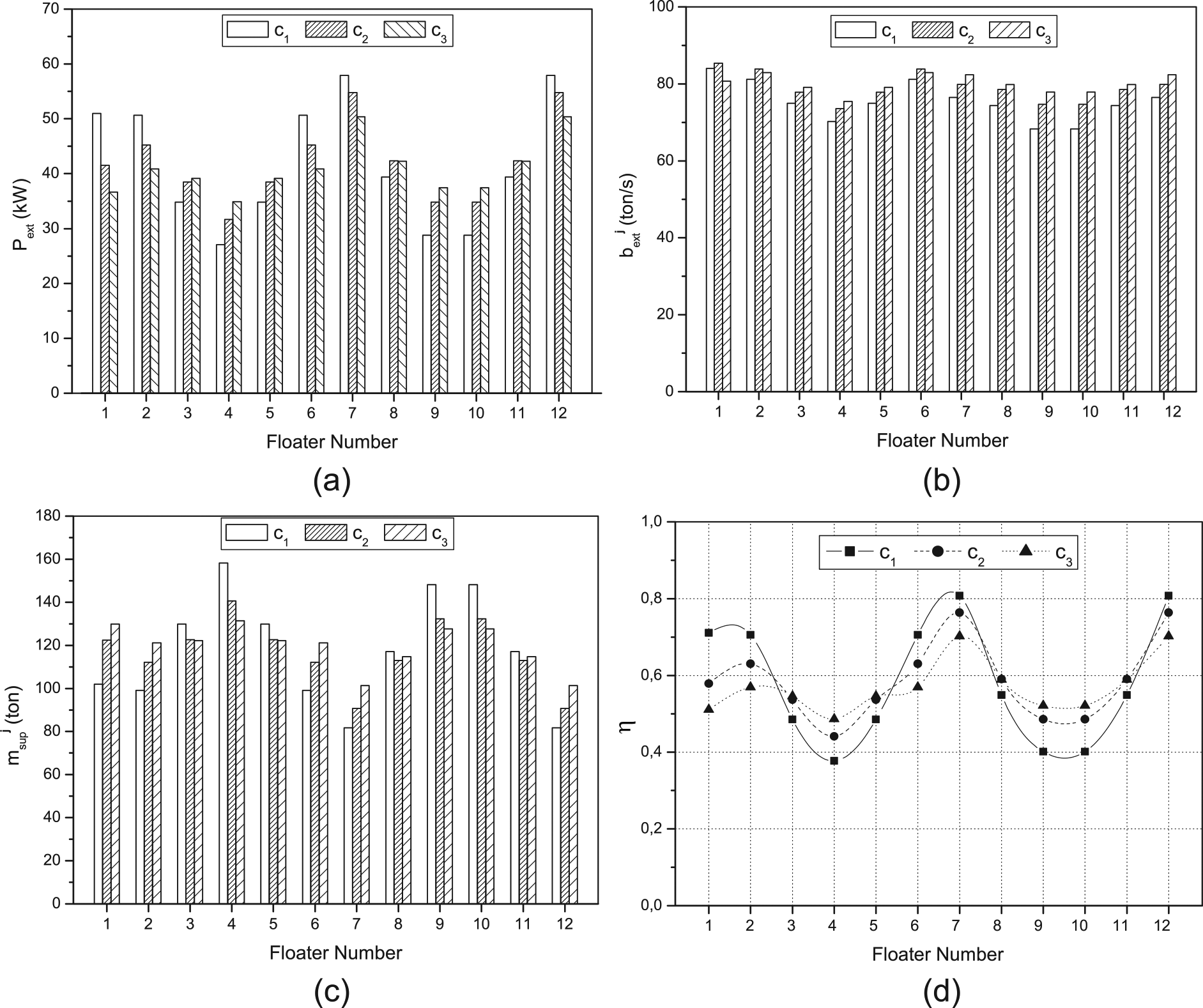
(a) Power extracted by each floater, (b) external damping coefficients for each floater, (c) supplementary mass coefficients for each floater and (d) absorption efficiency of each floater.
Figure 3(b) and (c) give the external damping and supplementary mass coefficients for each floater for configurations c1, c2 and c3. The control parameters do not vary much among the floaters, with configuration c3 having the most uniform values. The uniformity of control parameters among the floaters in an array is a good sign as it will be easier for the PTO mechanism to control the floater movements and in turn maximize the power absorption. The external damping coefficients
In linear and grid arrangements, the external damping and the supplementary mass coefficients vary a lot for different floaters (see Backer et al., 2009), unlike the uniform values for these concentric arrays of floaters. Therefore, it will be easier to control the floaters in concentric array and maximize the power absorption.
Figure 3(d) shows the efficiency of each floater for different concentric arrangements. As mentioned earlier, the floaters facing the incoming waves extract the most power and this value is the maximum for configuration c1. It is observed that these floaters are the most efficient. The floaters on the right side of the arrays are the most efficient for configuration c3. This graph helps us to understand which floater positions are the most efficient for different concentric arrangements and will be useful for effective floater positioning while designing the WEC.
In Table 2, the total power extracted by all the floaters in various concentric arrays is compared with that of linear and grid arrays as presented in Sinha et al. (2015) for SS-5. The results for the other sea states in the wave climate are presented later in this section. The concentric arrangement c2 performs the best, closely followed by c1 and then c3.
Total power absorption for different concentric arrangements.
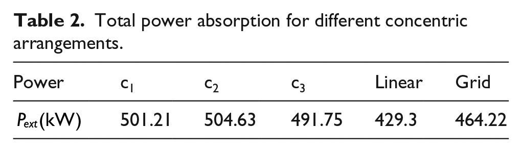
It is observed that with increase in the radius of the concentric configuration from c1 to c2, the power absorption increases, however, increasing the radius of the configuration again from c2 to c3, there is a decrease in power absorption. The configuration c3 has the least value among the three arrangements. Hence, the choice of radius for arranging the floaters into concentric circles is important while designing the WEC. The concentric array of floaters in configuration c2 extracts around 15% and 8% more power than linear and grid arrays, respectively, which is a notable improvement.
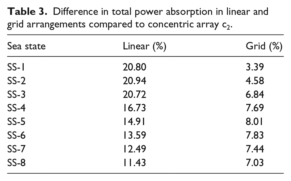
Table 3 shows the difference in percentage in the total amount of power extracted by 12 heaving point absorbers arranged in concentric arrays as compared to that in linear and grid arrays, for all the sea states in the wave climate. It can be seen that the concentric array c2 performs significantly better than the linear and grid arrays for all the sea states, absorbing on an average more than 15% and 7% power, respectively. Hence, we can say that the concentric array of floaters is much more efficient in terms of power extraction. Moreover, for a concentric array, it is easier to control the movement of the floaters, in addition to better accessibility and easier maintainability of WEC device.
Difference in total power absorption in linear and grid arrangements compared to concentric array c2.
Effect of platform dimensions
In this section, the radius of the cylindrical platform is changed to analyse its effect on the performance of the floaters for configuration c2. The calculations are performed for three values of platform radius – r = 3, 5 and 7 m.
It can be seen from Figure 4 that the floaters facing the incoming waves extract higher power
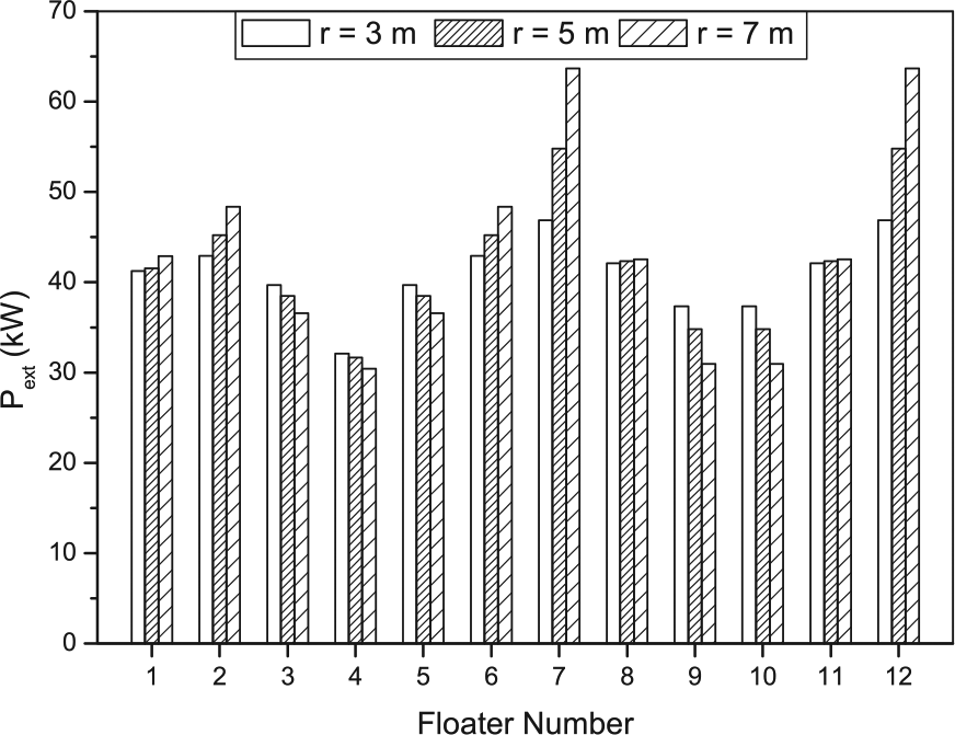
Power extracted by each floater with change in the pillar dimensions.
Table 4 shows the total power absorption with change in platform radius, for SS-5. The total power absorption increases with increase in the radius of the platform. The platform with radius 7 m extracts around 5% more power as compared to the one with a radius of 3 m. However, the difference is not large.
Total power absorption for different platform dimensions and shapes.
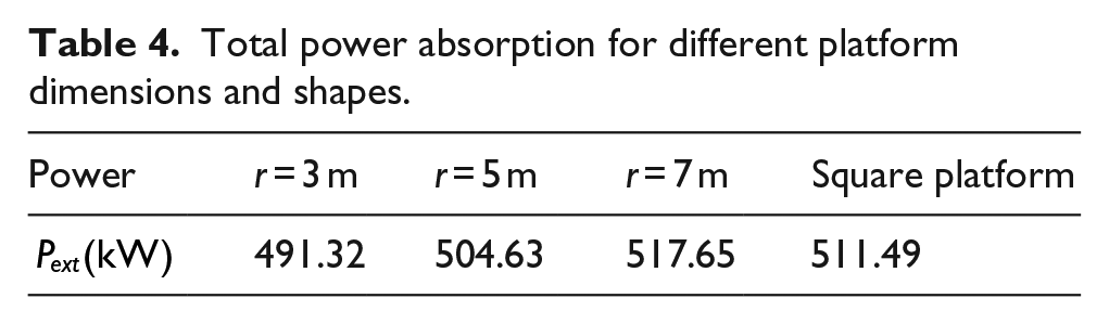
The calculations are also carried out for a bottom-mounted square platform of dimensions
Effect of change in the number of concentric circles
The effect of change in the number of concentric circles into which the 12 heaving point absorbers are arranged is presented in this section. The new array arrangement is denoted by c4 with floaters placed into three concentric circles as shown in Figure 5. The floaters in the outer circle are placed at a radius of 24 m as in the configurations before; however, there are only four floaters in each of the circle. The floaters in the second circle are placed at a radius of 17 m and at an angle of 30° from the floaters on the outer circle. Finally, the floaters on the inner circle are placed at a radius of 10 m and at an angle of 60° from the floaters on the outer circle. The results for the new concentric configuration c4 are compared with that of c2.
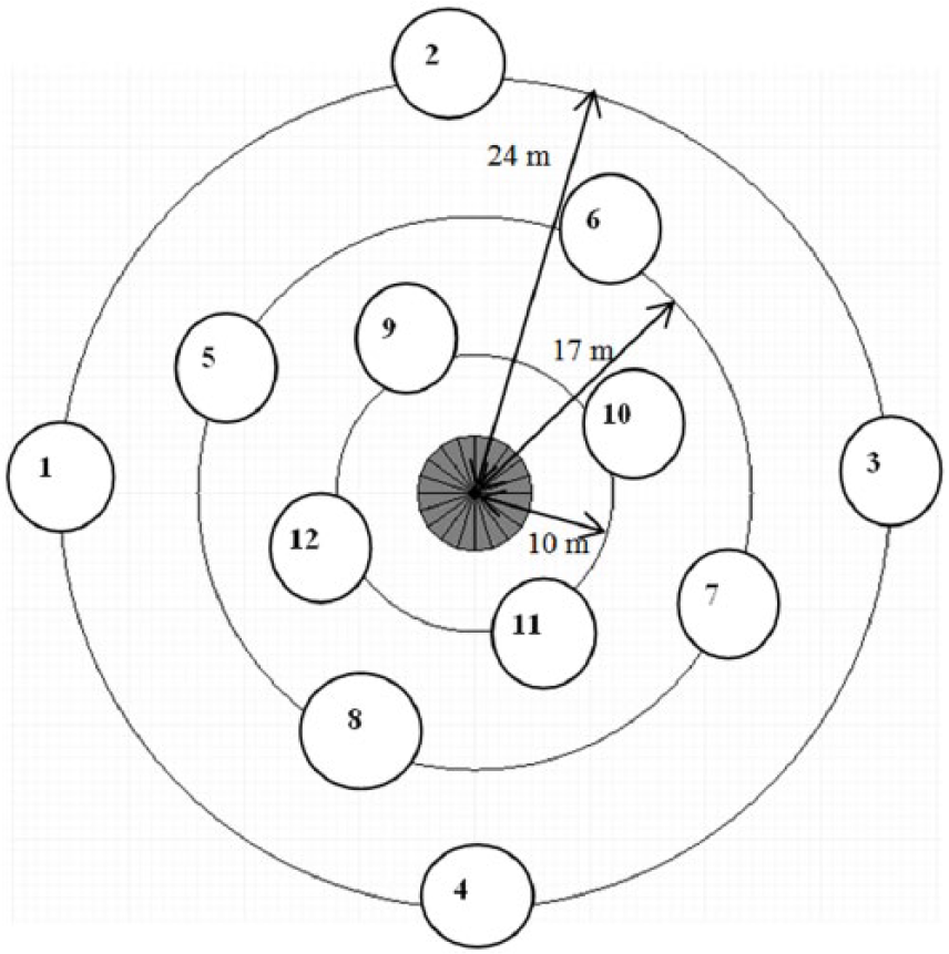
Concentric array of floaters arranged into three concentric circles.
Figure 6 shows the power extracted by each floater in both the configurations c2 and c4 for sea state SS-5. There is a variation in the performance of each floater as they are placed in different positions relative to the central platform. For configuration c4, the floaters at positions 5, 8, 9 and 12 absorb the most power with the floater numbered 12, being the closest to the platform, performing the best. Moreover, the external damping coefficients and the supplementary mass coefficients for the floaters are more uniform in the case of configuration c2 as compared to c4.
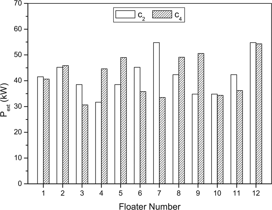
Power extracted by each floater for two different concentric arrays.
Even though there is a difference in the performance of each floater, the total power absorption is almost the same (around 504 kW) in both the arrays. Thus, changing the array arrangement from two to three concentric circles, that is, from c2 to c4 is not beneficial and will lead to higher costs. The study was also extended to four-circle concentric arrangement, and it is observed that there is a slight increase in the total extracted power. However, the increase in the power values is not big enough to make it economically viable. Moreover, a concentric arrangement with more circles would be more difficult to maintain and more complex to control.
Conclusion
The behaviour of arrays of 12 heaving point absorbers arranged in various concentric arrays is analysed in unidirectional irregular waves. The concentric arrays vary in terms of the outer and inner radii where the floaters are arranged. Six floaters are placed on the outer circle and six of them are placed on the inner circle, equidistant from each other – 60° apart. The external damping and supplementary mass coefficients have been optimized to maximize the power absorption by each floater in the array. The concentric array with an outer radius of 24 m and an inner radius of 12 m extracts the most power, and the total power absorption initially increases with increase in the array radius and then decreases. Hence, it is important to consider the radius of concentric array while designing the WEC for optimal performance.
The floaters facing the incoming waves absorb the most power, as expected, but the results are the best for the array c1, the one with the least radius. The study carried out is important to know the efficiency of each position of the floater in the array, relative to the fixed platform. The effect of changing the platform radius is analysed, and it is seen that the platform with the largest radius, r = 7 m, absorbs 5% more power as compared to the one with a radius of 3 m. Therefore, a structural and cost benefit analysis, together with the results obtained in this article, must be performed to determine the best possible dimension and shape of the bottom-mounted platform for optimal power extraction.
Furthermore, the floaters are arranged into concentric arrangements with more circles and from the results, it is observed that the increase in power absorption is not high enough to overcome the increase in the costs and the loads to build and maintain a concentric arrangement with more than two circles. This preliminary hydrodynamic study performed in this article will be useful to design an efficient WEC with concentric array of floaters.
Footnotes
Declaration of Conflicting Interests
The author(s) declared no potential conflicts of interest with respect to the research, authorship, and/or publication of this article.
Funding
The author(s) disclosed receipt of the following financial support for the research, authorship, and/or publication of this article: This study has been supported by the Portuguese Foundation for Science and Technology (FCT) through its annual funding to the Centre for Marine Technology and Ocean Engineering (CENTEC).