
Abstract
Hummingbirds and many flying biological organisms use a method known as wing kinematics modulation (WKM) for flight control and stability. This technique involves actively varying the wing flapping kinematics during flight to generate control forces and moments in response to desired trajectories, external perturbations, and natural instabilities. Recently, we designed, developed, and free-flight tested a biomimetic robotic hummingbird which uses these methods for flight control. For longitudinal control, two methods were implemented: (1) flap plane tilting which generates a coupled pitching moment and horizontal force, and (2) wing stroke mean shifting, which moves the longitudinal position of the aerodynamic center relative to the center of gravity, generating a pure pitching moment. The robot was flight tested in hover using each of these control methods. The first method resulted in higher translational velocities, larger attitude angles, and higher pitch rates, as well as off-axis roll and yaw rates. The second method resulted in significantly less movement. These results suggest that the plane tilting method is best for introducing larger changes in states, while the mean shifting method is best for more precise hovering. This is the first experimental study to quantify the effects of biological flight control strategies on the hovering flight of a two-winged, free-flying robotic hummingbird. These results could be used to inform roboticist on the best methods to use for controlling the longitudinal dynamics of flapping wing robots, as well as derive control schemes that leverage the two methods for quick and efficient execution of flight maneuvers.
Introduction
Hummingbirds are capable of many types of flight, including hovering, forward, backward, and maneuvering flight.1–5 These birds use variations in the wing flapping kinematics to control the magnitude, direction, and location of the force vector generated by each wing to control roll, pitch, and yaw motion.1–7 This technique is known as wing kinematics modulation (WKM), and has been studied extensively using high-speed videography. One of the first wing kinematic modulations observed and documented is the simultaneous and synchronous tilting of the wing flapping planes either forward, backward, or side-ward relative to the body, thus tilting the force vector in the same direction.1–5 This action generates both a rotational moment about the body center of gravity (CG), as well as a significant horizontal propulsive force which accelerates the bird in the desired direction. For controlling motion about the three flight axes, various kinematic adjustments are utilized:
Pitch rotation: Shifting the mean wing stroke positions symmetrically moves the aerodynamic center (AC) longitudinally thereby generating a pitch moment.
3
Roll rotation: Varying the relative amplitudes, and therefore the speed and lift generated by each of the wings asymmetrically generates a moment for roll control.3,6 Yaw rotation: Adjusting the flapping plane tilt, wing rotation angle, and amplitude asymmetrically provides a pure yaw control moment in hovering flight.
7
These WKM techniques are employed for both stabilization and flight control, and are sometimes executed on a stroke-by-stroke basis.3,7 Additionally, these methods of flight control have also been observed in small two-winged hovering insects such as fruit flies 8 and honeybees. 9 The presence of this method of flight control at both insect and hummingbird scales underscores its effectiveness and versatility.
While these studies have provided insights into the relationships between wing kinematic variations and resulting body movements, these relationships have not been fully explored. For example, the magnitude of the body response to different WKM methods, the effectiveness of different control techniques in achieving hovering flight or executing specific maneuvers, or the off-axis response to different WKM inputs have not been measured. Exploring these may provide quantitative insight into the methods hummingbirds utilize to perform specific flight maneuvers. Additionally, quantifying the relationships between wing kinematic variations and measured body velocities could help with the development of flight control schemes for flapping wing micro-air-vehicles (MAVs), enabling them to execute complex maneuvers more quickly and efficiently. As such, the goal of the research presented in this paper is to begin to quantify these relationships by exploring the longitudinal control and response of two-winged, flapping wing flight in hover.
To accomplish this objective, a biomimetic robotic hummingbird, the Texas A&M University (TAMU) robotic hummingbird, 10 was designed, developed, and flight tested. The TAMU robotic hummingbird is shown in Figure 1. This robot was developed to explore hummingbird flight dynamics. As such, several of the same WKM techniques observed in biological flyers are incorporated into the robot flight control mechanisms. In this manner, the TAMU hummingbird differs from other two-winged, hover-capable flapping-wing robots including the Nano Hummingbird, 12 COLIBRI, 13 and the KU-Beetle, 14 which are controlled by adjusting the tension of the wing membrane, not by WKM. Because this control method is not biomimetic, its suitability in the present study is uncertain. Some tiny two-winged flapping wing robots have been developed which use WKM techniques, including the Harvard RoboBee 15 and the flapping-wing MAV (micro air vehicle) by Tu et al. 16 These robots require a tether to a ground-based power supply, which would likely introduce errors in measuring the free-flight aircraft flight dynamics, which is the focus of this study. Later versions of the RoboBee featured an ob-board power source 17 ; however, in these prototypes, a multiplicity of wing pairs were introduced, which is a common design choice among flapping-wing MAV developers in order to increase the lift generation and flight stability of small-scale flying robots.18–20
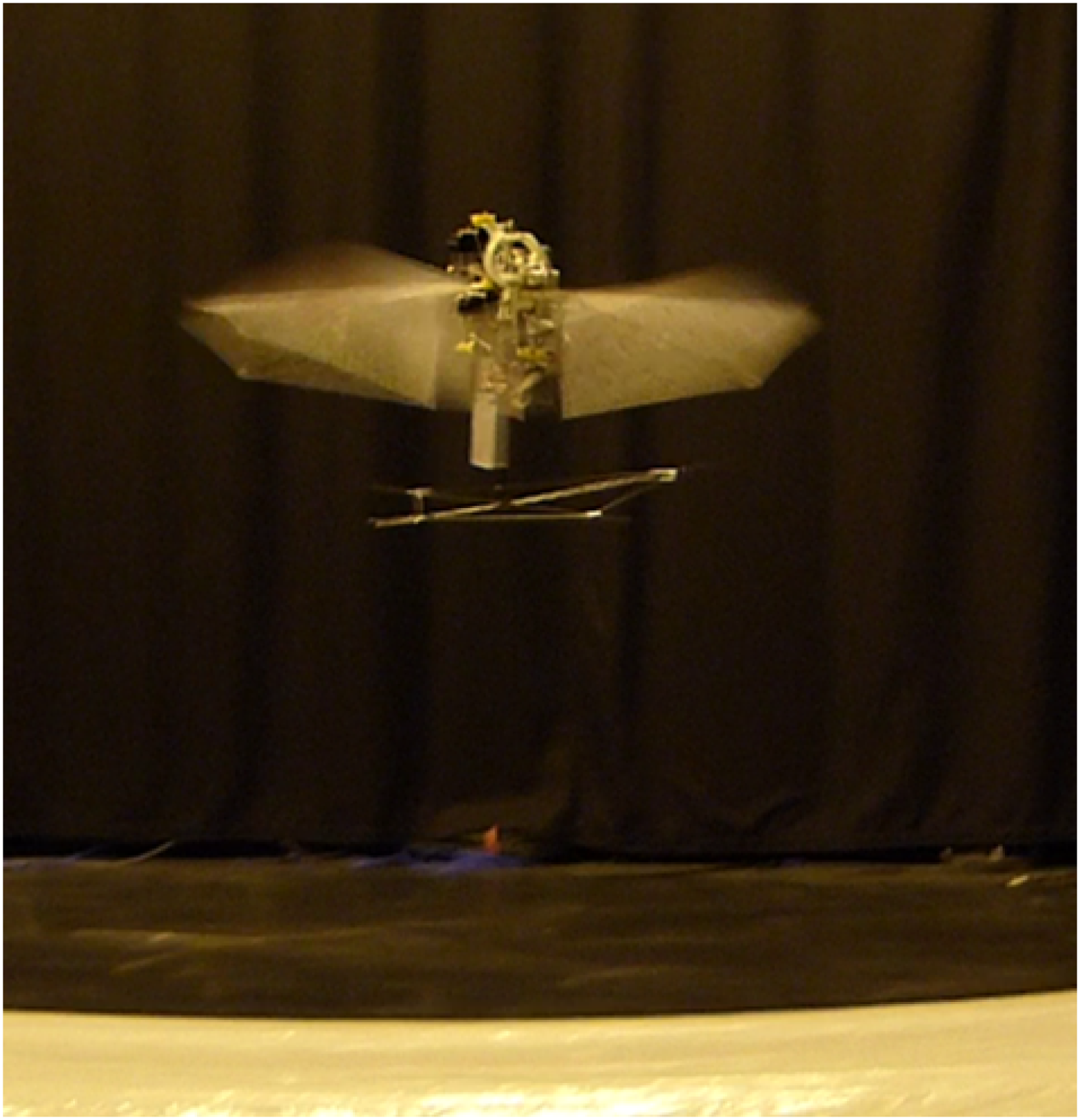
Texas A&M robotic hummingbird in hovering flight. 11
The TAMU hummingbird features two methods for controlling longitudinal motion: independent forward and backward flap plane tilting of each wing, and symmetric flap stroke mean shifting of both wings. The initial prototype featured only the plane tilting method, and was used to develop a linear flight dynamics model of two-winged hovering flight.10,21 The current prototype features both control techniques. A mechanism for shifting the mean stroke position was developed which provides precise and active control over the position of the AC relative to the CG.
Some differences in the dynamics of the hummingbird are expected when using the plane tilting method for hovering flight control versus the mean shifting method. Although both methods control the longitudinal dynamics of the robot, they accomplish this differently. The plane tilting method creates lift-generated moments and introduces horizontal force components. The action of tilting the flapping planes forward and back may introduce momentary imbalances in vertical and horizontal force components resulting in non-zero lateral and directional moments and thus motion of those axes. As such, it is expected that when using the flap plane tilting method, larger longitudinal translation as well as lateral and directional off-axis responses will be observed. Since this method cannot precisely position the AC relative to the CG, larger attitude angles and rates may be experienced due to slight differences in the AC-CG placement. On the other hand, the mean shifting method generates a pure pitching moment by shifting the average stroke position, and thus the AC, longitudinally relative to the CG. With this method, any off-axis response is likely to be smaller, and the robot will likely achieve a more precise hovering with lower amplitude attitude angles and rates.
In this paper, the effect of each control technique on the longitudinal flight dynamics states during hovering flight of the TAMU robotic hummingbird is investigated and quantified. A brief overview of the vehicle design is provided, along with a detailed description of the mechanical implementation of the longitudinal control methods. Flight experiments were conducted with the vehicle wherein the two different control methods were utilized to stabilize the vehicle in hovering flight, and the robot position, attitude, and translational and rotational velocities were measured. Twelve flight tests were conducted wherein the flap plane tilting method was used, and twelve were conducted wherein the stroke mean shifting method was used. The inertial position, attitude angles, and body rates and velocities were measured and extracted for the portion of the flights wherein the vehicle was in hovering flight. The resulting experimental flight test data and analysis is presented below.
Vehicle design
An overview of the design of the first prototype of the TAMU robotic hummingbird, including the wings and 5-bar flapping mechanism, has been presented previously. 10 The robot design was modified and a new prototype developed. The differences between the two are discussed here.
A mechanism was designed and incorporated into the robot which would shift the average flap stroke position using a rotary actuator. The design of the robot was improved to house the mechanism concisely without increasing the weight significantly. The vehicle body, which anchors the mechanical subsystems including the wing flapping drive motor, flapping mechanism, and wing kinematics modulation mechanisms, was rapid prototyped using a low-density (0.303 lb/in3, 0.84 g/m3) Nylon-based material with a high tensile strength and had a mass of 5.65 grams. Additionally, the shoulder bolts used in the flapping mechanism were manufactured in-house using 7075 T-6 aluminum. A carbon fiber structure supports the electronics and battery pack. Figure 2 shows the hummingbird with key components labeled, and a weight breakdown of the vehicle subsystems is provided in Table 1. The design of some of the key subsystem components is described in the subsequent sections.

Robotic hummingbird with key components labeled. 11
Component weight breakdown of robotic hummingbird subsystems. 11

Flapping mechanism
A 5-bar flapping mechanism was developed to generate large amplitude flapping motions by combining a traditional 4-bar crank-rocker mechanism with an added 5th bar which amplifies the output of the 4-bar mechanism. 10 The 5th bar, which is the wing itself, flaps through a stroke amplitude of approximately ±60°. The mechanism is shown schematically in Figure 3. In this schematic, the rotation of the flapping drive motor is converted to reciprocating motion through links l2, l3, l4, and l5. The first link, l1, is the distance between the rotation axis of the mechanism input shaft, and the flapping axis of the output linkage, l4. These elements of the mechanism are the same as those in the first robot prototype.

Schematic of modified 5-bar flapping mechanism with linkages and key components labeled. 11
For the current prototype, the flapping mechanism was modified by introducing an additional degree of freedom at point C, the hinge point for the output flapping link, l4 (see Figure 3). That point, the l4 flapping axis, can be actively moved through a semi-circular trajectory via an actuator. As the hinge point C is shifted upward in the trajectory through the action of the actuator, it pulls the wing with it, thus shifting the average stoke position accordingly. The opposite occurs when the hinge point C is moved downward in the semi-circular trajectory. A photograph of the mechanism on the vehicle with linkages labeled is shown in Figure 4.
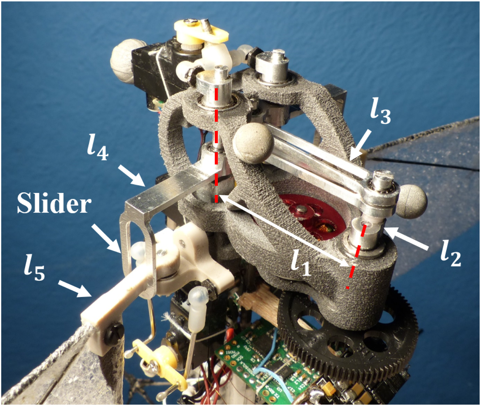
Close-up photograph of flapping mechanism with linkages labeled. 11
Wing kinematics modulation methods
The wing kinematics modulation techniques implemented on the TAMU robotic hummingbird are the same as those observed in two-winged, hover-capable, biological flyers. Here, the two methods used to control the longitudinal dynamics are discussed. These are: (1) symmetric tilting of the right and left wing flapping planes, and (2) symmetric shifting of the right and left wing strokes.
Symmetric flap stroke plane tilting
The flap plane tilting method was implemented on the first robotic hummingbird prototype, and was discussed in a previous work. 10 Here, a brief overview is provided. For this method, the right and left flapping planes are tilted symmetrically and synchronously either forward or backward. This action generates a coupled lift-induced pitching moment and translational force. This is demonstrated in Figure 5, which shows the outline of the wings level position of the right and left wing planes, along with the flapping planes tilted forward. This WKM method orients the lift vectors vertically for hovering flight and controls and stabilizes longitudinal translation.

Symmetric flap stroke mean shifting
The flap stroke mean shifting was first implemented on the current robot prototype. In this method, the mean stroke positions of the right and left flapping planes are shifted symmetrically and synchronously forward or backward. This action generates a pure pitching moment by shifting the mean stroke position and therefore the longitudinal position of the AC relative to the CG. As the flap stroke and therefore the AC is shifted relative to the CG, an offset is introduced in the longitudinal direction between the lift vectors and the CG and thus a pitching moment. This action is illustrated schematically in Figure 6, which shows the outline of the wing sweep in the neutral position, and the new sweep area after the mean has been shifted forward. The left and right wing lift vectors are denoted LL and LR respectively, and the longitudinal distance between the AC an CG is denoted as dAC.

Schematic of stroke mean shifting for pitch control. The wing AC follows the wing mean stroke position, and is shifted forward a distance of dAC from the CG. The offset of the lift from the CG generates a pitching moment. 11
The average stroke position of the wings is shifted by moving the location of the l4 rotation axis, the output linkage of the 4-bar mechanism. As discussed above and shown in Figure 3, the rotation axis at point C can be moved along a semi-circular trajectory in the flapping plane. Because the arc length is very short, the motion is mostly longitudinally, and changes the length of l1. This is an effective method for changing the mean output angle of the wing due to the mechanical design of the flapping mechanism. Any shift in the output flapping angle of l4 as it flaps about its rotation axis (point C in Figure 3) is amplified by the 5-bar mechanism design. This means that small shifts in the location of the l4 flapping axis will result in shifts in the wing flapping angle which are proportional to the amplification factor. For clarity, the wing flaps about point E in the figure, and is driven by l4 via the sliding contact between l4 and the wing, l5, at point D. The l4 flapping axis can be shifted by approximately ± 1.0°, and the amplification factor is about 3.2. As such, the flapping angle of the wing to be shifted by ±3.2°. A simple equation for the amplification factor can be expressed by dividing (1) the length of l4 between its flapping axis at point C and the sliding contact with the wing at point D by (2) the length of the wing between its flapping axis at point E and the sliding contact point at D:
The shifting of the mean flap stroke angle ultimately results in a change in the longitudinal position of the aerodynamic center. Given the wing length of 5.5″ (14 cm),
10
and an aerodynamic center of the wing located at the 70% percent radial location,
22
the shift in the AC location in the longitudinal direction can be calculated as follows:
This range of possible longitudinal movement of the AC position is enormous relative to the size of the vehicle, and encompasses the CG and approximately one-third the length of the body of the robot in the longitudinal direction. As such, this wing modulation technique was used to precisely position the AC longitudinally relative to the CG by shifting the mean position of flapping until pitching tendencies were eliminated. This method allowed trimming the vehicle in hovering flight as well as controlling and stabilizing pitch.
Wing kinematics modulation actuation
With the methods for controlling the longitudinal flight of the robotic hummingbird determined, mechanisms were developed for implementing the wing kinematics modulations during flight. The mechanisms were designed to control and maintain the wing positions and kinematics even under large vibratory loads. The WKM mechanisms were controlled with lightweight, high torque Power HD® DSP-33 digital micro-servos.
Flap stroke plane tilting mechanism
For flapping plane tilting, the wing mounts are rotated about an axis concentric with the lateral axis of the vehicle. The wing mounts hold the wings in a plane while allowing them to flap freely about their respective flapping axes. The servo arm rotates, and this motion is transmitted via a set of pitch links to the wing mount resulting in a tilting of the flapping plane. This is similar to how blade pitch control inputs are communicated to helicopter blades through pitch links from the swashplate. The wing flaps freely on the wing mount while following the plane angle; therefore, as the wing mount tilts, the wing flapping plane and angle of the lift vector follow. This action is shown in a sequence of photographs in Figure 7. On the current prototype, the plane can be rotated by ±30°, which is the range of the servo.
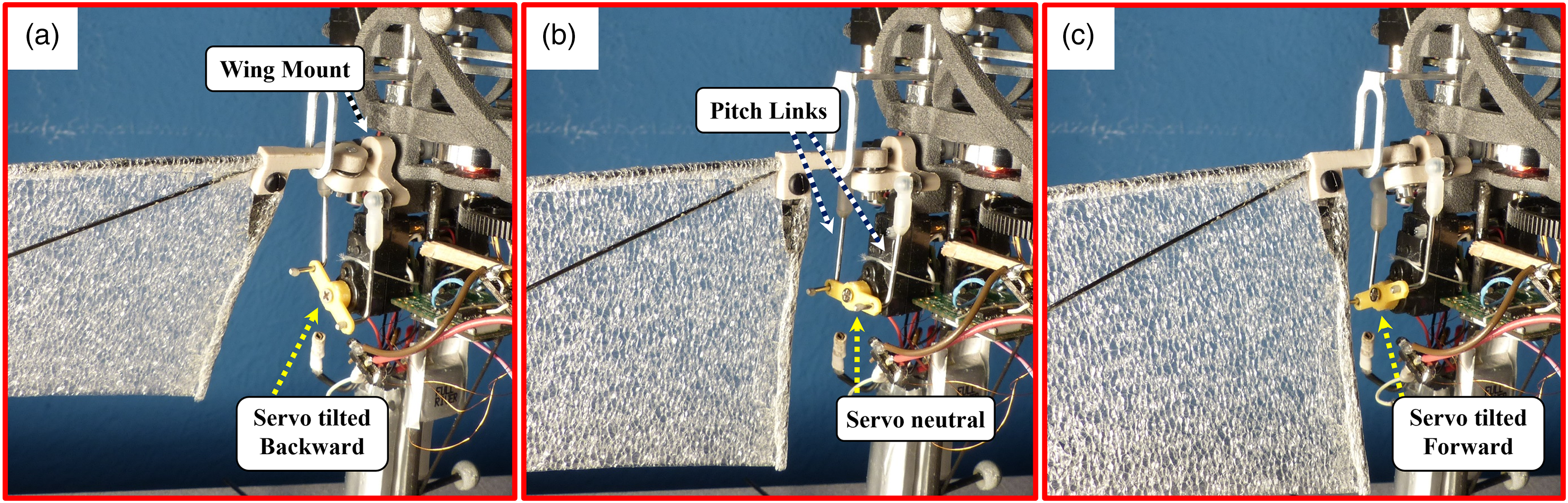
Mechanical implementation of flapping plane tilting. (a) Left wing plane is tilted backward which tilts the lift vector in the same direction resulting in a horizontal force. (b) Flapping plane in neutral position. (c) Left wing plane tilted forward which tilts the lift vector forward. 11
Flap stroke mean shifting mechanism
For mean flap stroke position control, the l4 flapping axis is moved longitudinally, thus changing the length of l1 (see Figure 3). By shifting the l4 flapping axis, the mean angle about which l4 flaps also shifts. Because l4 drives the wing, the mean flap position of the wing moves accordingly. In the mechanical implementation on the robotic hummingbird, a servo arm transfers rotational motion to a rotating pivot to which the l4 flapping is mounted at an offset from the pivot axis of rotation. As the servo rotates forward and backward, the pivots also rotate, shifting the l4 rotation axis and the mean flapping position accordingly. A sequence of photographs is provided in Figure 8 which shows the mechanism including the servo, pivot axes, and l4 and wing flap angles in forward, neutral, and backward positions.

Mechanical implementation of flapping stroke mean shifting. (a) Mean l4 and wing flap angles shifted forward, shifting the mean position of the aerodynamic center forward longitudinally. (b) Flapping angles in neutral position. (c) Mean l4 and wing flapping angles shifted backward, moving the aerodynamic center accordingly.
The l4 flapping axis is mounted to a rotating pivot, but the l4 flapping axis is not concentric with the rotation axis of the pivot. As such, when the pivot rotates, the l4 flapping axis translates and rotates about the pivoting axis, following the semi-circular arc shown in Figure 3. This is similar to an engine crankshaft in which the crank throw axis (l4 axis) is offset from the shaft axis (pivot axis) of rotation. The pivot is rotated by a servo output shaft via a mechanical link. The amount of rotation of the pivot is small, resulting in mostly longitudinal movement of the l4 flapping axis. This movement of the l4 axis shifts the l4 output angle and finally the wing output angle. A photograph of the mechanism with the wing stroke shifted forward is shown in Figure 8(a). Here, the pivots are rotated forward, shifting the l4 flapping axis and thus the wing output angle accordingly. Figure 8(b) shows the mechanism in the neutral position, and Figure 8(c) shows the pivots rotated backward and the flap angles shifted accordingly. Some of the movements are exaggerated in the figure to illustrate the mean shifting operation. Currently, the pivots can rotate through about ±30°, and the offset distance between the l4 axis and the pivot axis is 0.025 inches (0.635 mm) laterally. Although the movement of the l4 axis is quite small, once the output of the l4 link is amplified by the final link, l5, the mean flapping angle can be changed by approximately ±3.2°.
Experimental methodology
With the wing kinematics modulation mechanisms implemented on the vehicle, including the two for longitudinal control, the robotic hummingbird more closely mimics two-winged hover-capable biological flyers than the previous prototype. With this biomimetic flight control scheme, it was of interest to experimentally flight test the vehicle while using first the flap plane tilting to control the longitudinal motion, and then the mean stroke shifting and quantify the difference in flight behavior. A series of systematic experimental flight tests were conducted to investigate the flight performance of the robotic hummingbird using the two different longitudinal control techniques.
Due to the unstable nature of the aircraft as well as its relatively fast dynamics, a stability augmentation system (SAS) was necessary to control the vehicle. A Proportional-Derivative (PD) controller was programmed onboard the custom autopilot, ELKA, which was designed specifically for micro-air-vehicle applications. 23 It is a lightweight, 1.3 gram SAS (stability augmentation system) controller with tri-axial gyroscopes and accelerometers as well as bi-directional communication with a ground station. The vehicle was first trimmed for hovering flight, and then the attitude and rate feedback gains on ELKA were tuned for stable hovering flight in a procedure similar to that documented previously. 10 Once completed, the performance of the vehicle could be quantified by experimentally flight testing the aircraft and measuring the vehicle states.
Flight data collection
To capture the vehicle states during flight testing, the vehicle was flown in a laboratory space equipped with a set of six VICON motion capture cameras. These cameras created a capture volume of approximately 15 ft × 15 ft × 7 ft (4.6 m × 4.6 m × 2.1 m). To track the vehicle pose, each VICON camera beamed a low frequency light and measured reflected infrared light from four lightweight, reflective beacons fastened to the vehicle. The VICON software was programmed to recognize the robotic hummingbird based on the pattern of reflected light that matched the maker placement on the vehicle. The VICON system had an update rate of 100 Hz, but the recording rate was limited by the base station, which was 50 Hz. To provide a safe landing zone for the vehicle, a flexible plastic sheet 90 µm thick and having a width and length slightly greater than the capture area was suspended a few inches above the ground. In the event of a crash landing, this suspended ground provided a soft landing area for the vehicle. The laboratory setup is shown in Figure 9.
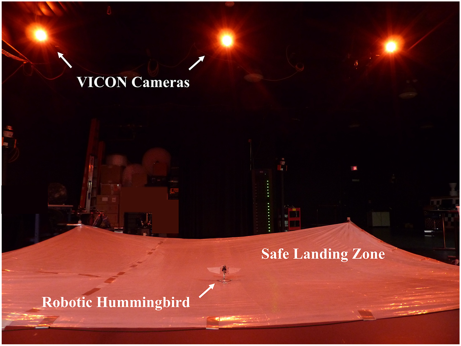
Data collection experimental setup in the lab showing the VICON cameras, safe landing zone, and robotic hummingbird within the capture volume. 11
During the flight tests, the VICON cameras tracked the inertial position of the center of mass, [Xi, Yi, Zi], and the Euler parameters (quaternions), [β0, β1, β2, β3]. From these data, the roll, pitch, and yaw Euler angles, [ϕ, θ, ψ], and body-axis angular rates, [p, q, r], as well as body-axis velocities, [u, v, w], were derived. The data was transmitted wirelessly to a LabVIEW® base station and saved at 50 Hz.
Flight testing procedures
The purpose of the present study was to quantify the performance of the robotic hummingbird in hovering flight using the two different methods of longitudinal control. As such, flight experiments were conducted in which hovering flight was attempted and maintained to the best extent possible. Generally, a flight profile consisted of (1) take-off, (2) vertically ascend to an altitude of a few feet, (3) hover while stabilized during which control inputs were provided to reduce drift, (4) descend, and (5) land. The hover lasted until the battery was depleted, the vehicle drifted outside the capture volume, or the trim changed due to mechanical vibrations which made control difficult. Flight test data was collected for the entire duration of the each flight. For these experiments, two sets of flight experiments were conducted. For the first, flap plane tilting was utilized for pitch control, and for the second, the mean stroke shifting method was utilized. A total of twelve flight test data points were collected for each of the longitudinal control methods for a total of 24 experimental data points.
Before conducting these flight experiments, a trim procedure was established and the feedback gains were tuned to ensure that the effect of the trim and feedback gains were constant across all flight tests. To trim the aircraft, the four wing kinematic actuators were set to the same position before each flight test. The two flapping plane actuators were positioned such that the wing flapping planes were horizontal and perpendicular to the vertical axis of the vehicle. This position removed any yaw bias or horizontal force generation. The roll and mean shifting actuators were centered to eliminate roll or pitch bias. The actuators were also checked for operational integrity to ensure they were capable of adjusting the wing kinematics as needed.
The feedback loops were tuned to ensure consistent performance of the robot independent of which longitudinal control technique was used. The pitch controller PD gains were tuned when implementing each control technique to ensure that the aircraft performed well with each method. The roll and yaw PD gains were tuned in independent efforts and the values remained constant across all the flight experiments presented here. The feedback gains in the PD loops were tuned such that the flight performance was the best possible: higher feedback gains resulted in undesired oscillations, while lower resulted in the vehicle drifting and poor tracking of the inputs. Significant effort was put into tuning the PID feedback gains with each of the control methods such that the robotic hummingbird achieved the best possible flight with minimum oscillation for both control schemes. For this reason, the tuning of the PID feedback loops was not considered a significant factor in the resulting hovering performance between the two control methods.
Results and discussion
To quantify the resulting difference in flight performance between the two longitudinal control methods, three categories of experimental flight test data were examined: (1) translational motion of the center of mass, which included spherical error probable (SEP) calculations and drift speed; (2) the longitudinal kinematics, which included the body-axis longitudinal velocity, pitch attitude angle, and pitch rate, and (3) lateral and directional kinematics, which included roll attitude angle and roll and yaw rates. Previous studies with real hummingbirds have shown that changes in wing kinematics were correlated primarily with the body angular velocities rather than accelerations, hence accelerations are not considered here. 3
The position and velocity quantities were extracted from all 24 data sets, twelve from each of the two control methods. Since the focus of this study was on the effectiveness of the control methods in achieving and maintaining hovering flight, the data was extracted during the portion of the flight during which hovering flight was performed. These selected quantities are presented and discussed below, along with the mean and standard deviation calculated across each of the twelve data sets for the two control methods.
It is noted here that the mechanical state of the robotic hummingbird may have a non-zero effect on the results of the flight testing. For example, the magnitude of the measured oscillations or the movement of the aircraft during hover may vary slightly depending on the mechanical condition of the robot. However, this effect is expected to be random and independent of which control scheme is being tested and therefore not impact the trends in the data or the conclusions from this study. One example of the mechanical states that may affect the results is the condition of rotational points such as axles, pivots, and bearings that wear out with time causing slight deviations in the wing kinematics from the desired kinematics. Another example is the flight time on the wings. As the wings are used, the AC location within the stroke shifts slightly causing slight imbalances in the moments. Finally, the mechanical condition of the servos such as the tightness or looseness of the output shaft may affect how precisely the wing kinematics can be controlled. These mechanical variations are small, and may explain variations in the measured flight performance even when the trim and feedback gains were set the same for each test. As such, part of the research question being addressed here is concerned with which control scheme is more robust in handling small differences in the system to achieve and maintain hovering flight.
Before examining the hovering flight performance and longitudinal state data, the data from the onboard flight controller, ELKA, and the external motion capture system, VICON, were compared. The purpose of this effort was to quantify the similarity between the two data sets to verify agreement between the two independent measurements. The measurements from ELKA and VICON for the pitch attitude angle, θ, and roll attitude angle, ϕ, were compared for a flight test during which the aircraft maintained hovering flight. The maximum cross-correlation between the two measurements were calculated for the two angles. The flight test data and normalized cross-correlation calculations are shown in Figure 10, which demonstrate excellent agreement between the two measurements. The normalized cross-correlation between ELKA and VICON for the pitch angle was calculated to be 0.989. For the roll angle, the value was 0.973.

Comparison between measured pitch and roll Euler angles from the onboard flight controller, ELKA, and the external motion capture system, VICON.
Translational motion
To quantify the amount that the robotic hummingbird moved relative to a fixed point in space during hovering flight, and thus the effectiveness of each control method in maintaining hover, the translational motion of the vehicle was considered. An imaginary sphere encompassing at least half of the flight path during hover was used to quantify how well the robot held its position: the smaller the sphere, the more precisely the vehicle held its position. The size of the sphere was determined by calculating the spherical error probable for each flight for the duration of the attempted hover. SEP calculations are often used in GPS applications to determine how precisely position can be determined, and has also been used to quantify the deviation of an MAV from hover position when subjected to wind gusts. 24 The SEP is a measure of the radius of a sphere centered at the average position of the robot during hover such that 50% of the flight path is contained within the sphere by considering the standard deviations of the inertial positions, [Xi, Yi, Zi], during the flight test.
Two diagrams illustrating the SEP concept based on the flight trajectory of the robotic hummingbird during approximately 3 seconds of attempted hover are provided in Figure 11 for the plane tilting method and in Figure 12 for the mean shifting method. Included in each figure are several snapshots of the robot while in flight overlaid on a single image. The flight path of the robotic hummingbird is shown as a dashed line, and a SEP sphere is drawn over the flight path which encloses approximately half the flight trajectory. A scale is provided for reference. These results are representative of those observed during flight testing.

Illustration of spherical error probable and flight path of the robot hummingbird for an approximately 3-s hovering flight attempt in which the stroke plane tilting method was used for longitudinal control.

Illustration of spherical error probable and flight path of the robot hummingbird for an approiximately 3-s hovering flight attempt in which the stroke mean shifting method was used for longitudinal control.
These results demonstrate qualitatively that the SEP sphere was larger for the flight experiments in which the plane tilting method was used, and smaller for the experiments in which the mean shifting method was used. This result indicates that the robot experienced less drift and better hovering characteristics when the mean shifting method was employed. To quantify the results, the spherical error probable was calculated for all of the 24 flight experiments. These results are provided in Figure 13. Here the difference in aircraft drift while hovering when using the two different control methods can be further observed. With the plane tilting method, the average SEP is 2.2 ft (0.67 m) with a standard deviation (STD) of 0.62 ft (0.19 m). This result means that a sphere with a radius of 2.2 ft would contain the flight path of the vehicle during hovering. Conversely, when implementing the mean shifting method, the average SEP was reduced by nearly 71% down to 0.65 ft (0.21 m) with a standard deviation of 0.35 ft (0.11 m). This reduction in SEP size and variation across flight tests demonstrates the improvement in the ability of the latter method to more precisely maintain the position of the robotic hummingbird in space during hover. It appears that using the flap plane tilting for controlling the longitudinal motion results in significantly more movement and less consistent hover, likely due to the horizontal forces introduced by the tilting action.

Spherical error probable for each flight experiment using the two methods of longitudinal control.
The translational motion of the CG of the robot in the hovering plane was also quantified by calculating the average speed of the vehicle during attempted hover. This speed, denoted Planar Drift Speed, was calculated from the time derivatives of the measured inertial position, [Xi, Yi]. For an ideal point hover, Planar Drift Speed is zero, while in the current real-world application, some drift is expected. For these experiments, the drift speed was expected to decrease when implementing the control method that is more capable of maintaining a precise hover. The drift speeds of the 24 flight experiments were calculated, as well as the average and standard deviation for the two control types. These results are plotted in Figure 14, which demonstrates a difference in the hovering flight performance between the two control methods. The average drift speed for the experiments in which the plane tilting method was used was 2.17 ft/s (0.66 m/s), and decreased by 64% to 0.78 ft/s (0.24 m/s) for the flights in which the mean shifting method was utilized.

Planar drift speed for each flight experiment using the two methods of longitudinal control.
This result demonstrates a significant reduction in the overall motion of the robotic hummingbird with the latter method, and suggests that greater control authority over pitching motion of the robot is offered by the mean shifting method. The standard deviation of the twelve measurements for the flight tests in which the plane tilting was utilized was 0.5 ft/s (0.15 m/s), while that of the data points in which the mean shifting was used was reduced to 0.31 ft/s (0.1 m/s), demonstrating that the robot behaved more consistently in hovering flight with the latter method. Together, the drift speed and SEP calculations demonstrate that the use of the flap stroke mean shifting method results in overall less vehicle motion and more precise hovering, while the flap plane tilting method introduces significantly more movement of the CG. The choice of which method to use for controlling the robotic hummingbird in a given scenario depends on the desired flight behavior. Precise position holding likely requires a method such as stroke mean shifting to accurately place the AC relative to the CG, while the need to continuously stay on the move throughout a mission, for example, may be more effectively accomplished using flap plane tilting for longitudinal control.
For the robotic hummingbird, the electrical power drawn was determined by the flapping motor, the wing kinematic actuators, and the flight controller. The power drawn was dominated by the flapping motor, which far surpassed that required by the wing kinematic actuators. Even under the highest loads, the actuators did not draw significant current, resulting in a relatively constant power consumption which was independent of which method or set of actuators were used for longitudinal control. As such, while differences were observed in the translational motion of the robotic hummingbird between the two different methods as shown here, no discernible differences were observed in the electrical power consumption. Furthermore, the total flight endurance was independent of which control method was used. However, because the vehicle tended to drift more when the plane tilting method was used, flights wherein the plane tilting method was implemented often had to be terminated earlier in comparison to flight tests in which the mean shifting method was used. This action was needed to prevent the robot from departing the capture volume as well as the safe landing zone.
Longitudinal motion
To quantify the effect of these two control methods on only the longitudinal motion of the robot, the longitudinal states measured during the flight experiments were examined. These states included: body-axis longitudinal velocity, u, pitch attitude angle, θ, and pitch rate, q. Since the flight control techniques investigated in this study affect primarily the forces along the longitudinal axes and moments about the lateral axis, it is expected that the longitudinal state quantities will vary between the two control methods. Examining the variation in these states between the two methods can provide further insight into their influence on the motion of the robot beyond simply the ability to maintain a position in space.
Body-axis longitudinal velocity
Because of the difference in drift speed observed in the flights utilizing the two control methods, and because the two methods primarily control motion along the longitudinal axis, it was expected that the behavior of the longitudinal velocity, u, would vary between the two control schemes also. For this reason, this quantity was given a more detailed investigation. Here, the average velocity of the robotic hummingbird along the body-fixed longitudinal axis during each hovering flight attempt was extracted from the flight test data. The average and standard deviation of the longitudinal velocity was calculated for the twelve data sets in which the mean shifting technique was used, and for the twelve in which the plane tilting method was used. These results are shown in Figure 15. For these results, the average longitudinal velocity was calculated from the absolute value of the measurement so as to capture the vehicle's motion independent of the direction of travel.

Average measured longitudinal velocity, u, for each flight experiment using the two methods of longitudinal control.
For the flight tests in which the plane tilting method was used, the average longitudinal velocity was 1.31 ft/s (0.4 m/s) with a standard deviation of 0.39 ft/s (0.12 m/s) across the twelve tests. The results for the mean shifting method show an average velocity of 0.44 ft/s (0.13 m/s) with a standard deviation of 0.19 ft/s (0.06 m/s), a difference of 66%. This reduction in longitudinal velocity when implementing the mean shifting technique is similar to the reduction seen in the planar drift speed (Figure 14), which is expected since the longitudinal velocity is one component of the planar drift speed. Comparing the relative magnitudes of the planar drift speed and the longitudinal velocity shows that the longitudinal velocity comprises around 60% of the drift speed. As mentioned previously in the discussion of the SEP calculations, the introduction of a horizontal force component when the flapping planes tilt as the controller adjusts the plane angles to maintain stable flight most likely results in the additional movement along the longitudinal axis.
Pitch attitude angle
The pitch attitude angle, θ, was also examined to characterize the ability of the control methods to maintain the robotic hummingbird in level attitude during hover. The pitch angle was measured relative to the horizontal plane in the inertial frame. To maintain hovering flight, the desired angle of the flapping planes of the robotic hummingbird, and therefore the pitch attitude angle, was zero relative to this plane. Here, the average pitch angle during hovering was extracted for each flight test. For the two control methods, the average and standard deviation of the twelve data points were calculated from the results.
The pitch angle results for all 24 of the flight experiments are shown in Figure 16. The average pitch angle when utilizing the stroke plane tilting for pitch control was 10.3° and this angle varied from 5° to 14° with a standard deviation of 2.5°. Conversely, the average pitch angle was reduced to 1.3° with a variation between 0° and 2° with a standard deviation of 0.8° when utilizing the mean shifting method. These results show that the mean shifting method was consistently more effective at maintaining level attitude due to the ability to adjust the longitudinal position of the AC above the CG. On the other hand, the plane tilting method resulted in larger pitch attitude angles. These results demonstrate that, even when the robot was rigorously trimmed before flight by setting the flapping planes level and perpendicular to the body of the robot, slight offsets in the relative AC and CG positions during flapping created small but non-zero moments about the CG. These moments resulted in non-zero hovering pitch angles.

Average measured pitch attitude angle, θ, for each flight experiment using the two methods of longitudinal control.
Although the desired pitch angle was zero, these results show that the robot experienced some amount of pitch angle variation regardless of the control scheme. Together with the translational motion measurements presented above, these results show that the vehicle did not maintain a perfectly motionless point hover, but did experience some oscillations and drift while attempting hovering flight. Some reasons for this observed angular and positional motion may be: (1) limitations in the precision at which the actuators were able to move or hold the position of the wing kinematics during flight; (2) limitations in the speed at which the actuators were able to adjust the wing kinematics to stabilize the vehicle; (3) initial flight conditions during liftoff, which may have perturbed the vehicle in an arbitrary direction and induced oscillations; (4) variations in the angle of the flight controller board during power up and initialization, which may have led to small and random variations in the measured attitude angles relative to level position. In accordance with the discussion above regarding the mechanical state of the robotic hummingbird, these effects were considered random and independent of the choice of flight control method.
Pitch angular rate
Finally, the pitch angular rate, q, was also examined from the flight testing data. The pitch rate was used to quantify the ability of the control methods to either reduce or increase the rotational motion of the robot depending on the desired pitch rate. For this study, hovering flight with zero pitch rate was desired; therefore, the control method which resulted in lower pitch rates would be more appropriate for hovering flight. The maximum measured pitch rate while attempting to maintain stable, hovering flight best described the nature of the longitudinal dynamics, and was therefore extracted from the experimental data. These results are shown in Figure 17, along with the average and standard deviation calculations for the data points.

Maximum measured pitch rate, q, for each flight experiment using the two methods of longitudinal control.
From these results, it can be seen that the average maximum pitch rate when utilizing the plane tilting method was 243.4°/s, with a standard deviation of 52.8°/s, or 22%. Conversely, the use of the mean shifting method resulted in a average maximum pitch rate of 115.6°/s, with a standard deviation of 41.5°/s, or 35%. Thus, the second control method was more effective in reducing the aircraft rates, although the relative variation was larger. Because the peak rates were higher with the plane tilting method, this method may be capable of generating larger pitching moments and thus angular motion than the mean shifting method. Future studies could focus on quantifying the maximum rotational accelerations possible with each control method, and explore the performance of each when large non-zero pitch rates are desired.
In addition to hovering flight, other trimmed flight conditions may require zero pitch rate, such as constant forward speed with the robot attitude set to a constant pitch angle. In these cases, it may be appropriate to use the plane tilting method to initiate a rapid rotation, then adjust the mean stoke position to minimize the pitch rate. For flight away from hovering, hummingbirds likely use combinations of both control methods, and in doing so execute maneuvers quickly and efficiently. Future studies could focus on exploring the use of combinations of the control inputs to quantify the effect of each on non-hovering and transient flight conditions.
Lateral and directional kinematics
The control methods described here primarily affect the longitudinal motion of the robotic hummingbird. However, it was of interest to also explore the lateral and directional dynamics to quantify any variation in the off-axis response to the two control schemes. As described above, the roll, pitch, and yaw axes were each controlled by an independent PD feedback loop. This method precluded any controller-induced coupling in the observed vehicle dynamics. For this analysis, the average roll angle as well as maximum roll and yaw rates were examined to quantify the difference in behavior in these axes with the different longitudinal control methods.
Roll attitude angle
The average roll attitude angle, ϕ, was extracted for each of the 24 flight tests for the time during which the robot was in hovering flight. These results are shown in Figure 18. For the experiments in which the plane tilting was used for longitudinal control, the average roll angle was ±4.3° with a standard deviation of 1.9°. For the flight experiments in which the mean shifting was utilized, the average angle was 2.6° with a standard deviation of 2.2°. Both of these average angles are small, and demonstrate that the current method of controlling roll angle is both effective and relatively independent of which longitudinal control scheme is used. The average values of both of the data sets are within one standard deviation of the other data sets, further demonstrating that roll attitude is independent of pitch control methods.

Average measured roll attitude angle, Φ, for each flight experiment using the two methods of longitudinal control.
Roll angular rate
The maximum roll angular rate, p, was also extracted from the experimental data during the portion of time during which the aircraft was in hovering flight. The results for the 24 flight tests are shown in Figure 19. For the flight tests in which the plane tilting was used, the average peak roll rate was 200°/s with a standard deviation of 55.8°/s, or 28%. For the experiments in which the mean shifting was used, the average peak roll rate was 74.6°/s with a standard deviation of 32°/s, or 43%. These results indicate that the longitudinal control methods have a non-zero effect on the lateral dynamics, especially since the trim and feedback gains for roll were constant across all flight tests and independent of the chosen pitch control method.

Maximum measured roll rate, p, for each flight experiment using the two methods of longitudinal control.
The reason for the difference in observed maximum roll rate between the two longitudinal control methods may be explained by the manner in which the plane tilting method not only changes the horizontal component of the force generated by the wings, but also the vertical component (see Figure 5 above). This variation in vertical component of forces may not be symmetric between the two wings, introducing an imbalance of forces and a momentary moment about the lateral axis. This effect works as follows.
For a flight in which the flapping planes are perfectly level for trimmed hovering flight, and the flapping planes tilt together in perfect unison to correct for pitch instabilities, no response would be expected in roll as the flapping planes tilt to correct for pitch instabilities. However, there are situations in the real world robot in which this is not the case. For example, suppose that to properly trim yaw for hovering flight, it was required that one flapping plane be tilted slightly forward and the other slightly backward. In this scenario, the vertical components of the wing forces ar equal. balancing roll. However, as the flapping planes tilt in the same direction to correct for pitch instabilities, the vertical component of one wing would increase, while the other would decrease, leading to a roll imbalance and an increase in roll rate. However, the roll PD feedback would correct for this change in angle and rate, keeping the average roll Euler angle small although a peak may be observed in the roll rate.
Another example would be when the flapping plane actuator movements are not perfectly identical between the two wings, which is expected in the real-world robot. In this case, the two flapping planes may not tilt through precisely the same number of degrees of rotation, or at precisely the same rate. This asymmetry in actuator movement may lead to momentary imbalances between the left and right vertical force components, generating a non-zero rolling moment which the roll PD controller would correct for. These results suggest that the plane tilting method should be utilized during maneuvers requiring higher rates and less precision, while the mean shifting technique should be used for flights requiring smaller off-axis movements and greater precision.
Yaw angular rate
Finally, the yaw rate, r, was examined to determine the presence of any directional off-axis response. Yaw rate was of particular interest since this state was also controlled via flap plane tilting, and therefore may respond to the flap plane tilting for pitch control. Here, the maximum yaw rate was extracted from each of the 24 flight experiments during the hovering portion of the flight. These results are plotted in Figure 20, along with the average maximum yaw rate and standard deviations calculated for each of the pitch control techniques.

Maximum measured yaw rate, r, for each flight experiment using the two methods of longitudinal control.
For the cases in which the plane tilting method was used, the average maximum yaw rate was 283.4°/s with a standard deviation of 52.5°/s, or 19%. For the mean shifting case, the average maximum rate was 174.6°/s with a standard deviation of 31.4°/s, or 18%. The reduction in average peak rate was approximately 38%. Although the averages between the two methods are just beyond one standard deviation of each other, several data points overlap between the two data sets. This result demonstrates that lower peak yaw rates are possible when using the plane tilting method, but do not occur as consistently. Additionally, the non-trivial difference between the two averages indicates that, as the wing flapping planes are tilted to control the robot pitch, the balance of forces and moments that control yaw is disrupted slightly, causing peak yawing motions which are greater than when mean shifting is used.
Additionally, the average maximum yaw rates (283.4°/s and 174.6°/s) for each of the control techniques is higher than either the maximum pitch rates (243.4°/s and 115.6°/s) or roll rates (200°/s and 74.6°/s) for each method. Because the robotic hummingbird was neutrally stable about the yaw axis, the feedback gains for yaw were not required to be as high as those used for pitch and roll, and were therefore lower than those for pitch and roll. As such, because yaw was less regulated, a slightly larger magnitude in the maximum yaw rates in comparison to pitch and roll were observed. Among all flight experiments, the yaw feedback gains were unvaried.
Ultimately, these lateral and directional state results demonstrate that the longitudinal control methods have a non-zero effect on off-axis motion even when the flight controller feedback and aircraft trim are relatively constant between the two, and the three-axis controllers are independent. As such, for desired flight maneuvers in which pitching is required to be combined with rolling and yawing, the results suggest that the plane tilting method would elicit a faster and more efficient response. Conversely, for an isolated and precise pitching movement, the mean shifting method would be the control technique of choice.
Aerodynamic considerations
The preceding discussion has shown conclusively that the two control strategies have a dissimilar effect on the flight dynamics of the robotic hummingbird. Whether the control strategies substantially alter the aerodynamics of the wings and whether these affect the control of the robot is less apparent. However, for the following reasons, the aerodynamics are considered here to be practically identical between the two control schemes.
When implementing the flap plane tilting to control the robot in hovering flight, the fundamental wing aerodynamics are not expected to change significantly. When tilting the flapping planes for stabilizing in hover, the total tilt in the flap plane angle is relatively small in comparison to the large tilt required to induce forward flight. Since the change in stroke plane angle is small, on the order of 5°-10°, neither the wing sectional angle of attack nor the relative air velocity experienced by the wing sections is expected to change substantially during flight. This implies that the aerodynamics would essentially remain constant when using the flapping plane tilting method for pitch control.
For the flap stroke mean shifting method, the wing aerodynamics are likewise not expected to change significantly as the average position of flapping is moved forward or backward. This action is accomplished without a change in amplitude or frequency, both of which would have a far greater effect on the wing aerodynamics. For this robot, a 5-bar linkage mechanism was used to generate the flapping motion (see Figures 3 and 4). As such, the motion was not purely harmonic, but the flap angle as a function of time varied slightly from harmonic. These deviations from harmonic resulted in small variations in the flapping angular speed function. These variations in angular speed from harmonic could have a small impact on the instantaneous aerodynamic forces created by the wing although the total amplitude and frequency remained constant. However, the robot flew and was controlled through time-averaged, not instantaneous, forces, which would be expected to be effectively the same regardless of the mean stroke position of the wings. This reasoning implies that the wing aerodynamics are constant with flap stroke position, and therefore independent of which control strategy is used for longitudinal control.
How the aerodynamics and flight performance of the vehicle vary when implementing the wing kinematic modulation techniques versus other control methods as surveyed above could be a topic of future study. Pitch, roll, and yaw control torques have been quantified for some of the robots referenced above which use wing membrane tension modulation.12–14 However, these quantities were not measured for the robot in the present study. Furthermore, studies with other robots have not characterized differences in flight performance with different control techniques, which is the focus of the current effort. Qualitatively, all the robotic hummingbirds discussed here have demonstrated hovering and some amount of maneuvering flight.
Comparison to hummingbirds
The results of the present study have shown that both longitudinal control methods affect lateral and directional off-axis responses, while the plane tilting elicits a larger response. Furthermore, measurements with live birds have shown that hummingbirds use combinations of pitch, roll, and yaw movements simultaneously. For example, during escape maneuvers in which hummingbirds retreated from a feeder after being startled, the birds first executed a large pitch rotation followed by a large roll rotation. 3 During the initial pitch rotation, small roll and yaw rates were also observed, thus demonstrating that hummingbirds execute flight maneuvers in which the primary motion is pitch, with small secondary motions in pitch and roll. The results of the current study suggest that, if hummingbirds experience similar off-axis responses in accordance with a given longitudinal control method, their choice of control method may depend on the desired off-axis response. However, it is important to note that the measurements with live birds involved hummingbirds executing large maneuvers, which were not explored in the current effort. Future efforts with the robotic hummingbird could focus on performing maneuvering flight to facilitate a better comparison between the robot results and those of the live birds.
In the present study, the effect of each longitudinal control method on the hovering dynamics was examined in isolation. Studies with biological hummingbirds have shown that hummingbirds sometimes use several longitudinal control methods simultaneously to generate large pitching motions beyond hovering flight. 3 These methods include (1) backward tilt of stroke plane, (2) backward shift in mean spanwise rotation angle, and (3) a slight forward shift in mean stroke angle. Future studies could be conducted in which combinations of the plane tilting and mean shifting technique are used to generate large motions outside of hovering flight and quantify the effect of each on the longitudinal dynamics.
Finally, studies with real hummingbirds have shown very consistent wing kinematics during hovering, indicating that adjustments to the wing kinematics which are required in order to maintain position in space are relatively small.3,6 For some hummingbird species, slightly more variation was observed in the wing stroke angle kinematics than in the deviation, or tilt, angle of the flapping plane. 3 This suggests that adjusting the stroke mean may be favored over plane tilting during hover. This observation is consistent with the findings of this study in which the robot demonstrated less motion, and therefore more precise hovering, while using the mean shifting method. To compare the measured wing kinematics of the live birds against those of the robotic hummingbird, the wing kinematics of the robotic hummingbird would require measurement during flight. A method for capturing these quantities could be devised and implemented in a future effort and the results compared against those of the live hummingbirds.
Conclusions
This paper describes the development and flight testing of the TAMU robotic hummingbird with biomimetic wing kinematics modulation techniques for stability and control. Two different wing kinematics modulation techniques for controlling the longitudinal dynamics were implemented and the performance of the robot while using each was systematically tested through flight testing experiments. These two methods were: (1) simultaneous and synchronous tilting of the wing flap stroke planes, which generates a lift-induced pitching moment as well as a horizontal force; and (2) simultaneous and synchronous shifting of the mean flap stroke position longitudinally, which shifts the AC relative to the CG and generates a pitching moment. These control techniques are the same methods as those observed in two-winged hover-capable biological flyers.1–7 The two control techniques were implemented on one prototype and twelve flight tests were conducted wherein the plane tilting method was used for longitudinal control, and twelve flight tests were conducted wherein the mean stroke shifting method was used. The results were analyzed to determine the resulting translational motion, average attitude angles and rates, as well as lateral and directional off-axis responses.
The results demonstrated that the robotic hummingbird exhibited less movement overall during hovering flight when the mean stroke shifting method was used, and more longitudinal and off-axis movement when the plane tilting method was used. The spherical error probable was calculated for the different flight tests to quantify the amount the robot drifted during flight. The calculations showed a 71% reduction in SEP size when the mean shifting method was used. Furthermore, a 64% reduction in drift speed in the X-Y plane was also observed between the plane tilting and mean shifting methods. The body-axis longitudinal velocity was extracted from the experimental data, which showed that the average longitudinal velocity during hover was 1.31 ft/s when the plane tilting method was used versus 0.44 ft/s when the mean shifting method was implemented. These results showed that the plane tilting method was more effective at inducing translational velocity, while the mean shifting technique was more effective at reducing the translational motion.
The average Euler pitch angle and pitch rate for each of the experiments were also extracted from the test data. The average pitch angle and rate when using the plane tilting method was 10.3° and 243.4°/s respectively. Conversely, the values extracted for the flights in which the mean shifting technique was used were 1.3° and 115.6°/s. These results demonstrated that the mean shifting method was more effective at driving the angles and rates to zero, while the plane tilting method introduced larger variations in the vehicle states. This indicates that the plane tilting method may be more effective at generating larger moments and thus angular motion than the mean shifting method. Future studies could focus on utilizing the two in combination such that the plane tilting method could be used to invoke large initial changes to the longitudinal states such as the pitch attitude, then the mean shifting method used to maintain a constant pitch attitude.
The lateral and direction off-axis responses were extracted from the flight test data, including the roll attitude angle as well as the roll and yaw rates. Roll attitude angle demonstrated no significant difference between the two control methods, while average roll and yaw rates were higher when the plane tilting method was used. The reason for this is likely because tilting the flapping planes can create momentary imbalances between the right and left wing vertical force components as well as the horizontal force components as the flapping planes are tilting. These actions generate temporary roll or yaw moments which introduce rotation about these axes. For maneuvers in which roll and yaw rates are needed during a pitching motion, the plane tilting method may be more effective at producing the desired result. For maneuvers requiring primarily a pure pitching motion, the mean shifting technique may be more suitable.
Studies with real hummingbirds have shown that, when executing certain types of maneuvers featuring mostly movement of the longitudinal axis, some off-axis roll and yaw rates were present also. 3 The two longitudinal control methods investigated here resulted in different amounts of off-axis response, suggesting that hummingbirds may use different control methods depending on the desired off-axis response. The same studies observed hummingbirds using several longitudinal control techniques simultaneously, a topic for future study. The measured wing kinematics from real hummingbirds during hover demonstrate a high level of consistency, indicating that the required adjustments to the wing kinematics during hover are very small.3,6
Additionally, some experimental results with real birds show slightly greater variation in the flap angle kinematics than in the stroke plane tilt angle during hovering flight. 3 This suggests that hummingbirds utilize flap stroke mean shifting for pitch control in hover, which, in this study, resulted in more precise hovering flight performance.
Footnotes
Acknowledgements
This work was supported by National Science Foundation (Grant number: CMMI 1663247). Authors wish to thank Dr. Vikram Hrishikeshavan for his development of the custom flight controller, ELKA. Additionally, authors thank the LASR lab at Texas A&M University for permitting the use of their VICON motion capture space.
Funding
The authors disclosed receipt of the following financial support for the research, authorship, and/or publication of this article: This work was supported by the Division of Civil, Mechanical and Manufacturing Innovation, (grant number CMMI 1663247).
Declaration of conflicting interests
The authors declared no potential conflicts of interest with respect to the research, authorship, and/or publication of this article.