
Abstract
For an insect-like tailless flying robot, flapping wings should be able to produce control force as well as flight force to keep the robot staying airborne. This capability requires an active control mechanism, which should be integrated with lightweight microcontrol actuators that can produce sufficient control torques to stabilize the robot due to its inherent instability. In this work, we propose a control mechanism integrated in a hover-capable, two-winged, flapping-wing, 16.4 g flying robot (KUBeetle-S) that can simultaneously change the wing stroke-plane and wing twist. Tilting the stroke plane causes changes in the direction of average thrust and the wing twist distribution to produce control torques for pitch and roll. For yaw (heading change), root spars of left and right wings are adjusted asymmetrically to change the wing twist during flapping motion, resulting in yaw torque generation. Changes in wing kinematics were validated by measuring wing kinematics using three synchronized high-speed cameras. We then performed a series of experiments using a six-axis force/torque load cell to evaluate the effectiveness of the control mechanism via torque generation. We prototyped the robot by integrating the control mechanism with sub-micro servos as control actuators and flight control board. Free flight tests were finally conducted to verify the possibility of attitude control.
Keywords
Introduction
In the absence of tail control surface, insects can modify their wing kinematics to produce control force for attitude change during flight.1,2 In particular, shifting the stroke plane position or flapping angle range for pitch response has been found in fruit fly, Drosophila melanogaster, 3 and hoverflies, Eristalis tenax and Episyrphus balteatus. 4 For roll and yaw responses, many insect species such as Drosophila spp., 5 Musca domestica, 6 Calliphora spp., 7 dragonflies, 8 beetles, 9 and hawkmoths 10 can change their flapping amplitudes of two wings.
Mimicking these complex kinematics and manipulation abilities is a challenging task for developing lightweight insect-like tailless flapping-wing flying robots. Without tail stabilizer, the main flapping wings should be incorporated with a control mechanism to produce control force as well as sufficient flight force to keep the robot staying airborne. Due to a limited takeoff weight of the robot, a proposed control mechanism should be fitted for lightweight actuators, which generate a low actuation torque. Additionally, the mechanism needs to produce enough control torques for attitude changes. Due to these hurdles, only a few hovering tailless flying robots are ready for free flight, although many research groups have successfully developed bird-like tailed robots.11–15 A 19 g Nano Hummingbird developed by AeroVironment 16 is the first tailless two-winged robot that can successfully perform stable controlled flight. It utilizes a wing twist modulation mechanism by controlling wing root spars symmetrically or asymmetrically for roll, pitch, and yaw controls. Similar wing twist modulation mechanism can be found in a 21 g KUBeetle 17 and a 22 g Colibri robot. 18 Otherwise, wing kinematics modulation has been used as a control approach in a tiny 80 mg Robobee 19 and a 12 g robotic hummingbird. 20 In this approach, wing stroke amplitudes of the left and right wings are changed asymmetrically for roll control. By shifting the mean stroke angle of the two wings forward or aft, pitch control is obtained. In addition, modulating stroke velocities in each half-stroke within a flapping cycle can result in a yaw torque generation for yaw control. By mimicking flight control strategies of fruit fly, Delfly Nimble 21 has performed agile flight by manipulating flapping frequencies of the left and right wings for roll control. Meanwhile, pitch and yaw controls were obtained by shifting the mean stroke angle and modulating wing root spars of the two wings asymmetrically, respectively. Another flight control approach is by modulating the wing stroke-plane for pitch and yaw controls. This approach has been used in a 62 g Robotic Hummingbird 22 and a recently released X-wing (four-wing) flying robot, NUS-Roboticbird. 23
We have also developed a tailless flying robot KUBeetle that can perform stable flight for about 40s. 17 We have tested many control approaches including modulation of mean stroke angle, 24 modulation of stroke-plane angle, 25 and modulation of wing twist. 17 However, these control mechanisms were complicated for fabrication and high-torque actuators were required for implementation. In this work, we proposed a simple and lightweight control mechanism that could modify the stroke plane and wing twist synchronously for attitude changes. We designed and fabricated the mechanism and evaluated its control force and torque generation using a six-axis force/torque load cell. The control mechanism actuated by three micro servos was then integrated in the flying robot for free controlled flight test.
Flapping-wing mechanism
The tailless robot is developed aiming to mimic the flight of horned beetle (Allomyrina dichotoma) known to be capable of hovering flight. 26 Since the mechanical design of the flapping-wing mechanism was presented in detail in ref., 17 this paper shows only a brief summary. Two deformable wings are actuated by a 3.5 g coreless motor (Chaoli CL720, China) through a gearbox (24:1) to amplify the torque of the motor and a transmission linkage system for converting rotary motion to flapping motion using a combined operation of a four-bar linkage and a pulley-string mechanism. Wing with a length of 75 mm was made of 10 µm Mylar film as wing membrane and one-layer carbon strips as reinforced veins. After installing to the flapping mechanism, these two wings can deform, creating spanwise twist and chordwise camber during the flapping motion. 16 Flapping amplitude is approximately 190° allowing the presence of clap-and-fling effect for vertical force augmentation. 27 Effect of vein structures on force generation and power requirement was also investigated previously. 28
Attitude control mechanism
Conceptual design and fabrication
Figure 1 shows CAD images of control torque generation mechanisms for pitch, roll, and yaw attitude changes. The flapping-wing mechanism (including the motor) is able to rotate about two hinges (H1 and H2 in Figure 1) for pitch and roll controls. The rotating hinges are designed to locate at about the center of gravity (CG) of the flapping-wing mechanism. Thus, during rotation, the CG of the robot is not significantly changed. By tilting the flapping-wing mechanism around the hinge H1 forward or backward (Figure 1, side view), the wing stroke plane is tilted in the same direction to the change in the direction of force for pitch torque generation, as shown in Figure 2(a). Additionally, since the wing root spars are constrained, in this case, tilting the stroke plane causes modulation in wing twist resulting in change of magnitude of force to produce additional pitch torque (Figure 2(a)). To generate roll control torque, the flapping-wing mechanism is rotated about hinge H2 to tilt the stroke plane laterally to the left or right (Figure 1, back view). As a result, wing twists of the left and right wings are also modulated asymmetrically to change the magnitude of forces in the two wings, as depicted in Figure 2(b). Thus, pitch and roll control torques are generated by simultaneously changing the stroke plane and modulating the wing twist. Yaw motion is controlled by rotating the root spars of the left and right wings in the opposite directions, as shown in Figure 1 (Isometric view). Modulation in the root spars changes the angle of attack (AoA) during flapping motion resulting in production of asymmetric horizontal forces in the two wings to generate yaw torque (Figure 2(c)).

Conceptual design of the control mechanism for attitude changes.
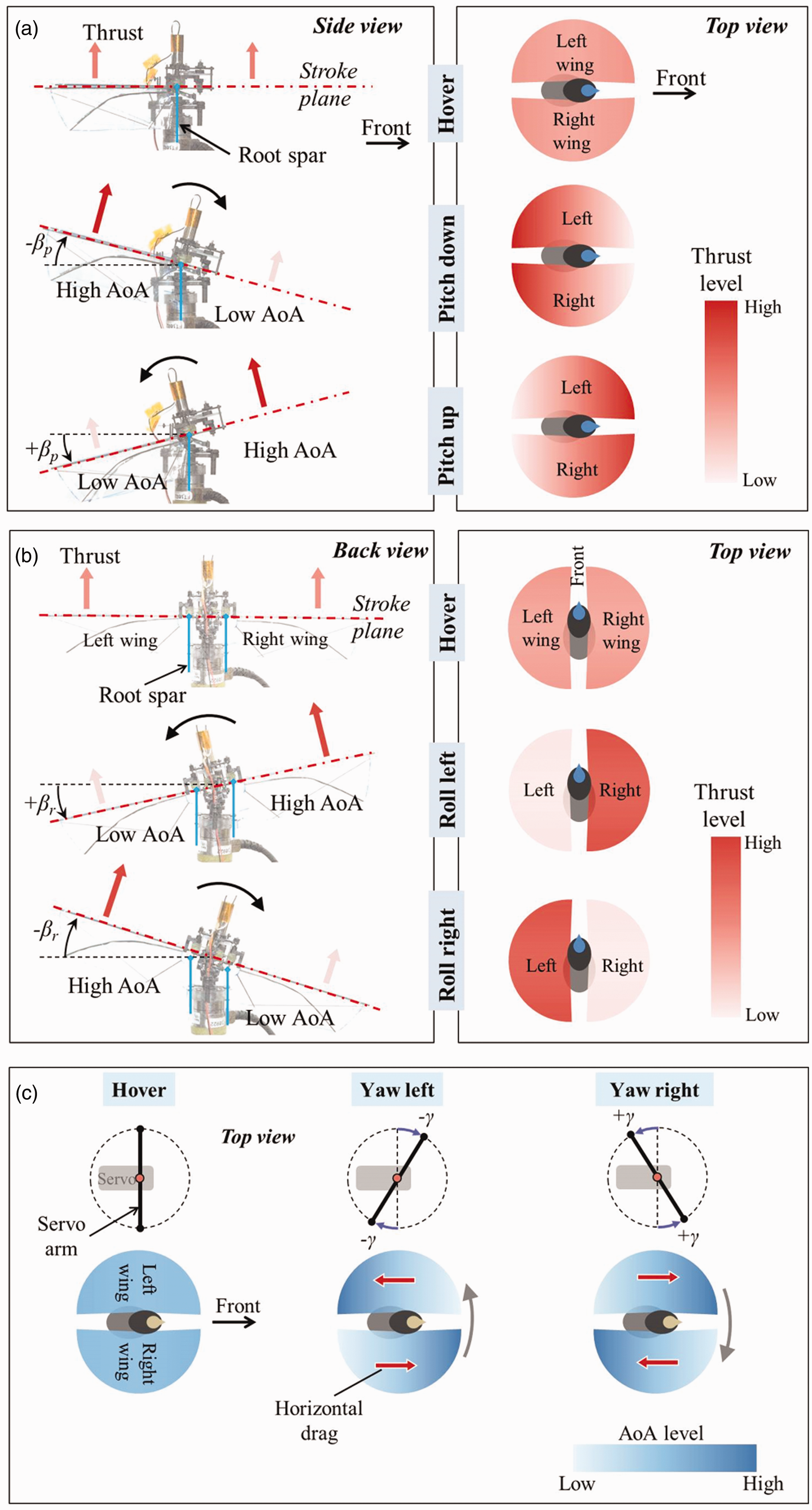
Working principles of the designed control mechanism for: (a) pitch, (b) roll, and (c) yaw controls.
Based on the conceptual design, we fabricated parts for the control mechanism using a 0.8 mm carbon/epoxy panel and installed it in the flying robot as depicted in Figure 3. Pitch and roll controls are actuated independently by two sub-micro LZ servos (0.5 g, microflierradio.com). We tested and found that the sub-micro servos could produce enough torque to tilt the stroke plane for attitude control and stability during flapping motion. Meanwhile, yaw is controlled by modulating wing root spars, which are directly affected by high oscillating flapping forces. Therefore, yaw control mechanism is actuated by a conventional high-torque digital servo (HK-5320, hobbyking.com) weighing 1.5 g.

Prototype of the control mechanism integrated in the flying robot.
Wing kinematics
We used three synchronized high-speed cameras (Photron Ultima APX, 1024 × 1024 pixels, 2000 fps) to capture the wing motion, as shown in Figure 4. The synchronized 2D images captured by the three cameras were inputted to the DLTdv3 program 29 to obtain 3D coordinates of markers placed on the wing, which are referenced from the coordinates of a calibration frame (Figure 4). These 3D coordinates of markers were then converted into sweep angle ψ (the angle between the x-axis and the wing leading edge) and wing rotational angle θr (the angle between the wing chord and the stroke plane) (Figure 4). Procedure to obtain the wing kinematics can be found in more details elsewhere.30–32

Measurement of wing kinematics using three synchronized high-speed cameras and definition of sweep angle (ψ) and rotational angle (θr).
The flapping wing was operated at a flapping frequency of about 23 Hz, which is expected to produce sufficient lift for flight. Because the left and right wings were designed to flap symmetrically, only the right wing was captured for wing kinematics analysis. Figure 5 shows sweep angles and wing rotational angles at 50% wingspan averaged from three flapping cycles for different control inputs of hovering, pitch, roll, and yaw motions. As shown in Figure 5(a), sweep amplitudes are similar for different control inputs. However, time durations of the downstroke and the upstroke are slightly different, especially for pitch and yaw controls due to variation of AoA in each stroke, as shown in Figure 2. Figure 5(b) shows wing rotational angle when the stroke plane is tilted ±15° for pitch control. Because the wing root is constrained, change of the stroke plane causes variation in the wing rotational angle or AoA during downstroke and upstroke for the pitch control inputs, compared to the hovering case. Figure 5(c) plots rotational angles for roll control. For roll-right control, the stroke plane was tilted to the right, causing decrease and increase of AoAs in right and left wings, respectively. By tilting the stroke plane to the left, roll left can be achieved. Figure 5(d) plots wing rotational angles for yaw control when the yaw servo’s arm is rotated for ±20°. We can see that time histories of the rotational angles for pitch (Figure 5(b)) and yaw (Figure 5(d)) controls are similar. This is because wing roots are under the same manner of deflection with respect to the stroke plane. Thus, tilting the stroke plane causes change in the wing rotational angle or AoA, supporting the production of control torque for attitude change.

Time histories of sweep angle and wing rotational angle at mid-span (0.5R) of the right wing: (a) sweep angles, and (b–d) wing rotational angles during (b) pitch control, (c) roll control, and (d) yaw control.
Force and torque generation
To investigate the capability of control torques generation, we set up an experiment using a six-axis load cell (Nano 17, ATI Industrial Automation, USA, force resolution ≈0.3 gf, torque resolution ≈0.0156 N·mm), as shown in Figure 6. We located the load cell close to the location of the robot’s center of gravity (CG). Thus, torques obtained from the load cell can be regarded as those about the CG. We excited the flapping-wing system using an external power supply (E36103A, Keysight, Korea) at a flapping frequency of 23 Hz.
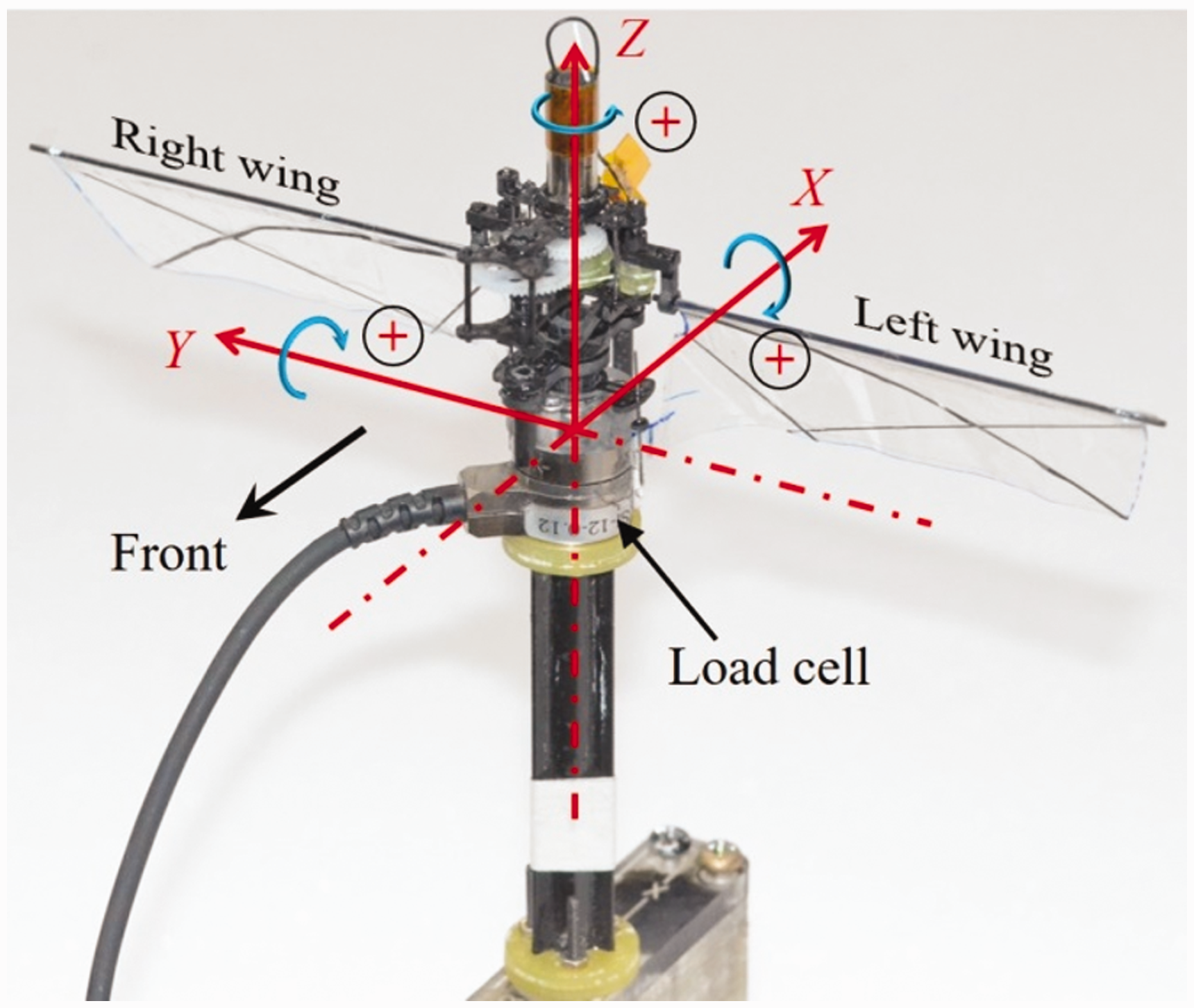
Experimental setup for forces and torques measurement using the load cell Nano 17.
Figure 7 shows forces and torques generated in the three axes for different pitch, roll, and yaw inputs. At 23 Hz, a mean vertical force (Fz) of about 18.5 gf was produced. Changing control inputs (βp) for pitch resulted in linear changes in the horizontal force (Fx) and pitch torque (My). In the range of control input (βp) from –15° (pitch down) to 15° (pitch up), the measured Fx varied from –4.0 gf to 3.1 gf and My varied from –4.2 N·mm to 2.7 N·mm. Without control inputs for hovering condition (βp = 0°), pitch torque of about −0.5 N·mm was generated. This is due to slight vertical misalignment between the mean aerodynamic force center and the load cell. Effect of pitch control inputs on other forces (Fy and Fz) and torques (Mx and Mz) was insignificant. For roll control, changing the control input (βr) from –15° (roll right) to 15° (roll left) resulted in changes of lateral force (Fy) from 2.4 gf to –2.6 gf and roll torque (Mx) from –2.8 N·mm to 2.6 N·mm. A slight decrease in the vertical force was found for a higher roll commend angle. Yaw torque (Mz) is less sensitive to the yaw command (γ) compared to those of pitch and roll commands. For the range of yaw inputs by the tilt of yaw servo’s arm (Figure 2) from −20° to 20°, yaw torque varied from 0.5 N·mm to −0.3 N·mm (a reference of 0.06 N·mm at hovering condition). Thus, the proposed control mechanism can produce reasonable control torques to be implemented in the flying robot.
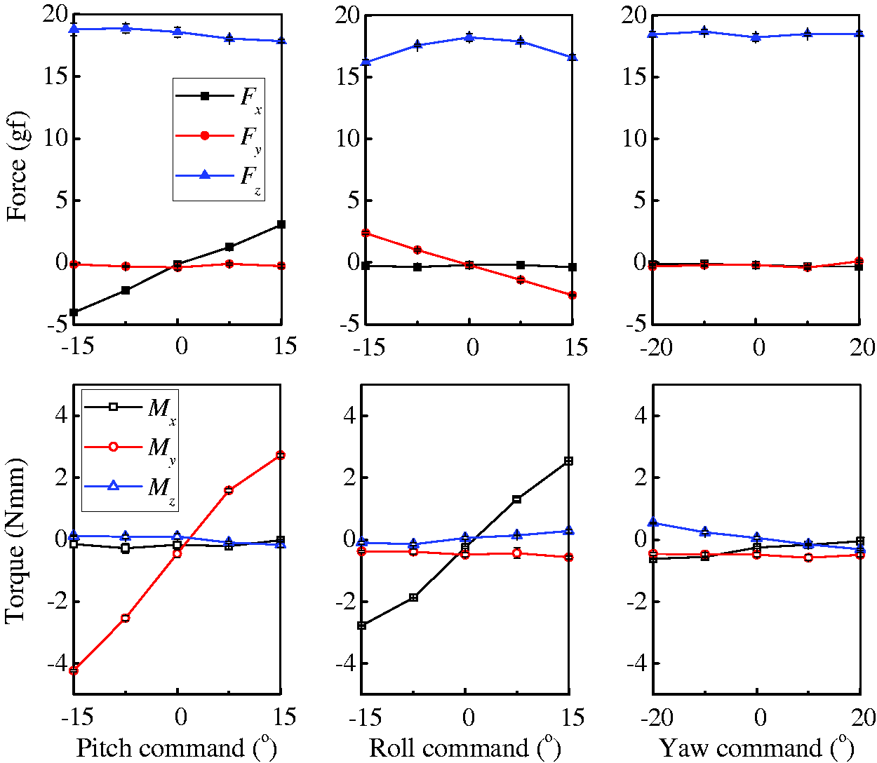
Generation of forces and torques in three axes for a range of control inputs.
Attitude stabilization
For attitude control and stabilization, a custom-built 1 g, four-layer control board (23 mm length × 17 mm width) was mounted onboard. The board consists of a microprocessor ARM Cortex-M4 32-bit STM32L432KC, a 9-axis MPU-9250 consisting of three-axis gyroscope, accelerometer and magnetometer (AK8963C), a 2.4GHz transceiver nRF24L01+, and power regulators, as shown in Figure 8(a). Due to magnetic field interference produced by surrounding high current lines, servos, and DC motor, we used an extensional magnetometer located at the tip of front leg apart from interference sources (Figure 9) instead of the one integrated in the control board to ensure stable measurement.
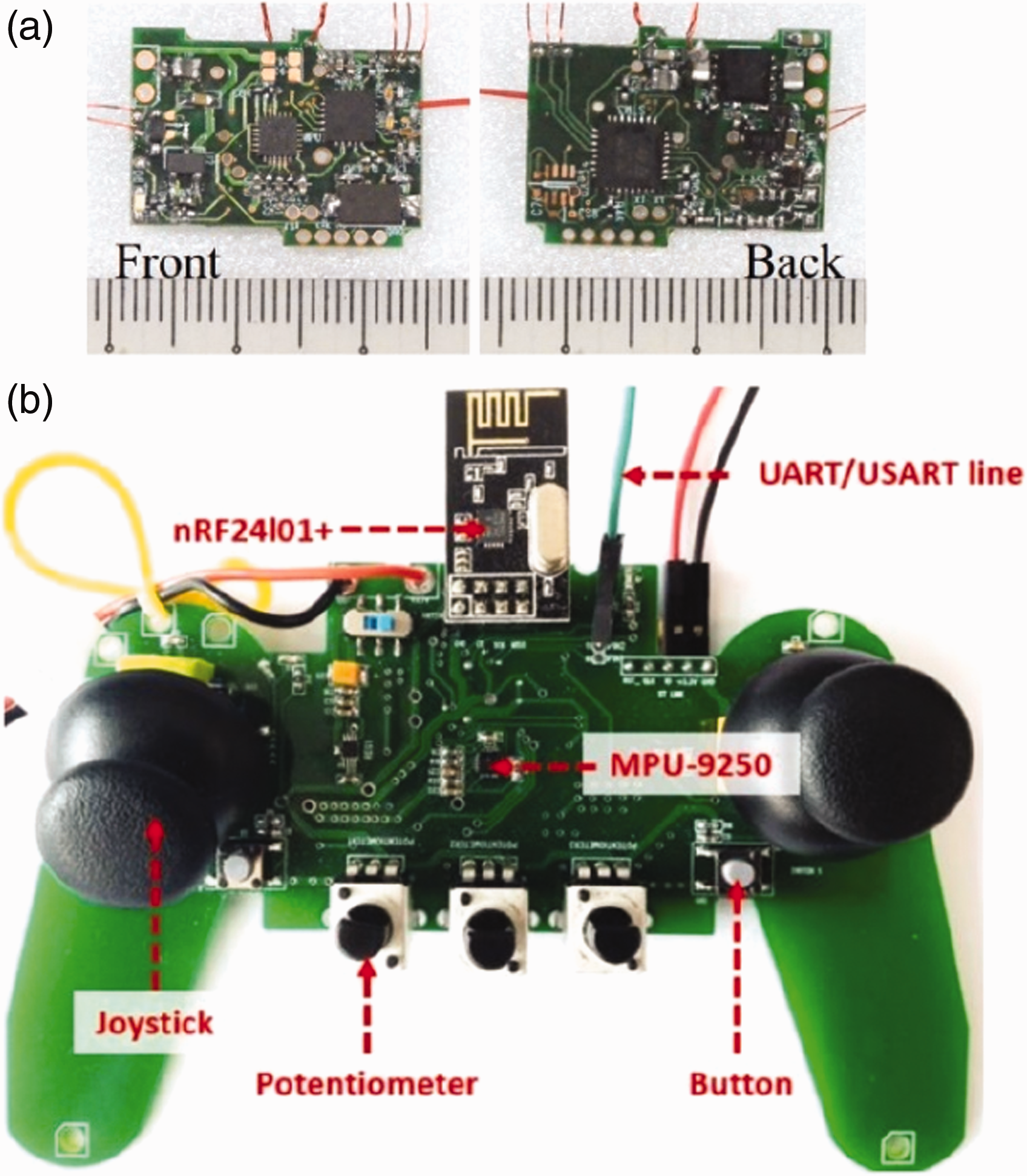
(a) Custom-built flight control board used in the flying robot and (b) remote control.

Attitude control loop for KUBeetle-S robot.
In addition, we custom built a remote control with the same transceiver as control board and similar parts used in a conventional remote control such as joysticks, potentiometers, and buttons, as shown in Figure 8(b). Furthermore, an IMU was added to optionally allow control by motion when selected. The remote control works as control command transmitter and flight data receiver at the same time. Flight data are sent to a computer in real time for observation and recording. Data rate depends on radio frequency signal stability and data size, which can be modified accordingly. With 14-byte payload data transmission and 115,200 baud rates UART/USART communication to the computer, the data rate is around 100 Hz.
Due to inherent instability of tailless robot, a feedback proportional–derivative controller was implemented in the control system to sense the attitudes of the robot that could be determined by roll, pitch, yaw Euler angles (ϕ, θ, ψ, respectively) and angular rates (p, q, r, respectively) about the X-, Y-, and Z-axes, respectively (Figure 9). Accelerometer readings are used to obtain roll and pitch angles. Meanwhile, angular rates are estimated from gyroscope readings. Thus, roll and pitch attitudes can be estimated either by accelerometers or gyroscopes. However, data obtained from accelerometers are strongly affected by vibrations caused by a high flapping motion. On the other hand, gyroscope signals are less sensitive to disturbances, but drift by time. To solve this issue, a combination of low-pass and Kalman filters that could use signals from both gyroscope and accelerometer was used to filter the roll and pitch angles, while a low-pass filter was used to smooth the yaw signal. 33
Flight experiment
The robot named KUBeetle-S with a wingspan of 170 mm and height of 75 mm (Figure 10) weighs about 16.4 g, as shown in Table 1. The driving motor was powered by a two-cell lithium-polymer battery connected in series (7.4 V, 70 mAh). With onboard regulators in the control board, the servos and MPU9250 sensor were supplied by 5 V and 3.3 V sources, respectively. The power inputted to the motor was manually controlled though the power throttle stick.

KUBeetle-S integrated with an onboard control system.
Mass breakdown of the KUBeetle-S.

The KUBeetle-S was demonstrated for free flight to evaluate the effectiveness of the control mechanism. Figure 11 shows composite images of the robot during its flight in the first 30 s after takeoff from the ground. With the battery capacity, the robot demonstrated its successful flight for about 3 min. Figure 12 plots body attitude without heading hold activation. In this case, pitch (θ) and roll (ϕ) angles showed small variations from the reference of 0°. However, since yaw motion was stabilized using gyroscope signal only, it experienced drift during flight. Additionally, yaw control torque was less sensitive to the yaw input, as shown in Figure 7. Therefore, heading direction (ψ) drifted during flight. However, the upright stability of the robot was unaffected by the heading stability. On the other hand, with activation of heading hold using sensing signals from the magnetometer, heading direction of the robot was maintained, although slight oscillations around the reference angle occurred (Figure 13). In conclusion, the flight proves that the attitude control system is successfully implemented in an insect-like tailless flying robot.

Composite images of KUBeetle-S during hovering flight.

Attitude performance of KUBeetle-S during hovering flight without heading hold. Solid and dashed lines denote the body attitude angles and reference angles, respectively.

Attitude performance of KUBeetle-S during hovering flight with heading hold. Solid and dashed lines denote the body attitude angles and reference angles, respectively.
Conclusion
This work introduces a 16.4 g insect-like tailless, two-winged, hover-capable KUBeetle-S robot that can change its stroke plane and wing twist simultaneously for pitch and roll controls and modulate wing root spars asymmetrically for yaw control. The proposed control mechanism, which requires less actuation torques from actuators, is simple and easy for fabrication allowing us to use small actuators to save weight. Measured data proved that the control mechanism could effectively generate reasonable amounts of force and torque for attitude controls. Finally, KUBeetle-S with the implementation of onboard attitude feedback control system successfully hovered and loitered for about 3 min, demonstrating the effectiveness of the proposed control mechanism.
Footnotes
Declaration of conflicting interests
The author(s) declared no potential conflicts of interest with respect to the research, authorship, and/or publication of this article.
Funding
The author(s) disclosed receipt of the following financial support for the research, authorship and/or publication of this article: This research was partially supported by the 2018 KU Brain Pool Program of Konkuk University, Korea.