
Abstract
Hovering flies are able to stay still in place when hovering above flowers and burst into movement towards a new object of interest (a target). This suggests that sensorimotor control loops implemented onboard could be usefully mimicked for controlling Unmanned Aerial Vehicles (UAVs). In this study, the fundamental head-body movements occurring in free-flying insects was simulated in a sighted twin-engine robot with a mechanical decoupling inserted between its eye (or gaze) and its body. The robot based on this gaze control system achieved robust and accurate hovering performances, without an accelerometer, over a ground target despite a narrow eye field of view (±5°). The gaze stabilization strategy validated under Processor-In-the-Loop (PIL) and inspired by three biological Oculomotor Reflexes (ORs) enables the aerial robot to lock its gaze onto a fixed target regardless of its roll angle. In addition, the gaze control mechanism allows the robot to perform short range target to target navigation by triggering an automatic fast “target jump” behaviour based on a saccadic eye movement.
Keywords
Introduction
Making Unmanned Aerial Vehicles (UAVs) autonomous is likely to be a key research subject for the next 10 years. To achieve this autonomy, one of the most crucial steps is stabilizing the attitude of aerial vehicles. This objective has been classically achieved using an Inertial Measurement Unit (IMU) composed of rate gyros, accelerometers and magnetometers ([1–3]). But IMUs often have to be combined with other sensors to estimate the position of the UAV without drifts. A GPS has been used, for example, to remove the bias from the pose estimates in outdoor applications ([4–6]). Many strategies involving vision and IMU combined have been adopted for indoor applications because they work efficiently in GPS-denied environments. For example, [7] used an external trajectory device yielding very fast dynamics, which was able to accurately measure both the position and the attitude of a robot equipped with markers. Likewise, [8] used a simple external CCD camera to measure the positions of two LED markers onboard a quadrotor. Although external visual sensing devices of this kind are quite accurate, their visual computational resources often have to be provided by a ground-based host computer. In other studies, the visual sensor was implemented onboard a robot, which was stabilized using two elliptic markers (one placed under the robot and the other in front of it) to determine its attitude and position ([9]). Five markers with a specific geometry were used by [10] to estimate the robot's yaw and position, while an IMU gave the robot's attitude and angular velocities. Another particularly cheap solution ([11]) comprised using a Wii remote sensor (Nintendo) to control a hovering vehicle, while the pitch and roll were measured by an IMU. Another solution ([12]) consisted of merging a five DOF estimation provided by a monocular camera with a gravity vector estimation provided by an IMU to achieve take-off, hovering and landing of a quadrotor. Successful control of a hovering quadrotor was achieved by cancelling the linear velocity based on optic flow measurements ([13], [14]). Optic flow was also used to estimate the altitude and the forward speed of an airborne vehicle ([15]). The robot's attitude has usually been determined in these studies by means of an IMU combined with accelerometers compensating for the drift. However, the authors of several studies have used small or panoramic cameras to determine the robot's attitude ([7]). Visual servoing was recently applied to stabilize a hovering quadrotor equipped with a fixed camera facing a ground-coloured target ([16]). When this approach was tested under natural outdoor conditions, its vision-based hovering accuracy was found to range between −2m and 2m. In [17], a monocular camera and computer vision with high delays was used to avoid drift obtained with a simple IMU pose estimation. A camera is also used in [18] as a dual-sensor to achieve a drift-free hover and perform obstacles avoidance on a quadrotor.
In our bio-inspired minimalistic framework, a new control strategy was developed, which consists of using only three sensors:
an optical angular position sensing device with a small Field-Of-View (FOV) of only a few degrees, which is able to locate the angular position of a ground target with great accuracy ([19], [20]) a low-cost rate gyro a simple proprioceptive sensor used to measure the eye orientation in the robot's frame.
Using a decoupled eye onboard an UAV greatly reduces the computational complexity because a narrower FOV could be used, meaning fewer pixels were needed. In a previous robotic study ([21]), a decoupled eye is classically used as an observation device to track a target and compensate for the UAV displacements around this target. The latter was successfully tracked by an autonomous helicopter, the position and attitude of which were determined using a combination of GPS and IMU. In the present study, it was proposed to use the robot's own gaze (i.e., the orientation of the eye in the inertial frame) as a reference value in order to determine its rotations and positions.
An eye with a restricted FOV of only a few degrees (like a kind of fovea 1 ) was adopted here for the following main reasons:
a small FOV means that very few pixels have to be processed because a small FOV can be obtained by selecting a small Region Of Interest (ROI) a small ROI means a high frame rate a fovea makes it possible to greatly reduce the computational complexity of the visual processing algorithms, as described in [22]. Therefore that tiny, low-cost, low consumption microcontroller can be implemented onboard the robot.
The robot's eye was taken to be a visual Position-Sensing Device (PSD), which is able to locate an edge (or a bar) accurately thanks to its small FOV (here, FOV = ±5°, in opposition to a classical FOV of ±25°). This visual sensor was endowed with hyperacuity ([23]), i.e., the ability to locate a contrasting target with a much better resolution than that dictated by the pixel pitch. The implementation of this kind of hyperacute sensor visual sensor was described by previous authors ([19, 20, 24–26]).
The simulated robot and its decoupled eye are described in Section 2 along with the nonlinear dynamic model. The Processor-In-the-Loop (PIL) system used to perform the simulations was also described in this section. The original nonlinear observer presented in Section 3 estimates the linear speed, the position, the attitude (on the roll axis only in this paper), and the rate gyro's bias. Then the gaze controller as well as the whole robot controller based on these estimations is described in detail. In Section 4, a new navigation strategy for aerial robots in terms of automatic target to target navigation based on a saccadic flight is outlined. Lastly, the advantages of using a decoupled eye with a gaze control strategy are discussed before the conclusion.
System overview
In this part, we will describe first the PIL system and the custom toolchain we developed to perform the robot's simulation. Then we will present how the biology has inspired our approach and finally we will present the twin-engine robot's model.
Processor-In-the-Loop (PIL) simulation
All the simulations presented in this study were performed using an Processor-In-the-Loop (PIL) system. Figure 1 shows the environment and the links existing between the host computer and the embedded processor board. The host computer simulates the robot's dynamics in real time and monitors the computations performed by the embedded autopilot board which controls the robot.
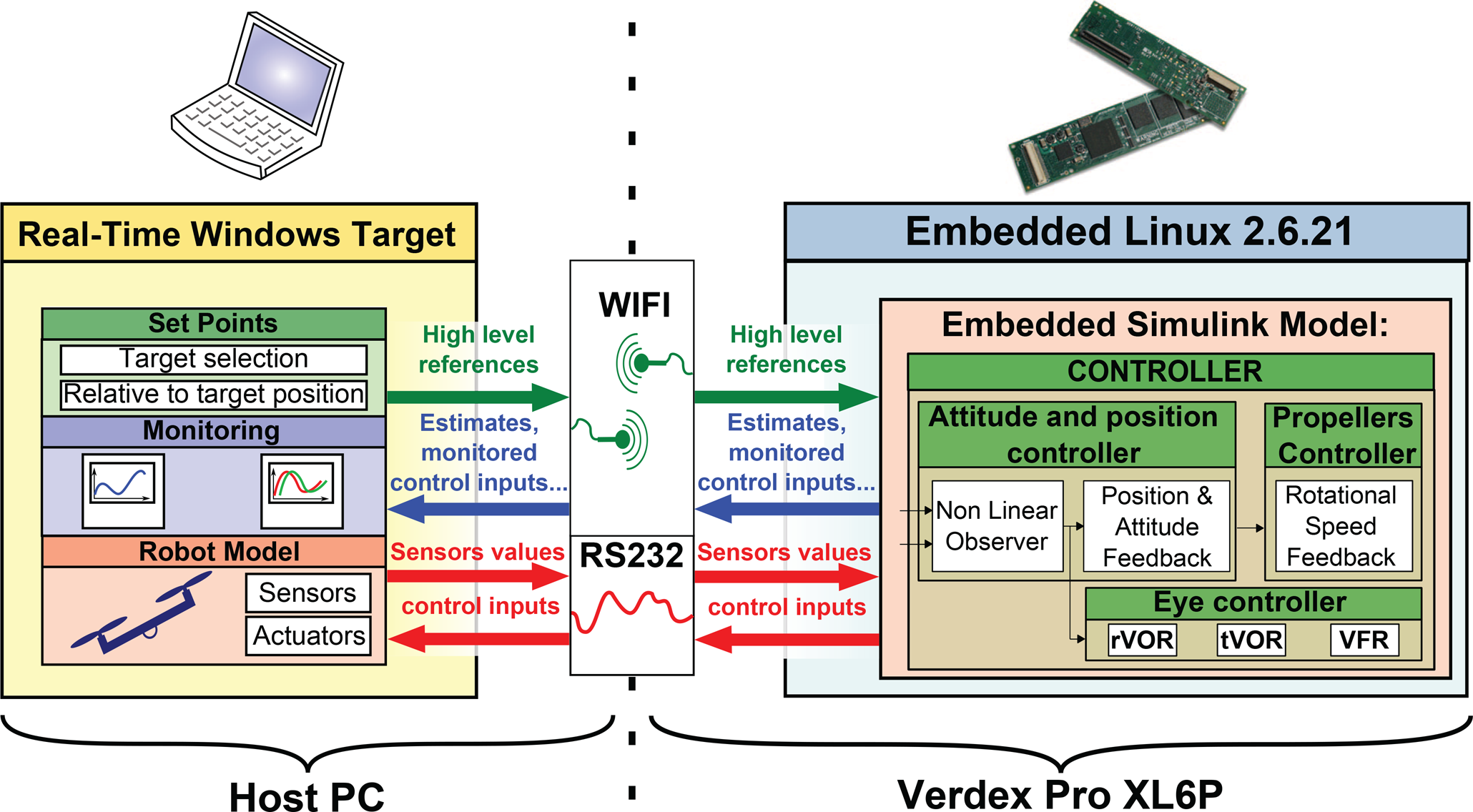
Description of the PIL structure. The robot and the ground station are connected by two links. A wireless link (wifi) monitors the control board computations (the Gumstix VERDEX Pro XL6P), emits the Linux commands and the high-level set-points. A serial link currently emulates the future connection between the high-level control board and the low-level control board of the robot.
In its future version, our robot, a quadrotor, will be equipped with a Gumstix, which is a Linux-based Computer-On-Module (COM). This processor board is equipped with an XScale-PXA270 processor cadenced at 600MHz with 128MB of DRAM and 32MB of Flash memory. This powerful micro computer was chosen to make our robot fully autonomous in terms of computational resources. In addition, the Gumstix can be easily managed via a wifi connection and a console application (such as PuTTY) from the host computer.
Rapid prototyping tool: from Simulink to Gumstix
The novel fast prototyping tool we have developed can be used to automatically and easily download a Simulink model (containing the controllers and the observers in our case) onto the autopilot board. This development toolchain uses a user friendly interface, such as Matlab Simulink, to execute in real-time digital controllers designed in the Simulink environment. This novel automatic code generation tool makes the implementation of a digital control system considerably easier and faster because:
it generates and compiles a bug-free C code it gives block-level access to on-chip peripherals (wifi, serial connections, etc.) it can be used to directly design systems using floating-point system design, simulation and scaling procedures thanks to the 32-bit FPU of the Gumstix (it also handles all the fixed-point data).
Biology as a source for new robot's abilities
As shown in figure 2, the robot consists of a twin-engine aerial robot with two degrees of freedom. This robot was considered to fly at a constant altitude H. It is therefore able to rotate freely θ r around its roll axis, translate along the horizontal axis X and a third degree of freedom enables the eye to rotate with respect to the robot's body (θ er ) thanks to a mechanical decoupling between the eye and the body. The eye's orientation is assumed to be finely controlled by a very fast, accurate servomotor.
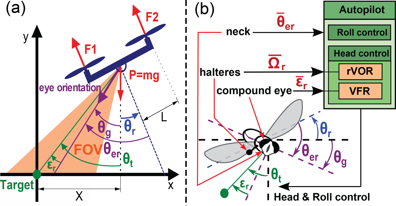
Similarities between the hovering robot with a decoupled eye (a) and the fly (b). These two dynamic underactuated systems are able to measure their body's rotational speed Ω r by means of a rate gyro (in the case of the robot) and halteres (in that of the fly) and to locate a contrasting target θ t placed in a small part of their FOV. The fly has no less than 23 pairs of neck muscles with which to stabilize its gaze θ g , whereas the simulated robot controls the angular position of its eye θ er by means of a small actuator (e.g., a servomotor). In this figure, the fly and the robot are hovering over a target placed on the ground.
As discussed in [27] and [28], the design of our hovering robot and its sensing abilities results from our bio-inspired approach where biology is a source of new ideas for implementing new mechanisms and control strategies. In this sense, our sighted robot with its drifting rate gyro, its proprioception and its visual sensor with a small FOV accounts for key mechanisms observed in flying insects in terms of sensing abilities (see [29]), gaze stabilization (see [30–32]), flight behaviour ([33–36]) and target localization ([37]). The following main similarities between the robot and the fly shown in figure 2 are listed below:
In the first part of this study, the robot was assumed to be hovering above a single stationary ground target. As shown in figure 3 and 4, the robot's roll (θ r ) is controlled by applying a differential rotational speed to the propellers. [15], [11] and [8] have established that the altitude control can be completely decoupled from the roll and lateral control in systems belonging to the class of planar Vertical Taking Off and Landing (VTOL) aircraft. It is therefore assumed here that the hovering altitude of the robot is constant and equal to H. To control the position of this underactuated robot, it is necessary to adjust the attitude around the roll axis. The robot's equilibrium therefore corresponds to a null roll angle, θ r = 0°.
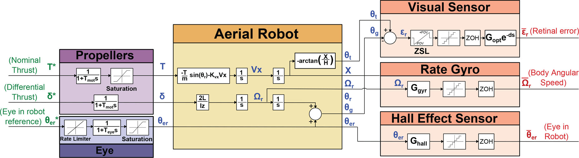
Simplified block diagram of the robot. Due to the mechanical decoupling between the robot's body and its eye, the latter can be described as an independent system receiving its own reference input signals θ er *.
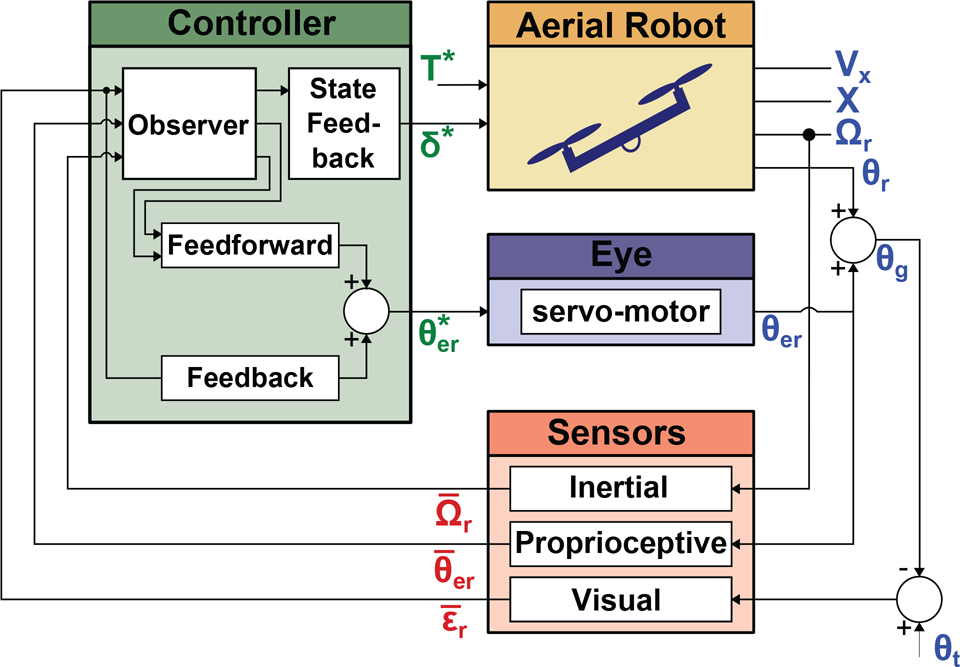
Block diagram of the complete system. The robot is equipped with a rate gyro measuring the rotational speed around the roll axis and a decoupled eye locked onto a distant target. The green variables are the control input signals, the blue ones are the physical variables of interest, and the red ones correspond to the measurements.
Figure 3 gives an overview of the robot's control architecture, which is based on an observer combined with a state-feedback controller controlling the robot's attitude and position. Figure 3 presents the mechanical decoupling between the eye and the robot by showing that the robot and its eye receive separate reference input signals (T*, δ* and θ er *).
The following notations and angles will be used in what follows:
θ
t
: angular position of the target relative to the robot's position in the inertial reference frame. θ
r
: the robot's roll angle. θ
er
: eye-in-robot angle, given the gaze direction in the robot's frame. This angle is mechanically constrained to a maximum value: |θ
er
| < θer_MAX. θ
g
: gaze direction in the inertial frame θ
g
= θ
er
+ θ
r
. ε
r
: retinal error detected by the visual sensor, defined by ε
r
= θ
t
− θ
g
. X: robot's position along the horizontal axis in the inertial frame. Vx: robot's speed along the horizontal axis in the inertial frame. Y: robot's hovering altitude in the inertial frame. Y was taken to be constant (Y(t) = H ∀t). Ω
r
: the robot's rotational speed.
The estimated values will be denoted from now on by an additional hat (e.g.,
The nonlinear dynamic model of the robot was developed classically using rigid body equations, and simplified to account for the simple case where the robot can perform only roll rotations and horizontal translations:
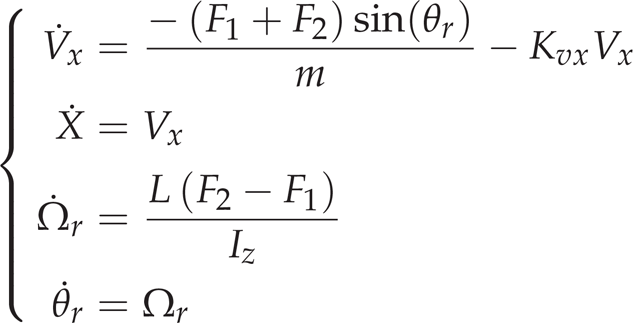
where L is the distance between the robot's centre of mass and the propellers, Iz is the inertial momentum around the roll axis, F1 and F2 are the thrust generated by propellers 1 and 2, respectively, and Kvx is the drag coefficient which is assumed to be constant.
The eye's dynamics are modelled as a first order transfer function cascaded with a rate limiter corresponding to the maximum rotational speed. The mechanical constraints (the angular course) are modelled in terms of the saturation (see the block named “Eye” in figure 4).
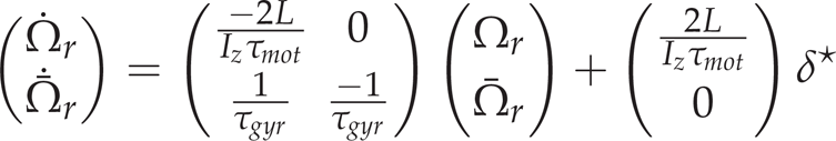
For greater clarity, the stabilization of the robot with its decoupled eye was decomposed into two independent problems. Stabilization of the robot's attitude and position are handled by a high-level controller (see subsection 3.5) yielding a reference rotational speed (Ω r *), which is fed to the low-level propeller speed controller. The latter consists of an internal loop which aligns the robot's rotational speed Ω r faithfully with the reference speed Ω r * (see subsection 3.4).
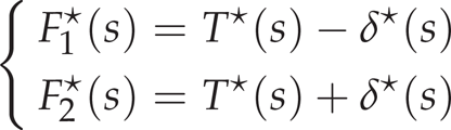
The thrust generated by the two propellers is classically composed of a nominal thrust T and a differential thrust δ. The nominal thrust (T*) counteracts the gravity and the differential thrust (δ*) generates the torque responsible for roll rotation. The propellers were assumed to be controlled by adjusting their thrust as follows:
The dynamics of the two propellers were modelled in the form of a first order system with a time constant τ
mot
(see table 2). The transfer function F1,2(s) is therefore given by
This study is part of a larger project in which robust, accurate and fast hovering flight is achieved mainly on the basis of a gaze control system. For example, [25] developed a “steering by gazing” strategy to maintain the gaze of a robot oriented toward a target. In many previous studies ([45], [46]), the robot's attitude was determined using an Inertial Measurement Unit (IMU) including a rate gyro, accelerometers and/or magnetometers, and a fixed camera ([47–49]). In this paper, an alternative approach is presented for answering the following question: how can a hovering robot be accurately stabilized by means of only a rate gyro and a visual sensor? Recent studies on the hoverfly ([36]) have suggested that efficient solutions to this problem do exist and that the gaze control system is certainly one of them. As a result, the present robot's attitude and position, and the rate gyro's bias, are now determined on the sole basis of the robot's measured angular speed
In this part, we propose explaining how the eye and the hovering controller were designed, and how they interact with each other.
The nonlinear observer
The nonlinear observer is the cornerstone of the present hovering strategy, as shown in figure 5. By combining the robot's eye orientation (

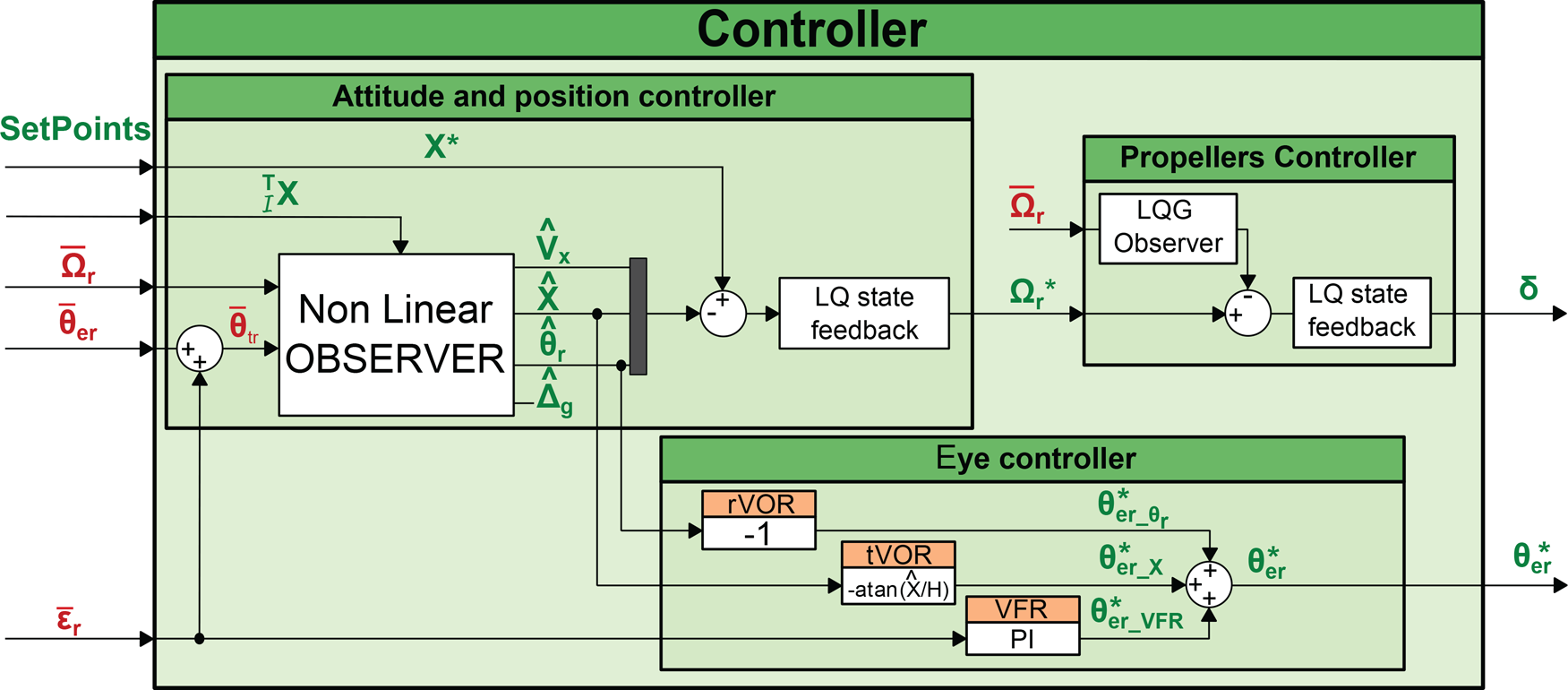
Block-diagram of the controller. The nonlinear observer determines the attitude of the robot on the sole basis of the angular speed and eye orientation measurements. The eye controller is based on three Oculomotor Reflexes (ORs), which keep the eye locked on the target regardless of the translational or rotational disturbances that may occur. Measured signals are presented in red and control input signals are presented in green. Note that the set-point
As the robot's rotational speed measurement (

where
The implementation of a nonlinear observer was based on the strongly nonlinear equation giving the evolution of the linear speed Vx (see equation (4)) and the nonlinear output
Rate gyros always have a bias, resulting in a drift in the attitude estimation if they are not filtered and fitted. Classical methods ([3, 45, 46, 50, 51]) are based on accelerometers to determine the gravity direction, and/or magnetometers to perform magnetic field measurements, and compensate for the rate gyro bias. The original method presented here relies, as occurs in insects, on vision and proprioceptive sensors (specifying the eye's orientation
The rate gyro's bias can be defined as follows:


where Ω r is the actual rotational speed, Δ g is the rate gyro's bias, and μ is an unknown centred noise.
The eye's controller keeps the gaze locked onto a target placed on the ground. Since the field of view is very small, the closed loop gaze system has to act very fast and efficiently. The requisite efficiency is achieved using a bio-inspired approach, involving a combination of three complementary oculomotor reflexes:
A rotational vestibulo-ocular reflex called the rVOR, which has to counteract the effects of all the rotations performed by the robot. This reflex yields the signal θer_θ
r
*, which is simply the opposite of the roll angle A translational vestibulo-ocular reflex called the tVOR compensates for the effects of any robot's translations in the retina. The output signal θ
er_X
*, based on the robot's position A visual fixation reflex called the VFR, consists of a visual feedback loop with which any retinal signal errors ε
r
are cancelled by controlling the eye's orientation θ
er
via the control input signals θ
er_VFR
* (see figure 5).
The VFR reflex plays a key role here. It is the main reflex serving to track the target under all conditions. Thanks to this reflex, the robot is able to:
hover “robustly” above a target, reject any lateral disturbances resulting from gusts of wind by quickly correcting the eye's orientation, which is not possible if the robot has no decoupling, because of its relatively large inertia.
The VFR controller consists of a simple proportional integral controller, which keeps the retinal error close to 0°. This controller yields a reference angle (θ er_VFR *) in order to contribute to the eye's orientation, see equation (7). In short, this reflex is responsible for target tracking in every situation, which is the first step towards hovering robustly and accurately determining the robot's attitude and position.
The VOR is composed of a combination of two reflexes keeping the target in the FOV even if the robot is moving. VORs, which were directly inspired by the visual processes occurring in insects, compensate for two kinds of robot movements:
The reference angle θ er * (see figure 5), which therefore results from the joint contribution of three reflexes (rVOR, tVOR and VFR), can be expressed as follows:

The VORs were used as feedforward control signals cancelling the movements perceived by the robot (thanks to the gyro and the eye-in-robot angle). Additionally the VFR is used here as a feedback control signal cancelling any undetected movements and the modelling errors present in the feedforward terms. Simulation results and discussions about the efficiency of theses reflexes could be found in our previous works ([52] and [53]).
The rotational speed of the robot is used by the attitude and position controller as an input control signal to stabilize the robot and achieve the desired position (figure 4). In this way the rotational speed inner loop makes the robot faithfully adopt the speed rotation set-points (Ω r *) imposed by the attitude-position controller (see subsection 3.5). It was assumed here that the propellers are driven directly by the thrust, which can be deduced from the propeller's rotational speed in line with equation (8). The rotational speed is therefore controlled by a simple differential thrust between the two propellers.
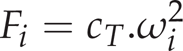
where Fi is the thrust generated by the propeller i, ω i is the rotational speed of the propeller i, and cT is the thrust coefficient, which can be identified using static thrust tests.
In order to account more satisfactorily for the rate gyro's dynamics, a classical LQG controller-observer structure was chosen instead of a simple PID. The state space representation for the rotational speed loop, including the gyro dynamics, can therefore be written:
where Ω
r
is the actual roll rotational speed and
The closed loop time response obtained for Ω r was less than 20ms, and the differential control noise was less than 2%.
The position and attitude controller were implemented using LQR methods and the estimated states (
The LQR state feedback was designed for the system (1) linearized around the origin with the equilibrium control input Ω req = 0. To cancel the steady state error, an integral term was added to the position error.
New outlooks provided by the hovering by gazing control strategy
In previous studies carried out at our laboratory ([52] and [53]), we demonstrated that a robot equipped with a decoupled eye (denoted D-EYE) was able to reject lateral and rotational disturbances better than the same robot with a fixed eye (denoted F-EYE) even if the field of view of the decoupled eye robot is smaller.
The implementation of a decoupled eye onboard an aerial vehicle also opens up new perspectives:
it enables a robot to finely control its horizontal position with respect to the target without being given any explicit information about it position by an external camera, a motion capture system, or a GPS as occurs in more classical systems, it enables a robot to perform shifted hovering with respect to the target. This point has interesting consequences regarding the robot's disturbance rejection ability. More generally, the robot is therefore not constrained to stay in a small restricted area around the target (see subsection 4.1), it enables a robot to jump from one target to another by simply triggering a saccade towards the new target (see subsection 4.2). This provides to the robot the ability to follow a specific trajectory based on various targets forming a path.
Shift hovering
The following discussion demonstrates that the decoupling allows for hovering not only above a target but also near a target. Let us start by defining the Maximum Lateral Disturbance (MLD):
Figure 6 shows the ability of the F-EYE robot with an FOV of ±25° and that of the D-EYE robot with a 5-fold smaller FOV (±5°) to reject lateral disturbances. From this figure, it is possible to determine the MLD corresponding to each robot (F-EYE robot and D-EYE robot):

a) Ground resolution and Maximum Allowable Disturbances (MLD). Thanks to the gaze orientation of the D-EYE robot, the MLD increases with the absolute value of the position (X). b) The Maximum Lateral Disturbance (MLD) on both sides depends on the robot's position. The grey background describes all the positions which cannot be achieved by the F-EYE robot without completely losing sight of the target. In the F-EYE robot, any increase in the MLD on one side will inevitably result in a corresponding decrease on the other side, whereas the MLD of the D-EYE robot increases on both sides in proportion to the robot's distance from the target. This figure was plotted with a F-EYE robot featuring a ±25-° FOV and a D-EYE robot featuring a ±5-° FOV and a maximum ocular angle ±80-° (θ erMAX ).


When hovering perpendicularly above the target, the F-EYE robot benefits from its large FOV and can reject a 93-centimetre MLD, whereas the F-EYE robot can cope with an MLD of only 17.5 centimetres due to its smaller FOV. However, by shifting the robot's horizontal position away from the target, it is possible to greatly increase the D-EYE robot's MLD rejection capacity, which becomes larger than that of the F-EYE robot after simply making a 2-m lateral shift. This simple strategy therefore makes it possible to overcome the problem focusing on the trade-off between the width of the FOV and the MLD. Even with its 5-fold smaller FOV, the D-EYE robot can reject much larger MLDs than the F-EYE robot. In addition, unlike the F-EYE, the decoupled eye enables the D-EYE robot to reject disturbances of practically the same amplitude on both sides (right and left).
One of the main advantages of the novel strategy consisting of shifting the robot laterally with respect to the target focuses on the Maximum Lateral Disturbances (MLD) that can be rejected. From figure 6, it can be seen that the F-EYE robot with a ±25-° FOV cannot even achieve a 2-m shift without losing sight of the target. Unlike the F-EYE robot, the D-EYE robot with a ±5-° FOV decoupled eye hovering at 2m and offset by 2m from the target can reject both right and left lateral disturbances of up to 38cm while keeping a positioning accuracy of more than 1cm.
A last useful advantage of the decoupled eye is its ability to make a change of target. For example, when the robot hovers above a first target, a very quick eye rotation (similar to a catch-up saccade) is generated to make the robot's eye “jump” to a second target, the position of which is known. A catch-up saccade is one of the four types of eye movement (saccadic, smooth pursuit, vestibulo-ocular reflex and vergence) used to track a trajectory. Catch-up saccades occur in humans when the smooth pursuit system is not sufficiently fast to track a moving target ([54]).
In this study, this mechanism was used first to make the robot shift from one target to another. Like the steering by gazing strategy ([25]), the aerial robot will move toward the target at which its gaze is looking.
Notations and implications:
Here we define some notations used to distinguish between the variables used in the various reference frames:
For example,
Three frames of reference were therefore used in this study:
the Robot's frame of reference, denoted R, the Inertial frame, denoted I, the Target's frame, denoted T.
The relation between the estimated robot's position in the inertial frame, the estimated robot's position in the target's frame and the target's position in the inertial frame can be written:

where

where
To make the robot shift from one target to another, a simple change of variable suffices. The previous value of the target's position is then replaced by the new one. The coordinates of the new target just need to be updated as follows:


where Δt corresponds to the nonlinear observer's sampling time and
The eye's “jump” (or saccade) is then expressed by changing the value of the feedforward term θ
er_x
*, which is written with the new notation:
Once the target's new coordinates have been specified, the robot immediately changes its eye orientation and re-positions itself appropriately with respect to the reference

a) Estimation of the position and the corresponding tracking expressed in the different frames of reference. b) Evolution of the eye angle. The updating of the target position described in equation (15) involves a jump in the feedforward term θ er_X * (red curve), which triggers the change of target. c) Retinal error during the target jumping phase. It takes only 0.13s for the eye to lock the new target in its narrow field of view. Therefore, the new target enters into the FOV 0.13s after the target change was asked. Figure 8 shows more precisely the retinal error signals during a target jumping.

Evolution of retinal error during a target jumping. The blue line describes the actual retinal error, and the red one corresponds to the measured retinal error which includes the sensor quantification, discretization, dyamics, internal delay and the eye's limited FOV (see table 2). Here, the new target is locked in less than 0.13s and is kept locked into the FOV. In addition, the retinal error is kept under 1.4° in less than 0.15s (∊ r < 1.4°) and under 0.2° in less than 0.7s.

The robot's attitude during “target jumping”. Plots of the UAV's position and attitude were sampled at 20Hz. For the sake of clarity, the various sequences have been shifted vertically, but the altitude H remained constant throughout all the jumping sequences. At t = 0s, the robot shifted one metre to the right with respect to the target 1. At t = 5s, the robot made a change of reference target and moved to a point one metre to the right of the target 2. Lastly, at t = 10s, the robot moved to a point one metre to the right of the target 3, the new reference target.
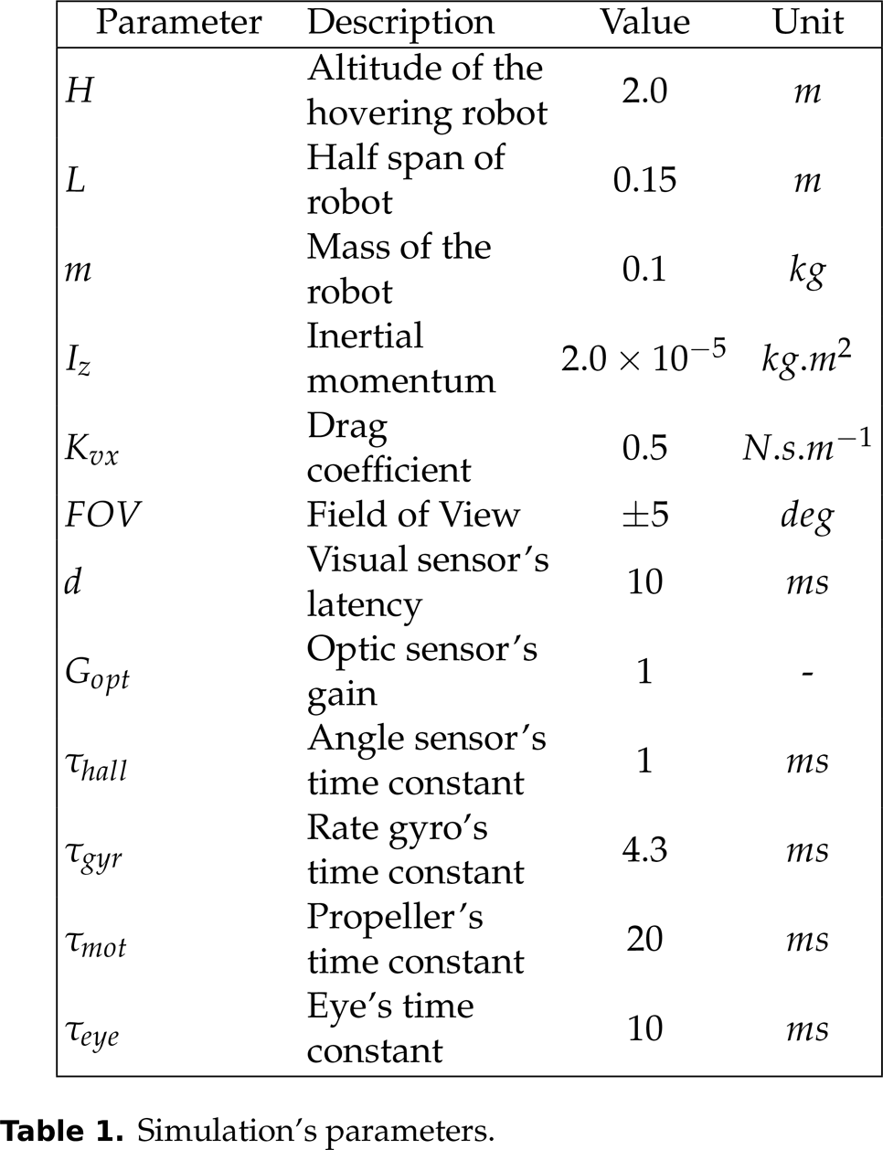
Simulation's parameters.
Sensors' and actuators' characteristics.

The following scenario was simulated in figures 7 and 9:
step 1: the robot made a 1-m lateral shift with respect to the target step 2: after 5s, the robot jumped to target 2 and the previous lateral shift with respect to the target was maintained (the figure 8 shows only the eye jump occurring at t = 5.0s) step 3: after 5s, the robot jumped to target 3
We therefore have:
In conclusion, thanks to the fast eye dynamics, the “eye jump” is performed very quickly because the new target is locked by the robot's eye in less than 0.13s, as shown in figure 8. Once this new target is locked, the robot's body automatically reaches the desired relative to target position
Here we summarize the advantages of having a decoupled eye with a small FOV:
where

In this paper, a simulated hovering aerial robot equipped with a decoupled visual system and a bio-inspired strategy of stabilization are presented. The control strategy depends on oculomotor reflexes providing accurate gaze stabilization, which greatly improves the robot's ability to reject large lateral and rotational disturbances. The gyro's data are unbiased using the orientation of the gaze given by a proprioceptive sensor. This novel approach was tested using a PIL development toolchain which allows easy programming and execution in real-time using the Simulink autopilot on the embedded Gumstix COM. In addition, the saccadic eye movements enables the robot to navigate along a travel path defined by several successive targets. As a conclusion, the practical uses of a decoupled eye go far beyond the stabilization of a hovering robot: it opens up promising avenues for controlling the 3-D position of a robot by anchoring its gaze onto particular objects of interest. In a future study, the method presented here will be implemented onboard a small fully autonomous quadrotor with six degrees of freedom.
Footnotes
7.
The authors would like Jessica Blanc for correcting the English manuscript. This work was supported by CNRS, Aix-Marseille University and the French National Research Agency (ANR) with the EVA, IRIS and Equipex/Robotex projects (EVA project and IRIS project under ANR grant numbers ANR608-CORD-007-04 and ANR-12-INSE- 0009, respectively).
Acronyms
1
The fovea is a part of the eye which is responsible for sharp central vision, useful where visual detail is of primary importance.