
Abstract
This paper describes the results of a six-year project aiming at designing and constructing a flapping twin-wing robot of the size of hummingbird (Colibri in French) capable of hovering. Our prototype has a total mass of 22 g, a wing span of 21 cm and a flapping frequency of 22 Hz; it is actively stabilized in pitch and roll by changing the wing camber with a mechanism known as wing twist modulation. The proposed design of wing twist modulation effectively alters the mean lift vector with respect to the center of gravity by reorganization of the airflow. This mechanism is modulated by an onboard control board which calculates the corrective feedback control signals through a closed-loop PD controller in order to stabilize the robot. Currently, there is no control on the yaw axis which is passively stable, and the vertical position is controlled manually by tuning the flapping frequency. The paper describes the recent evolution of the various sub-systems: the wings, the flapping mechanism, the generation of control torques, the avionics and the PD control. The robot has demonstrated successful hovering flights with an on-board battery for the flight autonomy of 15–20 s.
Introduction
The amazing agility of insects and hummingbirds has always fascinated the humans and, over the past 40 years, biologists have gradually uncovered the complex unsteady aerodynamic mechanisms leading to extraordinary aerodynamic forces generated by their flapping wings.1–4 Simultaneously, the extreme miniaturization of avionics has made possible to consider building robots mimicking the behavior of insects and birds. This, together with the explosion of the demand in the drone market has generated a lot of interest in the engineering community, leading to impressive projects such as Delfly,
5
Harvard’s Robobee,
6
Festo’s Robotic Seagull, AeroVironment’s Nano Hummingbird,
7
and flapping wing robots form University of Texas A&M
8
and Konkuk University in Korea,
9
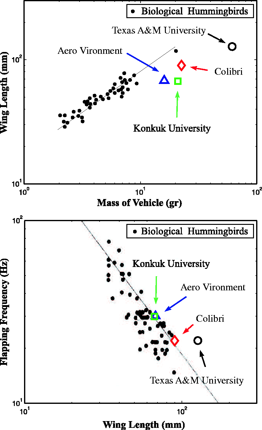
to quote only a few. Beyond the mere curiosity of mimicking nature, it is believed that the ornithopters will eventually outperform in agility the best quadcopters. Figure 1 compares the wing length versus mass and the flapping frequency versus wing length of hummingbirds
10
with their robotics counterparts; one observes that the flapping frequency versus wing length data of robotic ornithopters fit well those of the birds, while the wing length versus mass diagram indicates that for a given wing length, living hummingbirds have a mass nearly half of that of the robotic ones, which gives a clear indication that nature is still more efficient than technology. Note also that due to the complexity involved in mimicking all degrees of freedom of natural hummingbirds, the wings of the robotic system have a single degree of freedom which sweeps the wing in the stroke plane and the camber is achieved passively, leading to symmetrical trajectories for the upstroke and downstroke at hovering. On the contrary, living hummingbirds have additional degrees of freedom allowing the trajectory to deviate from the stroke plane (leading oval patterns and non-symmetrical contributions to the lift during upstroke and downstroke) and modify actively the camber.
Wing length versus mass and flapping frequency versus wing length of robotic and living hummingbirds (adapted from Greenewalt
10
).
The present project was started with no other ambition than explore the feasibility of the flapping flight; like most of the academic projects, it started with numerical models based on modified thin air foil theory, but it soon became clear that the project would be meaningless without the existence of a demonstrator; the construction of a prototype was started in 2012; the early stages of this project are described in Karásek.
11
Figure 2 illustrates the evolution of the net lift over the past four years (the numbers in the figure refer to different mechanisms, motor and wing designs which have been used). The net lift is the difference between the lift produced by the flapping wing at 21 Hz and the weight of the flapping mechanism in addition to the motor. In order to fly, the net lift force must exceed the weight of all the components necessary to operate the system (battery, attitude sensor, control board, attitude control actuators, etc.) plus the payload.
Evolution of the net lift at 21 Hz over the past four years The net lift is the difference between the lift produced by the flapping wing and the weight of the mechanism and motor that produces it.
System design
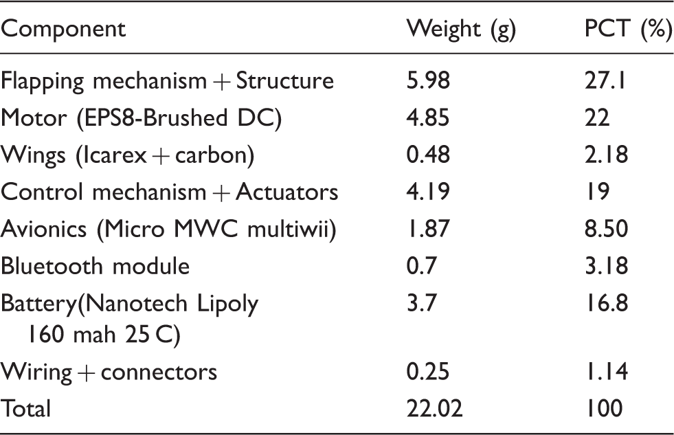
Figure 3 shows a general view of our vehicle which currently has a span of 21 cm and a weight of 22 g including battery and control electronics; the weight breakdown is given in Table 1. As a first step, the project has been focused on pitch and roll stabilization; there is no control on the yaw axis which is passively stable. The robot is currently in the early stages of flight tests; for a video, see the link provided in literature.
12
General view of the Colibri robot. Colibri weight breakdown.
Wing
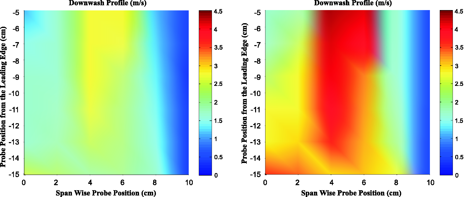
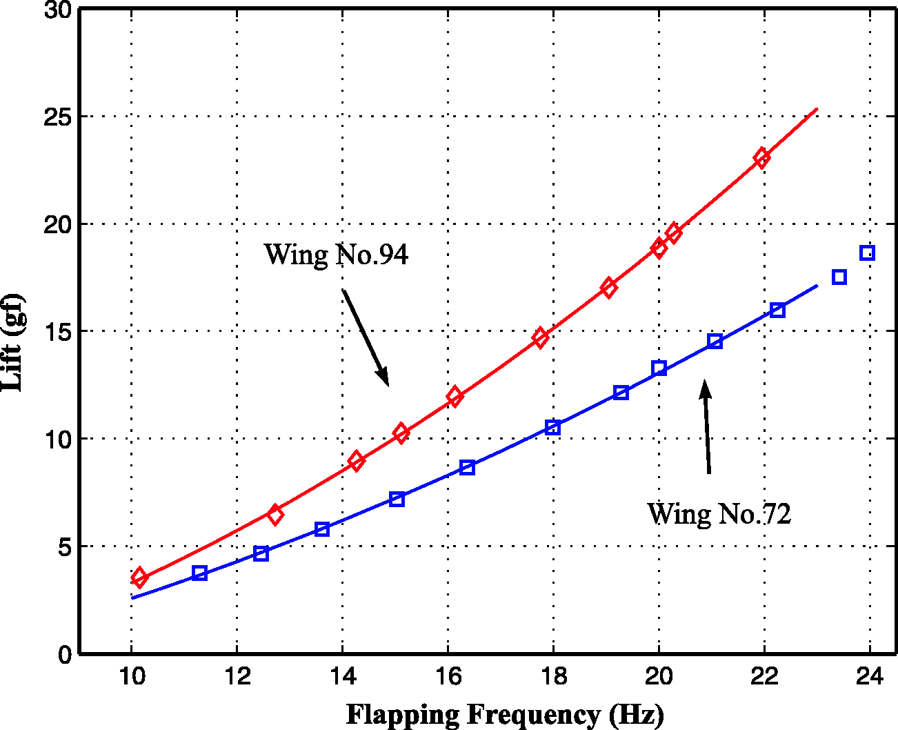
The wings have only a single degree of freedom (flapping) and the wing camber is obtained passively. They are made of a stiffened membrane and have two sleeves, one on the leading edge and the other one on the root edge. The sleeves accommodate the leading edge bar which is used for flapping and the root edge bar which is orthogonal to the leading edge bar in neutral position. The root edge bars are used for attitude control as we shall see in the Control mechanism section. The angle between the two sleeves when the wing is in flat configuration is called camber angle (β) as shown in Figure 4. Since this angle is greater than the angle between the bars in neutral position, the wing becomes cambered after the assembly (Figure 4). The wing camber is obtained passively as a result of the aerodynamic forces exerted on the wing during flapping, thanks to the camber angle β; in the current design, Three different wing shapes used in the project and camber angle β. Bottom left: current shape in flat configuration. Bottom right: Cambered wing after mounting in the leading edge and root edge bar. All configurations use Comparison of hot wire anemometer air flow measurements of the downwash air velocity profile in the plane below the robot. Left: wing no, 72. Right: wing no. 94. Lift versus frequency measurements with wing no. 72 and wing no. 94. The continuous line is best fit parabola.
Flapping mechanism
The mechanism for flapping the wing is shown in Figure 7. The motor input angle is θ and the output angle of the leading edge bar is φ. The kinematics is analyzed in detail in Karásek
11
(pp.126–127) and will not be repeated here. Figure 8 shows the output angle φ of the root of the leading edge bar as a function of the motor input angle θ; the theoretical curve (based on kinematics) is nearly harmonic, while the trajectories measured at 22 Hz deviate at the two extremes, because of inertia and backlash in the mechanism. Figure 9 shows an exploded view of the mechanism; all the parts are obtained by 3D printing; the technology applied is selective laser sintering (SLS); the material is Nylon PA2200 which satisfies the weight constrains and withstands easily high mechanical loads; the printing accuracy is around ±0.15 mm. The input of the mechanism is connected to the motor (EPS8-Brushed DC motor produced by AEO Company for radio controlled component) by a gear box with a gear ratio of G = 23.1:1. With respect to previous designs, the most remarkable differences are that (i) the gearbox is now placed on the same side as the motor with respect to the flapping frame, and (ii) a flanged bearing has been introduced between the gearbox and the mechanism. Figure 10 shows the characteristics of the motor (torque versus rotation speed) for various voltages and the (measured) torque requirements versus rotation speed (flapping frequency × gear ratio) of the flapping mechanism. In order to characterize the flapping mechanism load, the armature current and the flapping frequency are monitored and recorded for various motor voltages. Then the required torque is computed using the motor torque constant; a high speed camera is used to evaluate the flapping frequency. The crossing of the two curves is the operating point of the mechanism, provided that the corresponding current is below the thermal limit allowed for the motor.
Flapping mechanism consisting of a slider crank connected to a four-bar mechanism for motion amplification. The motor input angle is θ and the output angle of the leading edge bar is φ. Output angle φ of the wing root as a function of the input angle θ; the theoretical curve is based on kinematics; and the other curves are measured at 22 Hz. Exploded view of the mechanism. Torque versus rotation speed of the motor, for various voltages, and measured torque requirements of the flapping mechanism for a gear ratio of G = 23.1:1. The crossing of the two curves is the operating point of the mechanism.


Control mechanism
The pitch and roll torque moments are obtained by the so-called wing twist modulation which was pioneered in the Nano Hummingbird.
7
The flexible root edge bars are actuated as indicated in Figure 11 to modify the camber distribution along the span. A dissymmetry between the left and right wing will produce a roll moment, and a dissymmetry between the front and back half strokes will produce a pitch moment.
Wing twist modulation mechanism and its integration. Left: front view of the robot with the root edge bars bent to the maximum position to produce roll moment. Center: CAD view of the control mechanism. Right: side view of the robot with the root edge bars bent to the maximum position to produce a pitch moment.
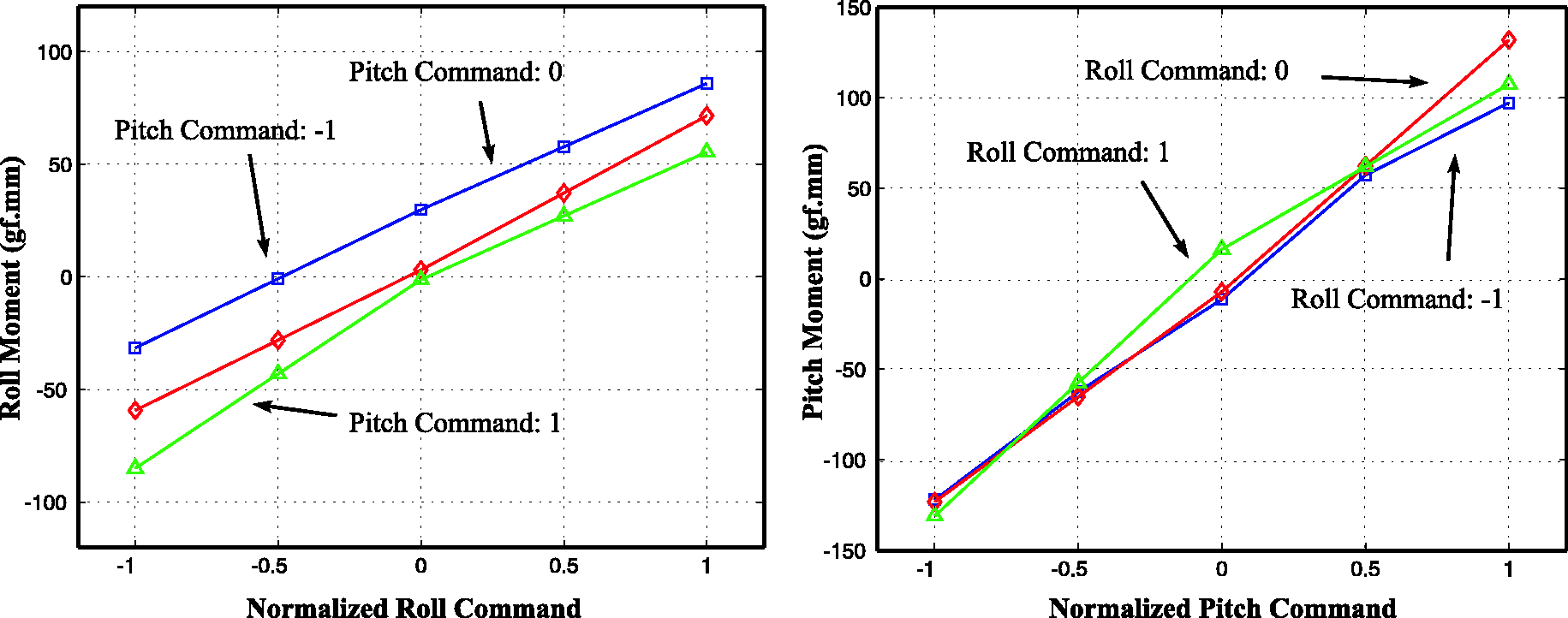
The bending of the root edge bars produces a reorganization of the air flow (Figure 12) which moves the center of pressure along the span without significantly affecting the global lift of the system, as illustrated in Figure 13. The left side of Figure 14 shows the evolution of the roll moment as a function of the position of the roll actuator (normalized to its maximum) for various positions of the pitch actuator; similarly, the right side shows the pitch moment as a function of the normalized position of the pitch actuator for various positions of the roll actuator. These curves have been found sufficiently decoupled to support independent control loops for pitch and roll.
Hot wire anemometer air flow measurements of the downwash air velocity profile in the plane below the robot when the roll actuator is at its maximum. Evolution of the lift for various positions of the roll and pitch actuators (normalized to the maximum). Pitch and roll moments for various positions of the control actuators.

Avionics
The flight control board selected is the Micro MWC Flight Control Board DSM2 ESC’s X4 Brushed integrated from HobbyKing; the main components of this control board are ATMEGA328P which serves as a processor, MPU 6050 Motion tracking device which combines a three-axis gyroscope and a three-axis accelerometer with an onboard digital motion processor (DMP) and a radio-receiver which is compatible with DSM2 Spectrum transmitter for acquiring pilot’s commands. In addition to the control board, the robot is equipped with a Bluetooth module SPBT2632C2A of ST Electronics as a wireless communication means in order to send all required data from the flight control to the computer. All the components are supplied with a single cell Nano-tech Lipoly Battery with the nominal voltage of 3.7, 160 mah capacity and the maximum discharge rate of 25 C. Due to the inherent features of the flapping wing mechanism, the accelerometer and gyroscope experience a harsh vibratory condition which affects their performance during flight. Among all possibilities tested, DMP algorithm with the sampling rate of 100 Hz integrated with a second-order Butterworth low pass filter and the cut-off frequency of 10 Hz showed satisfactory results in terms of the quality of the signals as well as phase shift. Another factor which affects the signal quality is how the board is integrated to the robot. Different experiments were performed with the robot attached to the gimbal system in order to evaluate the signal quality; the results revealed that the flapping frame is the best place for supporting the board in order to minimize the vibration noise. Various mechanical vibration isolation solutions involving elastomers were tested, but then abandoned. Figure 20 shows the quality of the signal obtained by the sensor when the robot is stabilized by a PD controller. The figure shows the roll and pitch measurements and the actuator command during a free flight test.
Modelling and control
Body dynamics model


Colibri parameters for the body dynamics model.


Coordinate systems and force diagram of forces for the longitudinal (pitch) equilibrium. (u is the longitudinal velocity along x-axis, q is the pitch rate, and θ stands for the pitch angle of the robot about the y-axis)
Colibri stability derivatives.

Actuator model
The dynamics of both linear and rotary actuators have been approximated by a first-order system and the time constant has been evaluated from their step responses; the movement of the actuators arm was captured by a high-speed camera. The results revealed that the rotary actuator (used for the roll axis) has a time constant T = 80 ms while the linear one (pitch axis) has a time constant T = 100 ms. Including the actuator, each axis may be represented by a state–space model with four states in which the last state is the actuator’s state (τa).
Control, stability, and sensitivity
Together with the actuator model, the block diagram of the pitch control system is that of Figure 16 (a similar one applies to the roll axis). The second-order Butterworth filter acts on the rate signal q with a corner frequency of 10 Hz. In order to stabilize the robot, a PD Controller is implemented: Block diagram of the closed-loop pitch dynamics including the actuator model.
If one disregards the low pass filter acting on the pitch rate, the closed-loop system equation is

Besides the control gains, the closed-loop poles depend on the position of the center of drag, zd (through the system parameters Pitch dynamics. Evolution of the closed-loop poles when the position of the center of drag zd with respect to the center of mass moves from −5 mm to +5 mm. Pitch dynamics. Evolution of the closed-loop poles for various values of the time constant T of the wing twist actuator (in msec).

Bias moment
Another important issue is the bias moments produced by the dissymmetry in the wing trajectory, resulting in the lift force not being exactly at the vertical of the center of mass, leading to pitch and roll moments (Figure 19). The problem was tackled by placing the robot in the gimbal system; the bias moments induced by the flapping wings will tilt the robot in the gimbal; the battery is moved in its support to modify slightly the position of the center of mass until the tilting is minimized. The residual bias moment Bias moment induced by the lift force not being at the vertical of the center of mass, leading to a bias moment Signals recorded during the flight tests, for roll and pitch. From top to bottom: angle, rate, normalized actuator command.


The moment of the resulting drag force will balance the bias moment. The feedback gain
Flight testing and simulation
A series of successful flights have been conducted using the set of control gains mentioned in the previous section. 12 Figure 20 is an example of signals recorded during the flight test. All data during the flight tests are transmitted to the computer by the Bluetooth module integrated in the robot. Although the results show the oscillatory behavior of the pitch and roll dynamics, the vehicle succeeded to cope with the inherent instability of the flapping wing dynamics.
In order to investigate the linear rigid body dynamics incorporated with actuators model presented above (equation (3)), computer simulations for the closed-loop system have been conducted; the control gains have the same values as for the flight tests and all stability derivatives are calculated based on the value of Simulation results for roll and pitch. From top to bottom: angle, rate, and normalized actuator command.
Summary and conclusion
The COLIBRI project has demonstrated hovering flight capability of a flapping twin-wing robot within the size of natural hummingbird. The first phase described in this paper led to a prototype with a total mass of 22 g, a wing span of 21 cm and a flapping frequency of 22 Hz; it is actively stabilized in pitch and roll by activating the root edge bars which changes the wing camber (mechanism known as wing twist modulation); this produces a reorganization of the airflow responsible for the roll and pitch control moments. The results showed that the roll and pitch axes are sufficiently decoupled to justify independent control loops. No control was considered for the yaw axis which is passively stable, and the vertical position was controlled manually by adjusting the flapping frequency. The robot flew successfully for the first time on 23 June 2016; the flight autonomy was 15–20 s (limited by the battery).
Future activities
Future activities will aim at:
Increasing of the net lift to allow the use of a bigger battery with a longer autonomy and other payloads; this may be achieved either by increasing the lift, or by decreasing the weight of the components. So far, no serious aerodynamic study of the airflow has been conducted besides the hot wire anemometer measurements reported above and the wing design has been done mostly on intuition and trial and error. We will seek collaboration of airflow specialists. Improving the flapping mechanism, with the double objective of reducing the vibrations induced during the flapping which induce noise in the control system, and increasing the flapping frequency, to increase the lift. A string mechanism is currently being tested. The implementation of the full state observer. The yaw axis is passively stable, but needs to be actively controlled to control trajectories.
Footnotes
Acknowledgements
The authors wish to thank the enthusiastic contribution of numerous foreign MSc students, and in particular Ignacio Senet Capote, Mylène Dumon and Carlos Santos.
Declaration of conflicting interests
The author(s) declared no potential conflicts of interest with respect to the research, authorship, and/or publication of this article.
Funding
The author(s) received no financial support for the research, authorship, and/or publication of this article.