
Abstract
Wing kinematics and wing deformation have a strong effect on the lift production and aerodynamic efficiency of bio-inspired flapping wing aerial vehicles. The goal of this study is to automatically track and classify wing kinematics components and wing deformation components of an insect-like flapping wing. Insight into wing motion and deformation characteristics may allow for improved performance of flapping wing drones. This work uses a stereoscopic high-speed camera setup and feature detection algorithm to measure the kinematics and deformation components of an insect-like flapping wing system with passive wing inclination. The wing membrane is painted with a black and white speckle pattern. Tracking and tracing of features on the wing surface is used to recover rigid wing kinematics and deformation of the entire wing surface throughout the wing stroke. Measurement results correspond with the characteristics of natural and artificial flapping wing systems in literature. The wing performs a figure-of-eight motion. The wing exhibits large deformations that vary throughout its stroke, related to both aerodynamic forces and inertial effects. Stroke velocity appears to influence angle of attack as well as spanwise bending, camber and twist.
Keywords
Introduction
Flapping wing fliers in nature, such as hummingbirds and insects, show impressive flight controllability at high aerodynamic efficiency.1–3 These promising aerodynamic characteristics have motivated researchers to develop artificial flapping wing micro and nano aerial vehicles (FWMAV and FWNAV).4–7 Several of these FWAVs are capable of lifting off the ground and performing controlled flight maneuvers. Flight times vary from a few seconds to several minutes.
Numerical simulations2,4,8,9 and experimental studies1,10–12 on (artificial) flapping insect wings indicate that both wing kinematics and wing deformation play an important role in aerodynamic force production and aerodynamic efficiency. Investigations into elastic flapping wing structures often study the effect of wing deformation by comparing force production and power consumption to a simulation of an identical rigid wing structure undergoing the same wing motion. The consensus is that spanwise bending, camber and twist have a beneficial effect on aerodynamic performance. Elastic wings outperform rigid wings in situations characterized by high angles of attack, such as insect-like flapping flight.1,9,13 The improved performance is attributed to a more stable attachment of the leading edge vortex (LEV), which prevents flow separation.4,9,14 Percin et al. 11 found that wing deformation is necessary for the wings to benefit from lift enhancing phenomena such as wake capture.
Several experiments have captured the wing motion and deformation of natural and artificial flapping wings. Camera experiments on natural fliers often involve manually tracking wing features frame by frame.15–17 This is a time consuming process, difficult for use in sensitivity studies.6,16 Other studies draw markers, usually a few dozen,6,10 onto the wing surface and track them either manually or by (semi-)automatic computer tracking algorithms. 18
This study applies a speckle pattern to the wing surface and tracks wing features through feature detection. Use of a stereoscopic camera setup allows for a three dimensional reconstruction of wing kinematics and deformation. Visualizing the wing kinematics and wing deformation may inform improvements in driveline design and wing design. Improved design may result in higher lift capacity, increased flight endurance and flight control.
Materials and methods
This work uses an experimental investigation of wing kinematics and wing deformation on an artificial insect-like flapping wing. Figure 1 shows the artificial wing. The wing membrane is a

The wing has a skeleton with four carbon fiber rods attached at the wing base. Two outer rods form the wing leading edge (LE) and root edge (RE). Two inner rods (R1 and R2) add stiffness to the wing. A Mylar sheet covers the carbon fibre skeleton and forms the wing membrane. L is the length of the wing membrane, measured along the leading edge. The chord length c is defined as the distance from the leading edge to the trailing edge (TE), measured perpendicular to the leading edge.

Experimental setup (left), with close-up of driveline and speckle pattern wing (right).
Wing parameters.

Experimental setup
Figure 2 shows the experimental setup. The setup uses two cameras (Ximea xiB-64 BC120RGCM-X8G3 and JAI SP-12000M-CXP4) that capture wing motion. The transparent wing membrane is covered with a layer of white spray paint and a black speckle pattern of approximately 800 dots with a diameter of approximately 1 mm. Speckle patterns have been used in the past to determine insect-like flapping wing characteristics. Wu et al. 18 used a speckle pattern flapping wing in vacuum to distinguish between inertial and aerodynamic contributions to wing deformation. Doan et al. 19 used a speckle pattern wing to perform modal analysis on an insect-like wing structure. The effect of spray paint on wing inertia and wing structural properties is negligible. The painting process increases wing mass by 0.012 grams or approximately 5%.
Motion tracking
The camera image acquisition is synchronized by a trigger unit. Frame rate is set to 800 Hz. At a stroke frequency of 20Hz, 40 images are taken per stroke cycle or 20 images per stroke. Exposure time is set to 100

(a) Illustration of wing kinematic parameters. Wing kinematics consist of three rotations, expressed with respect to a fixed coordinate system
Wing kinematics
Rigid wing motion requires three angular parameters: stroke
Determining stroke, deviation and inclination from tracked point data is relatively straightforward. The wing rotates around its leading edge, so points 
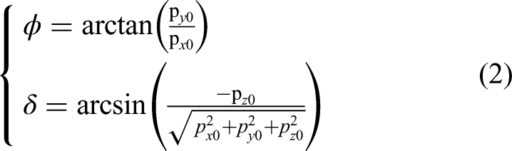
To determine inclination, a rigid wing plane is fitted through the marker coordinate data. The rigid wing plane corresponds to the
Wing deformation
Three components together describe wing deformation: spanwise bending, camber (chordwise bending) and twist (torsion). Figure 3b illustrates each deformation component.
The wing membrane is divided into wing chords. Chords are thin strips of wing membrane oriented perpendicular from the LE to the TE, as shown in Figure 3b. Tracked points are assigned to wing chords based on their distance from the CoR, measured along the LE. For each chord, the LE and TE are computed based on the average of a subset of the three highest and three lowest detected points within that chord.
Spanwise bending
Camber
Twist
Per wing chord there is a single value for spanwise bending, a single value for twist and camber varies along the chord.
Results
Kinematics measurements
Figures 4 and 5 show the measured wing kinematics. Figure 4 shows the evolution of the deviation angle and the inclination angle throughout wing stroke. Figure 5 shows the wing tip path. The wing motion has a stroke amplitude of 120°. The deviation angle ranges from At the start of wing stroke, the wing has a high angle of attack and moves downward. The high angle of attack is approximately constant until midstroke ( As the wing approaches midstroke, the wing moves upward. After midstroke the wing pitches down, so the angle of attack decreases. The decrease in angle of attack is likely due to stronger aerodynamic forces acting on the wing membrane, caused by high stroke velocity. Near the end of stroke, the wing stroke velocity decreases. The wing pitches back towards zero inclination angle. The wing also moves back to its deviation angle from the beginning of stroke.

Evolution of (a) deviation angle and (b) inclination angle throughout stroke. The wing moves from left to right.

Bold dots show the wing tip path, moving from left to right. The data points are mirrored (transparent dots) with respect to
Figure 6 shows a side view of the wing motion from start of stroke (
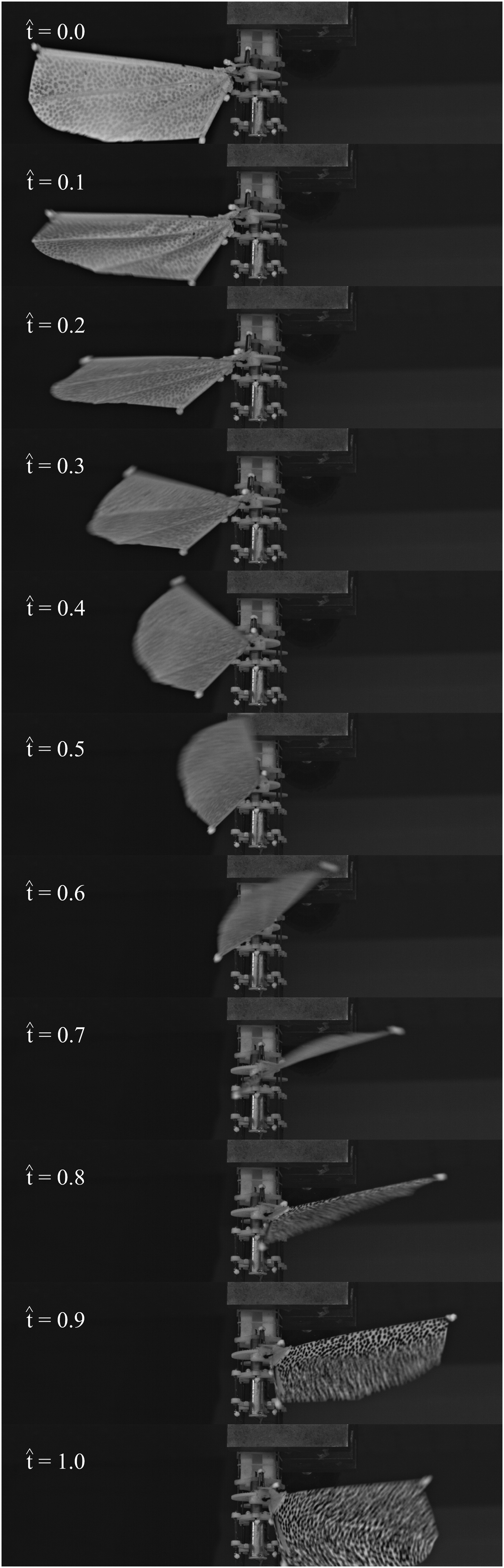
Side view of wing motion.
Deformation measurements
Figure 7 shows the evolution of each wing deformation component throughout wing stroke.
At the start of stroke ( Towards midstroke ( Deformation after midstroke ( As the wing nears the end of stroke ( At the very end of stroke (

Evolution of deformation components throughout stroke: (a) Nondimensional spanwise bending; (b) Nondimensional camber; (c) Twist, in chronological order from top to bottom.
Discussion
The measured wing kinematics follow a logical evolution that agrees with findings from literature.6,7,16 Roshanbin et al. 6 measured a similar wing tip trajectory for their flapping wing mechanism, where the wing initially appears to strongly deviate down, then comes back up toward midstroke and returns to its mean value near end of stroke. Maeda et al. 16 measured the same motion profile on a hummingbird in hovering flight. Previous in-house measurements by Timmermans 7 show a double figure-of-eight pattern when using the same driveline mechanism at a lower stroke amplitude. The wing exhibits a large initial oscillation followed by a second oscillation at lower amplitude, creating a double figure-of-eight pattern. Aerodynamic forces acting on the wing membrane may explain this change in deviation motion profile. At higher stroke velocity, the increase in aerodynamic force acting on the wing membrane prevents the wing from deviating downward a second time.
Wu et al. 18 measured total structural deformation of an artificial flapping wing reinforced with internal veins, which is closest to the wing design that is used in this study. Although they did not separate deformation contributions into spanwise bending, camber and twist, a comparison can still be made. The wing deformation in this work follows a very similar evolution to that measured by Wu et al. Along the leading edge, the out-of-plane deformation increases gradually on the part of the wing that is closest to the wing root and then increases more rapidly towards the wing tip. As stroke velocity increases, deformation related to camber and twist is highest at the trailing edge near the wing tip, where the structural stiffness is lowest. Wu et al. measured a total deformation of 18% compared to chord length. The overshoot related to inertial effects at the end of stroke also agrees with the findings of Wu et al. Camber values between 10% and 25% of mean chord length are common in elastic insect-like flapping wing systems.13,16,17,21 Camber increases along the wing span. A maximum in positive camber is observed near midstroke. All these observations in literature agree with the findings from the previous section. Hummingbirds and artificial flapping wing systems without internal venation experience higher twist values, with maxima up to 60°.10,15,16
The measurements from the previous section successfully characterize individual wing kinematic components and deformation components. Measurement values and profiles correspond to findings from literature. The experimental setup and processing methodology are suited for additional investigations into wing kinematics and deformation. Future research efforts should explore the effects of wing actuation parameters such as stroke amplitude and stroke frequency and wing design parameters such as vein diameter and venation pattern on wing deformation and aerodynamic performance. Also, the wing structural resonance frequency should be considered during the wing design process, as flapping wings appear more efficient when actuated close to their structural resonance frequency.4,8 Insights from such extensive investigations should prove useful for the wing design process and lead to improved lift production and power requirements of FWAVs. Experiments should be performed under hovering conditions as well as conditions that mimic forward flight, in order to reveal the effects of an additional incoming airflow on wing kinematics and wing deformation. Elastic wing models offer opportunities in the construction of flight controllers that account for the effects of wing deformation. Such models may be especially useful to FWAVs with passive inclination motion, as changes in driving parameters such as stroke amplitude influence or maneuvers such as forward flight also affect the inclination motion. This can affect aerodynamic force production in a non-obvious way. 3 The influence of a control action or flight maneuver on force production is therefore especially difficult to predict in FWAVs with passive wing motion.
Conclusion
This work uses a stereoscopic high-speed camera setup to track wing motion and deformation of an artificial insect-like flapping wing mechanism. The wing tip undergoes a periodic figure-of-eight motion. Wing inclination is largest after midstroke, when stroke velocity is highest. The wing exhibits large deformation throughout the stroke. When stroke velocity is high, aerodynamic forces likely dominate the wing deformation. At and around stroke reversal, inertial effects are more prominent. Both the kinematics and deformation correspond well with findings from literature.
The large deformations are expected to have a strong effect on aerodynamic force production and aerodynamic efficiency. Follow-up experiments should be performed that include measurements of lift and power consumption. A sensitivity analysis may be performed into the effect of actuation and wing design on wing kinematics and wing deformation and linked with lift production and power consumption. Insights gathered during additional experimental campaigns may lead to improved wing designs with better aerodynamic performance and to a low-computational cost aerodynamic force production model that accounts for wing deformation.
Footnotes
Acknowledgments
The control circuit that drives wing stroke motion was designed by Tom Henskens, KU Leuven, Celestijnenlaan 300 box 2420, Leuven, Belgium.
Funding
The author(s) received no financial support for the research, authorship and/or publication of this article: The Research Foundation - Flanders (FWO) is gratefully acknowledged for its support through research grant numbers G095120N and 1S60222N. Internal Funds KU Leuven are gratefully acknowledged for their support.
Conflicting interests
The author(s) declare that there are no potential conflicts of interest with respect to the research, authorship, and/or publication of this article.