
Abstract
Maneuverability of flapping wing fliers inevitably goes with inherent system instability. Inherent instability means that flapping wing systems require a flight controller and that these vehicles are prone to crashing. This work proposes a design feature to stabilize the descent of a flapping wing aerial vehicle. The vehicle is based on the KUlibrie, a flapping wing nano robot that is under development at KU Leuven. A computational study indicates that upwardly elevated wings provide inherently stable descending flight. The vehicle performs a free flight starting from different initial conditions. The system dynamics display convergence towards a limit cycle. Wing elevation and center of gravity position determine pitch and roll stiffness with respect to vertical descent and climb. The same effects that stabilize descent also destabilize climbing flight.
Introduction
For a long time the impressive flight capabilities of insects and hummingbirds have captured the attention of researchers. These natural fliers exhibit a high degree of maneuverability and flight control, which makes them well suited for navigating confined environments. Much effort has been invested in understanding and modeling the aerodynamics of flapping flight2,1,3,4 and in the development of aerial robots that mimic the flapping wing mechanism for lift production.5–10 While conventional fixed wing and rotary wing drones are well suited for applications in large open areas, 11 insect-like flapping wing micro air vehicles and nano air vehicles (FWMAVs and FWNAVs) can be deployed in confined spaces that are difficult to navigate for other types of aerial vehicles. 12 Compared to fixed wing and rotary wing vehicles, flapping wing drone performance characteristics make them an attractive technology for applications that require downscaling.11,13 Examples of applications where insect-like flapping wing drones may be deployed are in greenhouses for monitoring crop health, navigation inside collapsed buildings after a natural disaster, and the inspection of difficult to reach parts of industrial installations. 11
Significant progress has been made in the development of insect-like flapping wing aerial robots. Several prototypes from different research groups are capable of untethered hovering flight. Some of these prototypes are capable of carrying a small payload14,5 and can reach flight speeds of several m/s.14,15,5 The DelFly Nimble is even capable of challenging flight maneuvers such as banked turns. 15
An important challenge in the development of flapping wing aerial vehicles comes from the inherent instability of these vehicles. It is their inherently unstable flight characteristics that give natural fliers the capacity for highly agile flight maneuvering. 16 However, for flapping wing robots the inherent instability places a high demand on the flight controller.15,10,17 The flight controller continuously needs to apply small control actions to ensure that the vehicle does not diverge from the desired position or desired attitude. If the flight controller fails, the vehicle is at risk of toppling over and crashing.
Previous research has investigated the effect of adding sail-like structures onto flapping wing aerial vehicles. 18 While these structures increase passive vehicle stability, they also add weight to the system. Furthermore, the added aerodynamic damping that results from these structures decreases vehicle agility. Some prototypes employ wing buckling mechanisms 19 and soft molds with internal skeletons 20 to increase robustness against collision disturbances, however flight control and general disturbance recovery remain important challenges. Observations of natural fliers indicate that insects control their flight by altering the passive characteristics of their wing force production and by exploiting stabilizing phenomena.15,22,21,23
This work considers a novel design feature for flapping wing aerial vehicles that maintains vehicle agility in maneuvering flight and that at the same time stabilizes descent. Flapping wing aerial vehicles traditionally move their wings in a body horizontal plane.5–10 This work considers a design feature where the wings are mounted in an upward elevation angle. Upward wing elevation creates a stabilizing effect similar to the lateral stabilization that results from an airplane wing dihedral.24,25 For flapping wing aerial vehicles this stabilizing effect is present both along the body lateral axis and along the body longitudinal axis. Simulation results indicate that the effect of upward wing elevation is strong enough to stabilize descent, while hovering conditions and climbing flight remain inherently unstable. The vehicle is guaranteed of flight recovery, while it theoretically remains capable of agile flight maneuvering.
The unstable flight characteristics of flapping wing aerial vehicles pose a challenge for experimental analysis. Without a flight controller the system immediately diverges. For systems with a flight controller it is only possible to observe the characteristics of the controlled system, because the observation of the system stability characteristics is influenced by control actions from the flight controller. Some studies use live insects to observe flight characteristics.23,26,22 These measurements are influenced by the control actions of the insect. Many studies rely on simulation data instead.17,7,27,16,21 This work performs a computational study on the effects of wing elevation on the stability characteristics of an FWMAV.
The paper begins with a description of the FWMAV under consideration. The inertia and wing characteristics are described, as well as the wing kinematics. Next is a description of a quasi-steady force production model and of the free flight simulation procedure. The force production model and the flight simulation are used to analyze the vehicle flight pattern and stability characteristics. Special attention is paid to the influence of wing elevation on aerodynamic forces and torques that occur in dynamic flight. The analysis of these forces and torques explains why wing elevation stabilizes descent, while other flight conditions remain inherently unstable.
FWMAV model and methodology
The reference model is a tailless two-winged flapping wing micro air vehicle that is under development at KU Leuven, named KUlibrie.28,13 Table 1 gives an overview of the mass, wing dimensions and moments of inertia of a novel prototype that is in preparation for flight testing. The system mass, inertia and wing design characteristics are comparable to those of similar sized FWMAVs3,7. Figure 5 illustrates the wing root-to-tip length
Body inertia and wing characteristics.

Flapping wing kinematics
The complex wing motion of insect-like fliers is approximated by three rotation components: stroke
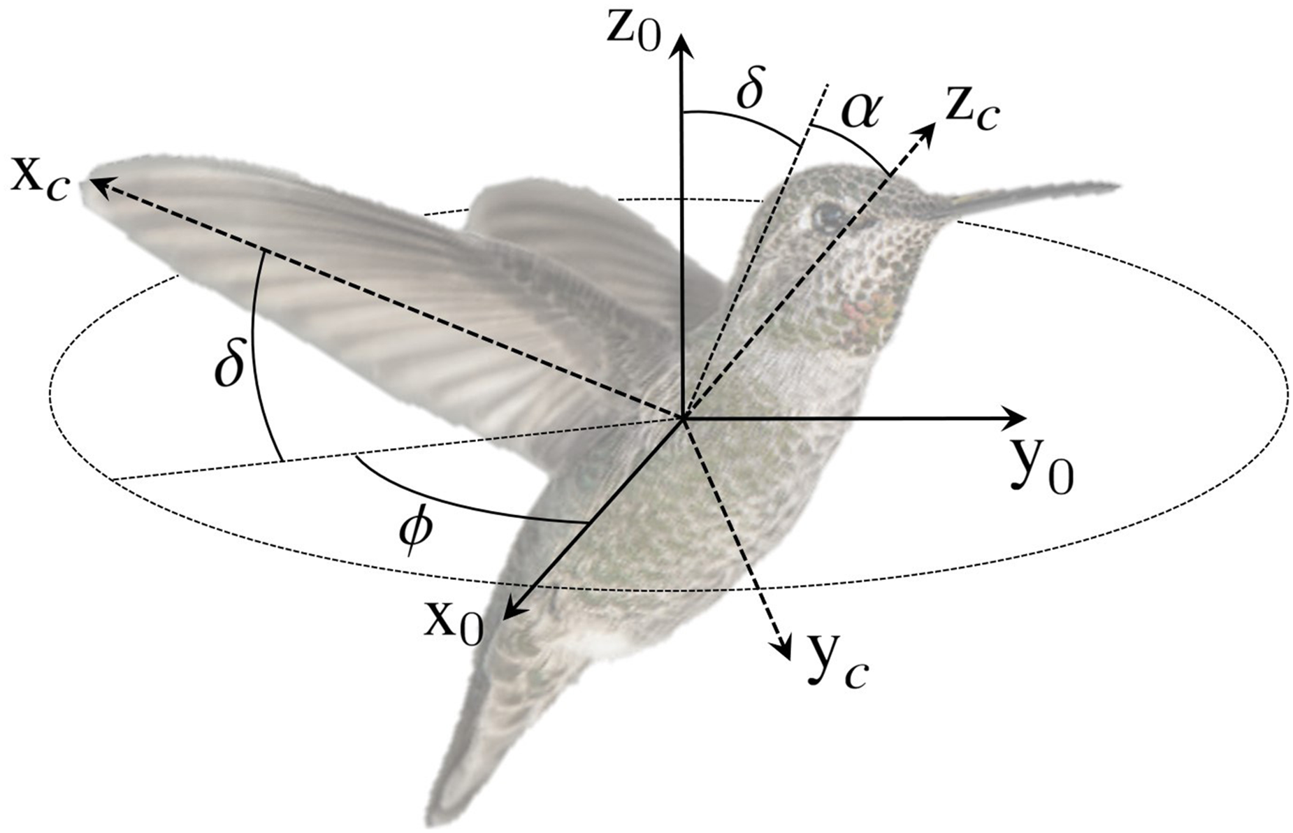
Three rotations describe the wing motion: stroke
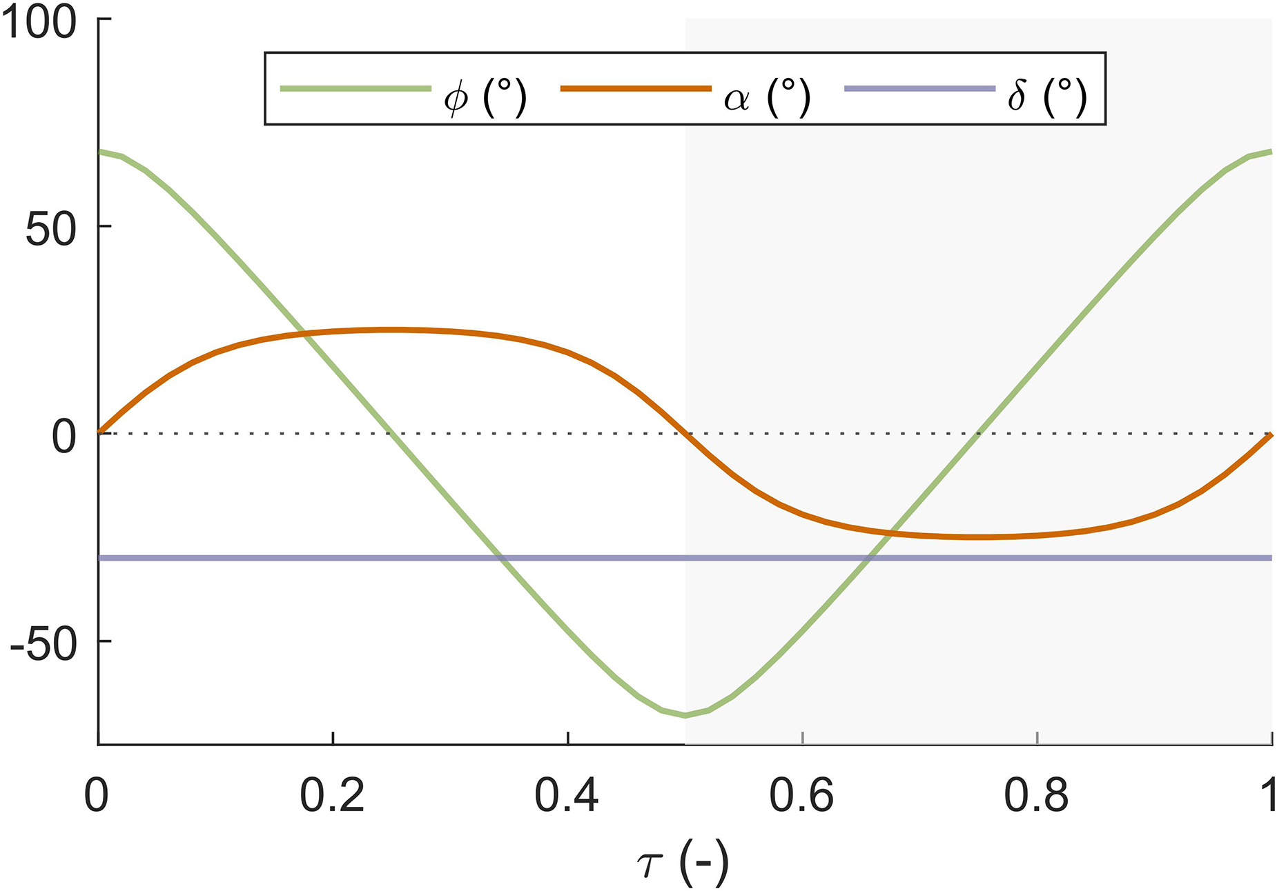
Wing motion consists of three rotations. A stroke cycle consists of an upstroke (white area) and downstroke (gray area). During wing stroke the inclination angle remains nearly constant. At the end of each stroke the wings rotate around the leading edge to establish a positive angle of attack at the start of the next stroke.
Wing stroke is the periodic rotation around the 

Influence of shape factors
Wing elevation is the wing motion out of the body horizontal plane and around the rotated

Wing leading edge path for no wing elevation (left) and for upward wing elevation (right). The wings move from the front of the body to the back of the body during upstroke. During downstroke the wings move from the back of the body to the front of the body. Without wing elevation, the leading edge moves in the body horizontal plane. Application of a mean elevation angle
Wing inclination is the main determining factor of the angle of attack. The inclination motion is the periodic rotation of the wing around its spanwise axis
29
:

Force production model
A quasi-steady modeling approach is used to compute aerodynamic force production. This approach assumes that aerodynamic force production can be expressed as a function of the instantaneous wing kinematics only.4,3,31 Quasi-steady modeling and computational fluid dynamics (CFD) are the two most common approaches in flapping wing force modeling. 3 The choice whether to use the quasi-steady approach or CFD depends on the application. Quasi-steady models usually employ simple analytic functions to compute force production from wing motion. The result is a low computational cost, at the risk of neglecting some aerodynamic phenomena.3,32 CFD models solve the Navier-Stokes equations in order to compute aerodynamic force production from the induced air velocity field. The CFD approach provides useful insights into aerodynamic phenomena related to flapping wing flight,32,21,3 but model validation is demanding and the computational cost is high. This is why CFD is mostly used to study specific aerodynamic phenomena32,21 or as a baseline for the accuracy of quasi-steady models.33,7 Quasi-steady models are well suited for comparison of different designs and operating conditions.3,33 This work studies the effects of a design adaptation. The flight behavior is analyzed for multiple wing elevation settings and for variable initial conditions. Because of the high number of simulations, this works employs the quasi-steady modeling approach. The wings are approximated as rigid surfaces. In practice, even stiffened wings exhibit a clear wing deformation.13,34 The rigid wing assumption is made to limit the model complexity and also because of the limited availability of experimental data that is necessary to evaluate a flexible wing model.13,34 The effect of wing flexibility may be non-negligible but the present simplification to a rigid wing does not invalidate the analysis of flight stability. The expansion of the model to include wing flexibility is left as a subject of future research.
Aerodynamic force production is calculated based on blade element theory. The wing is considered as a series of infinitesimally thin chords. In this study, chord width is set to 0.1 mm. A finer chord mesh does not significantly alter the simulation results. The total aerodynamic force 


By adding moment arms to the description of equations (3 to 6) the computation of aerodynamic torque is relatively straightforward. This model was derived by Wang et al.
31
for flapping wings under hovering conditions. The model of Wang et al. does not rely on empirical data. The general descriptions for the individual force components make the model applicable to a wide range of designs and operating conditions. The formulas presented here are for the specific case of an inclination motion around the leading edge. Comparison of quasi-steady models with CFD models shows that quasi-steady models that take wing rotation and wing-wake interaction into account are adequate for stability analysis of flapping wing fliers.
33
The quasi-steady model presented here takes these contributions into account. In-house experiments have confirmed the accuracy and reliability of this aerodynamic model for hovering conditions.
36
For free flight, the absolute velocity of a local wing chord is the sum of the velocity related to body motion and the relative wing motion of the wing with respect to the body:


The aerodynamic force production model used in this work is adapted for dynamic flight conditions. At small velocities, the model is expected to agree well with reality. Whether the model remains accurate at higher flight speeds of several m/s, is left for future experimental investigation.
System dynamics
The previous section describes the computation of instantaneous aerodynamic force components and torque components based on the instantaneous total wing velocity. The equations of motion in equation (11) give the vehicle body acceleration 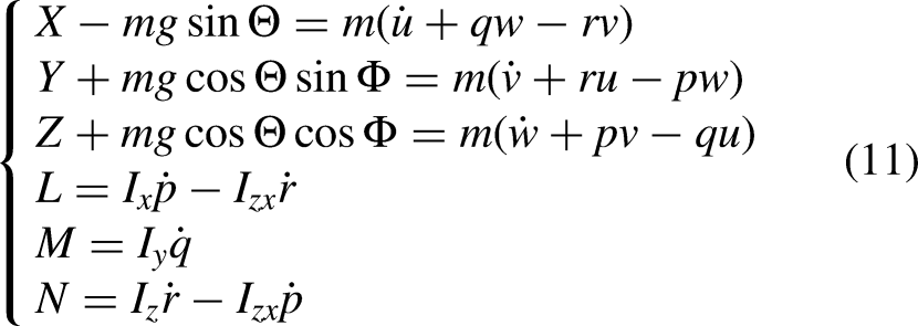
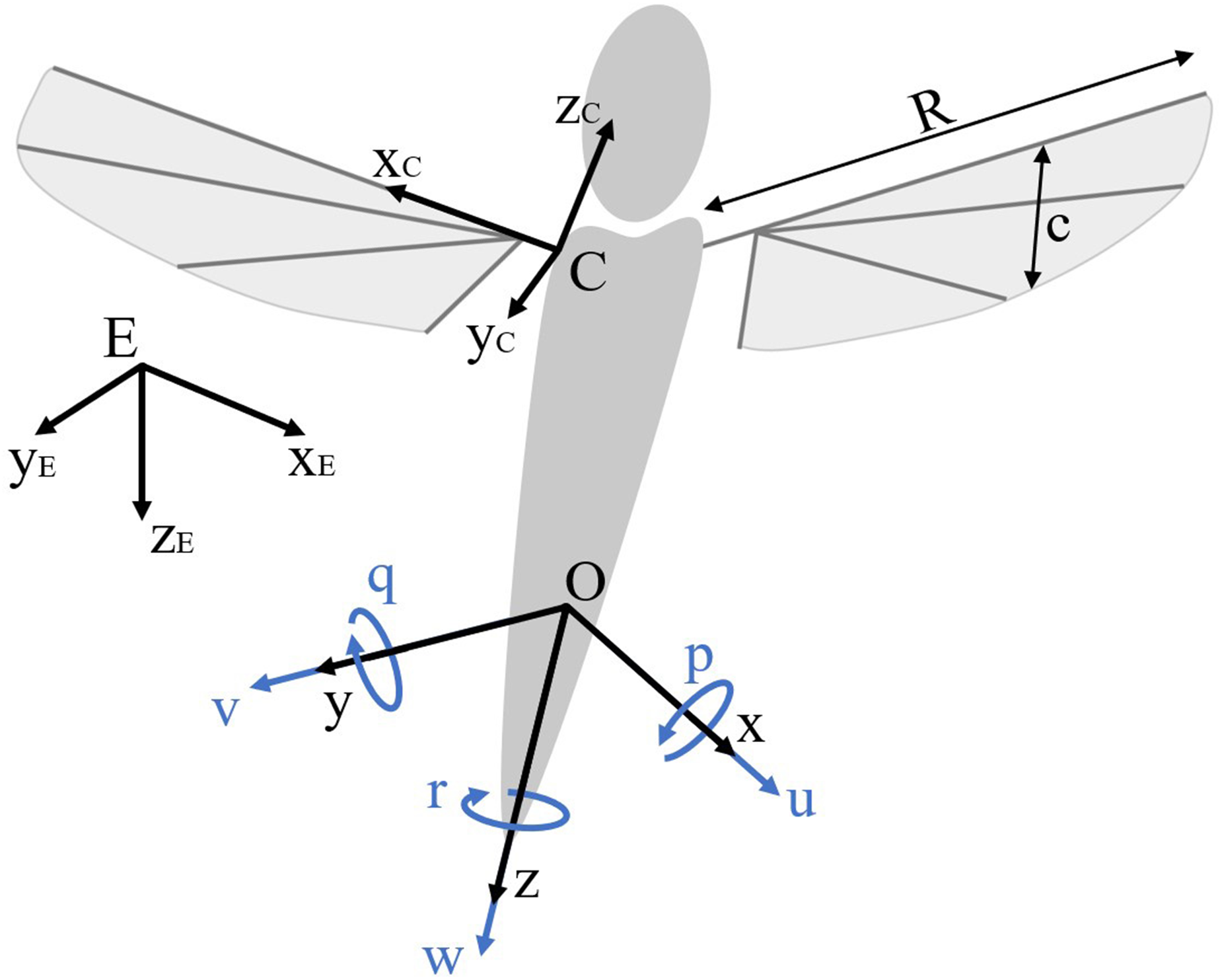
Model flier showing body motion, wing positioning and wing geometry. The motion components
The relation between the vehicle rotational velocity and the vehicle attitude is given by Etkin B and Reid,
24
Karásek M and Preumont
33
:

Simulation procedure
Figure 6 gives an overview of the flight simulation procedure. In free flight, the body has six degrees of freedom:

Schematic overview of the free flight simulation procedure.
Several studies on flapping wing flier stability use direct averaging of the forces during the stroke cycle.26,38,16,39–41 Direct averaging simplifies the calculation of mean force production and reduces the computational cost of the simulation. Taha et al. 23 have shown that direct averaging may lead to incorrect conclusions on stability characteristics, because this technique neglects the fast body dynamics. The term fast body dynamics refers to the motion of the system within one flapping cycle.23,21,27 This work does not use direct averaging. Because force production and body acceleration are computed at each time step in the flapping cycle, fast body dynamics are taken into account.
Results and discussion
The simulation procedure is used to investigate vehicle dynamics in different flight conditions. This section begins with the results of a free flight simulation starting from hover. The dynamic behavior of the vehicle is then studied for simulations starting from different initial flight conditions. Next, the influence of wing elevation on force and torque production is studied for different flight conditions. The analysis of the effect of this adaptation on force and torque production explains the dynamic behavior of the system.
Free flight characteristics
The vehicle is released from standstill in an upright position. At standstill the vehicle produces a mean lift force of 12 cN (approximately 12 gram force), which is lower than the vehicle self weight. The vehicle goes into a descent. Figure 7 shows the longitudinal system dynamics. The plots on the left are used in the analysis of the evolution of the longitudinal motion:
The initial hovering state is an inherently unstable flight condition.41,39,40,7 The system deviates from the upright position. A longitudinal oscillation forms with a large forward velocity amplitude and large pitching amplitude. The mean lift force is lower than the vehicle weight, so the vehicle starts to descend. The large pitching amplitude causes the lift vector to deviate away from the global z-axis. The vehicle only produces a small lift force, so it reaches a high descent rate. The high descent rate increases the magnitude of restoring forces and torques acting on the vehicle. The vehicle forward velocity oscillation and the pitching oscillation decrease in amplitude. The vehicle attitude is closer to upright. The orientation of the lift vector is closer to the global z-axis. Also, the high rate of descent results in increased lift production. The vehicle rate of descent decreases. The system converges to a state where mean lift force is equal to the vehicle weight. Longitudinal oscillations have a constant amplitude.

Longitudinal body dynamics over a twenty second time period (left) show that after an upright release from standstill, the system converges to a stable oscillatory condition. A state space representation of the longitudinal motion components after convergence (right) shows the formation of limit tori. The vehicle oscillates (fast body dynamics) around a limit cycle (slow body dynamics). The instantaneous values are represented with light fine lines. The bold dark lines show the slow body dynamics.
A state space representation on the right of Figure 7 shows the longitudinal vehicle oscillations after convergence. This representation shows the formation of limit tori. The vehicle dynamics can be categorized into slow body dynamics and fast body dynamics. The slow body dynamics represent the mean vehicle motion over the course of a stroke cycle. Slow body dynamics show up as a limit cycle. The slow body motion is a pitching oscillation at frequency 1.84 Hz with an amplitude of 20
Figure 8 shows the lateral system dynamics. The vehicle starts from a 2
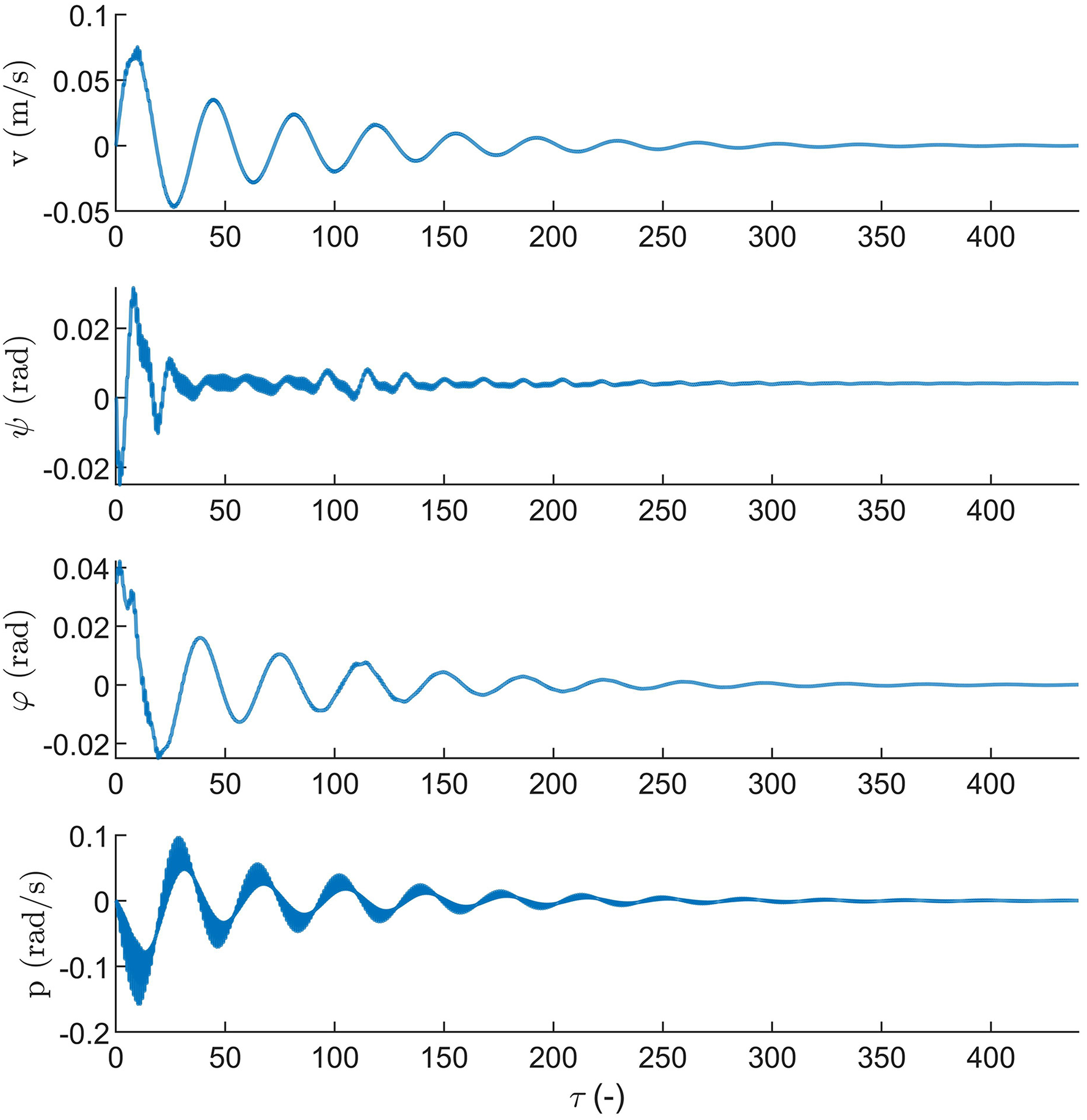
Lateral body dynamics over a twenty second period. The system starts from an initial roll angle disturbance
Figure 9 shows flight paths for three different initial conditions. The flight paths are displayed (a) starting from hover, (b) a translation to the right, (c) from a forward translation and (d) released from an upside down attitude. The behavior after starting from hover was already analyzed earlier in this section. For the other initial flight conditions, the vehicle initially tilts away from the incoming airflow. This slows down the vehicle. In each case the flier goes into a descent and converges to the same flight pattern. The stable flight condition is the superposition of a constant rate of descent and an oscillatory pitching motion around the upright orientation. The stable rate of descent is 42 cm/s. The flier descends over several meters before reaching its limit condition, however Figure 9 shows the vehicle performs an upright vertical descent much earlier.

Flight paths beginning from a) hovering conditions, b) translating to the right at 2 m/s and tilted over a
Impact of wing elevation on force and torque production
To study the effect of wing elevation on force and torque production under different flight conditions, the simulation procedure is slightly adapted. The vehicle velocity and attitude are kept constant. In Figure 6, this corresponds to skipping over the computation of the acceleration according to the equations of motion so that acceleration is zero. In literature, the method of analyzing force and torque components under different flight conditions is commonly used to determine the stability characteristics of flapping wing fliers.7,33,38,32,39–41
Force and torque production in response to body horizontal translation
Cycle averaged force and torque are compared for increasing settings of wing elevation. Stroke and inclination motions are kept unchanged. The elevated wings are scaled to produce equal average lift at hover. The scaling procedure is performed by iteratively scaling the wing until average lift production at hover is equal within an accuracy of 0.001 N. For the largest considered wing elevation setting of Force and torque both increase with wing elevation. The effect of wing elevation on forces is small at low wing elevation angles and increases more significantly at large elevation settings. The most notable impact of wing elevation is on the torques. At small elevation settings the torque increases approximately linearly with wing elevation. At an elevation setting of

Cycle averaged counter force (solid lines) and counter torque (dashed lines) in reaction to a) longitudinal velocity
Figure 4 shows why wing elevation increases the counteracting forces and counteracting torques in response to longitudinal and lateral translation. The airflow relative to the wings changes in the case of wing elevation. In case of no wing elevation, when the wing leading edge is aligned with the incoming airflow the wing is parallel to the airflow. There is then zero drag resulting from the body motion. In the case of wing elevation, for the same stroke angle the wing is no longer parallel to the incoming airflow. The airflow has a component perpendicular to the wing surface. This component creates a force and torque, pushing and tilting the system away from the incoming airflow. The first wing that encounters the incoming airflow experiences a relative upward airflow pushing the wing up. The second wing experiences a relative downward airflow pushing the wing down. The vehicle experiences a net torque that tilts the system away from the incoming airflow. Also, wing elevation raises the position of the wing center of pressure compared to the system center of gravity. The force lever is longer, further increasing the amplitude of aerodynamic counter torques. The increase of longitudinal and lateral counter force and counter torque in response to motion implies that wing elevation increases the vehicle disturbance rejection with respect to hover.
Restoring torque in response to descent
Figure 11 shows the effect of wing elevation and COG position on torque induced during vertical descent, while the vehicle is tilted forward or to the right. The torque amplitude increases linearly with the rate of descent. This result agrees with observations in literature.33,7,16

Influence of wing elevation on aerodynamic torque production during vertical climb / descent. a) Mean aerodynamic pitching torque. The drone is tilted forward by 30
Wing elevation and COG position impact the net aerodynamic torque production:
The induced torques are significantly larger for the elevated wings setting. For descent, a net aerodynamic torque is created that tilts the vehicle away from the incoming airflow and toward the upright position. In the case of no wing elevation and with the COG positioned below the wings center of pressure, there is still a net torque in response to the vehicle translation. The net torque is smaller than in the case with elevated wings. In case there is no wing elevation and the COG is positioned at the same height as the wing center of pressure, the aerodynamic torque production is zero.
When the center of gravity is at the same height as the center of pressure, the aerodynamic torque in response to motion disappears. This is because there is no moment arm, so only aerodynamic forces are produced.
When the COG is moved down with respect to the wings, a moment arm builds up between the wing center of pressure and the vehicle center of gravity. Aerodynamic counter forces in response to body motion create a net torque that tilts the vehicle away from the incoming airflow. This effect introduces a pitch and roll stiffness that stabilize descent.
In the case of wing elevation, the increase in aerodynamic torque in response to body motion can be explained in a similar manner. Wing elevation shifts the center of pressure upward with respect to the center of gravity, which creates a longer moment arm. Also, when the system is tilted, one wing encounters the airflow at a steeper angle. The result is a high drag force. The other wing encounters the airflow at a more shallow angle, which results in a lower drag force. The combined effect is a net force moment. This effect is not present without wing elevation. In case of no wing elevation, both wings encounter the airflow at the same angle. Then there is no additional force moment.
Destabilized climbing maneuver
The results in Figure 11 also indicate that while the effects of wing elevation stabilize the descent by increasing the restoring torques, the same effects further destabilize climbing flight. For climbing flight, again the torques in response to vehicle translation increase. However, the sign of the aerodynamic torques is opposite compared to descent. When a tilted vehicle with elevated wings performs a climb, again one wing encounters the incoming airflow at a steeper angle. The other wing encounters the airflow at a shallower angle. The result is a net torque that tilts the vehicle away from the incoming airflow and away from the upright position.
Aerodynamic efficiency
Wing elevation may have an effect on the aerodynamic efficiency of the system. To investigate the impact of upward wing elevation on aerodynamic efficiency, the lift-to-power ratio of the flapping wing system is calculated at different elevation settings. The lift-to-power ratio expresses how efficiently the wing system converts inputted energy into lift. At hovering conditions, the power that is used to move a wing chord through the air is the scalar product of the wing chord velocity and the aerodynamic force acting on that wing chord: At small elevation angles, the impact on lift-to-power ratio is minor. A wing elevation angle of 15 At larger elevation angles the impact on lift-to-power ratio is more significant. At an elevation angle 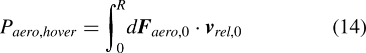

Influence of wing elevation on lift-to-power ratio, for equal wing shape, stroke and inclination motion.. Wing size is adjusted so that lift production is equal.
Flapping wing kinematic parameters.

Study limitations
The current study assumes a vehicle with rigid wings that operates at small flight velocities and assumes that wing kinematics are fully prescribed. In practice, the wing kinematics of FWAVs are the result of a complex interplay of aerodynamic phenomena, wing deformation and inertial effects, which all together affect aerodynamic force production. At low flight velocities, the influence of flight velocity on additional incoming airflow due to vehicle translation on wing kinematics and wing deformation is expected to be small. For FWAVs that use passive wing hinges, the stabilizing effects of upward wing elevation are expected to remain present regardless of the exact function for stroke motion, inclination motion and wing deformation. At higher velocities additional aerodynamic effects may need to be taken into account, such as the influence of incoming airflow on wing deformation and leading edge vortex (LEV) formation during upstroke and downstroke. The influence of rapid forward flight on flapping wing kinematics, wing deformation, aerodynamics and force production is a complex research topic that requires further investigation.
This work investigates the effect of wing elevation on passive flight stability characteristics for one specific drone design. For other FWAV designs with different values for mass, inertia, wingspan and number of wings, the stabilizing phenomena related to wing elevation are expected to remain present, though the exact influence of wing elevation on flight stability is difficult to predict. An analysis that investigates the influence of other design parameters on vehicle stability may help to isolate and quantify the contribution from wing elevation.
Conclusion and future work
This work considers a flapping wing micro aerial vehicle with elevated wings. The elevated wing design feature affects the passive flight stability of the vehicle. Flight simulations indicate that the vehicle with elevated wings is inherently stable in descent. The vehicle is released from multiple initial flight conditions that simulate hovering, forward flight, lateral flight and inverted flight. The vehicle converges to descent in an upright attitude at moderate rate of descent for each of the considered initial conditions. Upward wing elevation increases the counteracting forces and counteracting torques that act on the vehicle in response to vehicle translation and rotation. Wing elevation also significantly increases the roll stiffness and pitch stiffness of the vehicle. While wing elevation stabilizes the vehicle descent, climbing flight remains unstable. The vehicle is guaranteed of flight recovery, but it remains capable of agile flight maneuvering. Wing elevation may be a helpful design feature for flapping wing aerial vehicles, as an inherently stable descent relaxes requirements on the flight controller. Since other flight conditions remain unstable, the vehicle theoretically maintains its capability for agile flight maneuvering. Wing elevation decreases the vehicle lift-to-power ratio. At small elevation angle, the impact on lift-to-power ratio is minor. The effect becomes more significant at high-elevation angles. A flapping wing vehicle with active control over wing elevation, may be well equipped to take advantage of stabilized descent, while also being able to attenuate the adverse effects of wing elevation on stability in climbing maneuvers. An adaptive controller may be well suited for this task, as it can account for the effect of wing elevation on vehicle stability characteristics.
A next step to validate the stabilizing effect of wing elevation on descent is by performing test flights. The vehicle flight behavior should be observed in the cases with and without wing elevation and without a flight controller acting on the system. The expectation is that without wing elevation the vehicle would diverge and crash. A drone with wing elevation is expected to converge to an upright descent at constant velocity.
This work performs a computational analysis of the effect of wing elevation on flapping wing drone stability based on a rigid wing quasi-steady model. In future studies, the model accuracy can be improved upon by accounting for wing flexibility and passive wing inclination motion.
Footnotes
Declaration of conflicting interests
The author(s) declare that there are no potential conflicts of interest with respect to the research, authorship, and/or publication of this article.
Funding
The author(s) received financial support for the research, authorship and/or publication of this article: This work was supported by the Research Foundation - Flanders (FWO) [grant number 1S60222N].