
Abstract
Experimental investigation of wing flexibility on vertical thrust generation and power consumption in hovering condition for a hovering Flapping-Wing Micro Air Vehicle, namely FlowerFly, weighing 14.5 g with a 3 g onboard battery and having four wings with double wing clap-and-fling effects, was conducted for several wing configurations with the same shape, area, and weight. A data acquisition system was set up to simultaneously record aerodynamic forces, electrical power consumption, and wing motions at various flapping frequencies. The forces and power consumption were measured with a loadcell and a custom-made shunt circuit, respectively, and the wing motion was captured by high-speed cameras. The results show a phase delay of the wing tip displacement observed for wings with high flexible leading edge at high frequency, resulting in less vertical thrust produced when compared with the wings with less leading edge flexibility at the same flapping frequency. Positive wing camber was observed during wing flapping motion by arranging the wing supporting ribs. Comparison of thrust-to-power ratios between the wing configurations was undertaken to figure out a wing configuration for high vertical thrust production but less power consumption.
Keywords
Introduction
Vertical Takeoff and Landing (VTOL), agile maneuvering, and hovering flight are extremely desirable characteristics of insect flight in development of Flapping-Wing Micro Air Vehicles (FW-MAVs), which enable an insect-inspired FW-MAV to retake off and fly in confined spaces for indoor surveillance. Moreover, FW-MAVs have been proven to be more efficient at low Reynolds number regime (typically from 103 to 105, see Nakata et al. 1 ) under unsteady aerodynamics when their size becomes smaller than 15 cm. This is because FW-MAVs benefit from several unsteady aerodynamic mechanisms: wing leading vortex and delayed stall, 2 wing clap-and-fling, 3 and wing rotation and wake capture.4,5
Operation-wise, insect-inspired FW-MAVs flap their wings at relatively low frequencies and fly at low forward speed or nearly hovering, resulting in producing less noise, and less dangerous than their counter parts of fixed wings flying at high forward speed and rotary wings operating at high motor or propeller speed. However, the payload ability of insect-inspired FW-MAVs is very limited (in sub-10 g) due to their nature of small size and light weight.1,6–10 Therefore, researchers have been looking into changing the wing designs in terms of wing membrane, wing aspect ratio, wing stiffness in spanwise and chordwise for aerodynamic force improvement.6,7,11–13 Their research provides a general guideline for designing wings for FW-MAVs; the wings should be flexible, but stiff enough to maintain the wing shape and overcome the air load as well as wing inertia under dynamic conditions. However, the wing mass was not kept the same for all cases of wing configurations in their study, and electrical power consumption was not mentioned in some of their studies.
Nakata et al.
1
experimentally investigated and computationally studied the flexible flapping wing aerodynamics on a palm size FW-MAV with X-wing configuration. They indicated that the effectiveness of the wing clap-and-fling and the sufficiency of the wing flexibility significantly increase the lift, but the power consumed by the wings was not measured. Zhao et al.
11
investigated the effects of wing flexural stiffness on aerodynamic forces for various wing configurations in hovering condition. The experiment was conducted in mineral oil tank at low Reynolds number (
As a continuing effort to increase the payload ability for our FlowerFly,
8
see Figure 1, for more system integration on the next version toward the autonomous flight, such as implementation of autopilot and stereo vision system, we have improved the aerodynamic force generation of the FlowerFly by experimentally investigating various wing configurations with different flexibility in both spanwise and chordwise. The aim is to find a set of wings that can generate high vertical thrust, but consumes low power, i.e. high efficient wings. In order to avoid effects of wing shape, wing aspect ratio (AR), and wing inertia difference between the wing configurations, the wing shape, area, and wing mass are kept the same for all cases. Experimental investigation was conducted for five different wing configurations to acquire vertical thrusts, power consumptions, and flapping wing motions or wing kinematics. All acquired data was synchronized with a trigger. Wing efficiency was characterized by thrust-to-power ratio, which is defined as the ratio of the vertical thrust to the electrical input power or power consumption. In addition, the design of gearbox using one motor to simultaneously drive four wings and create double wing clap-and-fling is also described in this work.
The FlowerFly with an onboard camera for first-person-view control and a control system for yaw, pitch, and roll control performed by three servos.
Materials and methods
Flapping mechanism and gearbox
Flapping mechanism is one of the challenging parts in the design of gearbox. It converts the rotary motion of motor or crank into flapping motion of wings. In this design, we used a combination of crank-slider mechanism and linkage mechanism, see Figure 2. The rotary motion of the crank is transformed into the linear motion of the slider engaging in a slot through the connecting link, and then the linear motion of the slider is transformed into the reciprocating or flapping motion of a coupler to which the wings are attached.
Design of the gearbox using two crank-slider mechanisms and two linkages for creating double wing clap-and-fling.
Figure 3 shows a comparison between a sinusoidal function and wing flapping angle produced by the designed flapping mechanism in one flapping cycle. The flapping angle is close to the sinusoidal function, which helps to avoid high angular acceleration or wing inertia during flapping.
Flapping angles, angular velocities, and angular accelerations of the flapping mechanism (red line for flapping angle, black line for angular velocity, and blue line for angular acceleration. The sinusoidal functions are only for reference.)
Keeping in mind the principles of insect flight, we invented a gearbox using only one motor
8
to synchronously drive four wings and create double wing clap-and-fling effects during one flapping cycle. The gearbox combines two modules driven by a brushless motor. Each module consists of a gear reduction system with a gear ratio of 1:20, a crank-slider mechanism, and a linkage consisting of two couplers and two output links. Wing holders are installed on the couplers for wing attachment, see Figure 2. The flapping angle of each coupler or wing is designed to be 90°; correspondingly, the four wings sweep a whole cylinder of 360° for a flapping cycle. Therefore, the double wing clap-and-fling effects, see Figure 4, can be created at the end of each half flapping stroke: downstroke and upstroke. The large flapping angle and wing clap-and-fling effects are expected to produce high thrust.
Flapping strokes of the designed gearbox, and double wing clap-and-fling for thrust enhancement are created at the end of downstroke and upstroke.
For fabrication of the gearbox, we selected some potential materials such as acrylic, glass fiber composite, and highly glossy carbon fiber composite, and found that the last one is appropriate in terms of lightweight and high strength. The only drawback of the highly glossy carbon fiber composite compared with the two others is that it requires special end mills and cutting this is time consuming. The designed parts of the gearbox including links, frames, and gears with module 0.3 mm in SolidWork were converted into G-codes by a free integrated HSMWorks software. The G-codes were read by a precision milling CNC machine (M300S CE, Woosung E&I Co. Ltd, Korea, with a cutting resolution 0.001 mm) to mill the links and frames, and the gears from 1 mm-thick highly glossy carbon fiber sheet, and Acetal (POM) sheet, respectively.
Assembling the gear box is time consuming, and requires meticulousness; slight misalignment of links and gears can lead to undesired vibration, high friction, or produce obstruction to stop motions of the moving parts, resulting in gear teeth damage and link breakage. One millimeter stainless steel tube and pins are used for cylinder joints of the linkages, and Teflon washers are placed between the moving parts for friction reduction. Figure 5 shows a completely fabricated gearbox weighing 2.5 g without motor installed. A brushless motor (AP02, 2.3 g, kV = 7000, hobbyking.com) controlled by an electronic speed controller (Mi-3A ESC module, hobbyking.com) is used to drive the gearbox.
Completely fabricated gearbox weighing 2.5/5 g without/with motor installed.
Wings
Parameters of wings, Group 1: Wing no. 1 and Wing no. 2 with the 0.6 mm carbon rod leading edge, Group 2: Wing no. 3, Wing no. 4, and Wing no. 5 with the 0.7 mm carbon tube leading edge.

Mass reference.

Fabricated wings made of Mylar film and carbon rods.
Experimental apparatus
The experimental apparatus consists of the FW-MAV, FlowerFly without tail, equipped with a Neodymium magnet placed in the gearbox at the reduction gear with crank for frequency readings and a radio receiver (DTRx31d, 2.4 GHz, Deltang, UK), and controlled by a transmitter (DX7, 2.4 GHz DSM2, Spektrum, USA), a test jig for mounting the FW-MAV, a 3-axis force/torque loadcell (Nano 17 Titanium, ATI Industrial Automation, USA) for force measurement, a custom-made shunt circuit for current and voltage measurement and a tachometer built in house with Hall Effect sensor for frequency readings, a high speed camera (Phantom Miro M320S, LaVision, Germany) for flapping wing motion capture, a power supply (Tenma 72-8350, China), a data acquisition card (DAQ card BNC-2110, National Instrument, USA) for acquiring data, a PC for data reading and recording, and an in-house built trigger for data synchronization. The experimental setup is shown in Figure 7.
Experimental apparatus and set-up for measurement and synchronization of forces, power, and wing motion.
Measurement of force, power, and wing motion
All the flapping tests were conducted in still air in hovering condition from 9 Hz onward the maximum frequency that the FW-MAV could operate at full throttle level. Lower flapping frequencies than 9 Hz were refrained from experiment due to low force expected. Data acquisition for each wing configuration was repeated five times for each flapping frequency. Because the two pairs of wings flap symmetrically in opposite phase, see Figure 4, the forces in horizontal plane or horizontal forces acting on each wing are canceled by each other. Thus, only the force in vertical direction or vertical thrust could be acquired by the loadcell.
The FW-MAV was directly mounted to the loadcell, and then firmly installed into the test jig in vertical configuration; this is similar to the free hovering flight condition of the FlowerFly. The power supply maintained the applied voltage of 3.7 V (equivalent to a single cell LiPo battery) to the motor. The transmitter generated the pulse width modulation (PWM) command and transmitted it to the receiver for controlling the motor speed or flapping frequency of the FW-MAV through the electronic speed controller (ESC). The flapping frequency acquired by the Hall Effect sensor and tachometer was sent to the PC for readings. Data of force, electrical power in terms of voltage and current, and high speed images of wing motion were acquired at the same time with the trigger. When the trigger was turned on, the Hall Effect sensor picked up the magnetic signal from the Neodymium magnet and transmitted an electrical pulse to simultaneously activate the high speed camera, the loadcell, and the shunt circuit for data recording. Thus, the images recorded from the camera were synchronized with the data of force and power consumption. The sampling rate of force, power, and wing motion was set at the same frequency of 5 kHz to avoid time shift of the recorded data.
Data process
Contaminated noise due the vibration of the flapping-wing system and structural vibration of the test jig was filtered out by a low pass filter with a cut-off frequency of three times greater than the flapping frequency as recommended by Caetano et al. 15 Twenty flapping cycles were taken from each measurement (out of five), and then averaged to represent the cycle-averaged value of each measurement. Afterward, we calculated the statistical mean value of five cycle-averaged values to represent the cycle-averaged force and power consumption of the FW-MAV. The high speed images of wing motion were used to examine the wing deformation in terms of spanwise and chordwise deformation and interpret the vertical force and power consumption histories.
Result and discussions
Time-dependent vertical thrust
The typical instantaneous vertical thrust, power consumption, and flapping angle synchronized with each other are plotted in Figure 8 with respect to (w.r.t) non-dimensional time for one flapping cycle. The instantaneous vertical thrust displays two peaks with different magnitude and two troughs with almost the same magnitude of nearly zero. From the examination of the high speed camera images, the first peak and second peak are found to occur at the end of wing fling during downstroke and upstroke, respectively, while the effects of wing clap are not clearly seen. This phenomenon is due to the passive wing rotation mechanism used in the FW-MAV,
8
and the wings cannot actively and quickly rotate to push the air down when the two wings’ leading edges approach each other. The two troughs are almost zero and found to occur at the beginning of downstroke and upstroke, respectively, where the wings are almost aligned in vertical direction, i.e. angle of attack of the flapping wing is almost 90°. Similarly, the power consumption history also displays two peaks and two troughs in one flapping cycle with a slight phase shift compared to the vertical thrust history at the first peak and second peak, respectively. It also can be seen that the FW-MAV produces asymmetrical vertical thrust peaks during downstroke and upstroke. The thrust peak at the end of wing fling during upstroke is higher than that at the end of wing fling during downstroke. This phenomenon is due to the wing root gap difference in the gearbox design and slightly tolerance of the gearbox assembly, resulting in wing clap and fling more fully at the end of upstroke than downstroke.
Typical vertical thrust and power consumption histories of the FW-MAV for one flapping cycle; flapping angle and angular velocity are for reference.
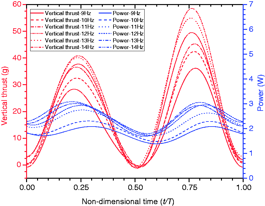
Figures 9 to 13 show the vertical thrust history synchronized with power consumption for one flapping cycle. The positive values dominate the force profiles in both half flapping strokes: downstroke and upstroke, resulting in positive cycle-averaged vertical thrust. The results indicate that the flapping frequency significantly influences the vertical force and power consumption. Higher flapping frequency yields a considerable increase in vertical thrust history at the region around the two peaks while the two troughs are almost not affected, and remain at nearly zero. Power consumption is shifted up in a similar pattern as the flapping frequency increases.
Time-dependent vertical thrust of Wing no. 1 for various frequencies from 9 Hz to 16 Hz.
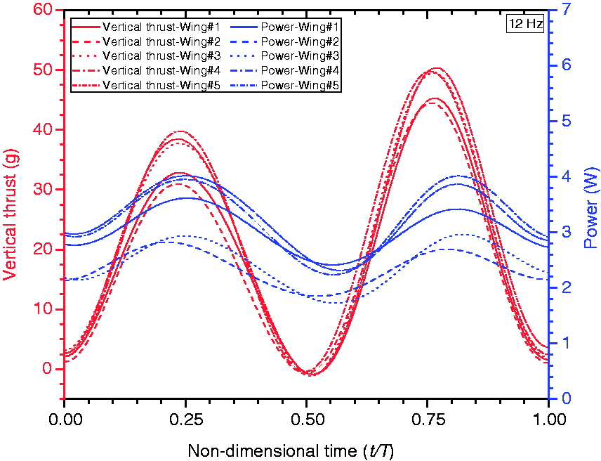
Figure 14 shows comparisons of vertical thrusts and power consumption of five wing configurations at a flapping frequency of 12 Hz for one flapping cycle. It can be seen that the wings with more rigid leading edge (Group 2, 0.7 mm carbon tube leading edge) significantly increase the two vertical thrust peaks when compared with the wings with less rigid leading edge (Group 1, 0.6 mm carbon rod leading edge); this result is similar to the work done by Ho et al.
16
The two troughs in the vertical thrust are not affected by the wing spanwise flexibility in both Groups 1 and 2, and remain the same value at nearly zero. In general, the wings with the same wing leading edge stiffness (0.7 mm carbon tube, 0.6 mm carbon rod) produce similar vertical thrust history; only slightly difference was observed, see Figure 14. It is suggested that the wing leading edge stiffness plays a major role in vertical thrust production than the wing chordwise flexibility.
Time-dependent vertical thrust of Wing no. 2 for various frequencies from 9 Hz to 15.9 Hz. Time-dependent vertical thrust of Wing no. 3 for various frequencies from 9 Hz to 14 Hz. Time-dependent vertical thrust of Wing no. 4 for various frequencies from 9 Hz to 13 Hz. Time-dependent vertical thrust of Wing no. 5 for various frequencies from 9 Hz to 14 Hz. Comparison of vertical thrusts and power consumption for five wing configurations at a selected flapping frequency of 12 Hz for one flapping cycle.


Maximum flapping frequency and vertical thrust
Given the same motor and gearbox, the maximum flapping frequency of the FW-MAV is depended on not only wing mass or inertia but also wing frontal area which is determined by the wing area projected on the plane perpendicular to the wing motion direction. Larger frontal wing area is subjected to more drag, and vice versa. When the wing configurations (wing leading edge and wing supporting veins) are changed, the wing deformation as well as wing rotation angle is passively changed during flapping motion. The wing deformation in spanwise and chordwise as well as wing rotation changes the frontal area of the flapping wing, resulting in change of drag acting on the wing. Therefore, different wing configuration has different flapping frequency at a given throttle level.
Figure 15 shows the maximum flapping frequency and vertical thrust of five wing configurations at maximum throttle level. The results indicate that the wings in each group (Groups 1 and 2) show similar maximum frequency and vertical thrust. Moreover, it was observed from the high speed images of wing motion that the wings in Group 1 (Wing no. 1 and Wing no. 2) had larger wing deformation in spanwise direction than the wings in Group 2 (Wing no. 3, Wing no. 4, and Wing no. 5). Phase delay of wing tip displacement, i.e. the wing tip and wing root move in opposite direction, was observed only in the wings in Group 1, based on the results shown in Figure 15, it can be concluded that maximum flapping frequency and vertical thrust mostly depend on wing leading edge stiffness in spanwise direction, slightly change in chordwise stiffness plays marginal role in contribution to the maximum frequency and vertical thrust.
Maximum flapping frequency and vertical thrust of various wing configurations at full throttle level from the radio transmitter.
Cycle-averaged vertical thrust and power consumption
The results shown in Figure 16 indicate almost a nearly linear relationship between cycle-averaged vertical thrust and flapping frequency for all wing configurations. Theoretically, the vertical thrust or lift is proportional to the velocity or frequency square. Therefore, the nearly linear relationship obtained from the experiment can be explained by the induced velocity which reduces the effective angle of attack on the flapping wing. The induced velocity tends to increase as the flapping frequency increases, thus, resulting in reducing effective angle of attack on the flapping wing or resulting in reducing vertical thrust on the wing. Again, it can be seen that the wings with the same leading edge stiffness produce similar cycle-averaged vertical thrust at the same flapping frequency. And the wings with more rigid leading edge generate more vertical thrust than the wings with less rigid leading edge.
Cycle-averaged vertical thrust w.r.t flapping frequency for five cases of wing configurations.
The power consumption also increases almost linearly with the flapping frequency. The wings with the same leading edge stiffness show the similar trend in power consumption, see Figure 17.
Cycle-averaged electrical power consumption w.r.t flapping frequency for five cases of wing configurations.
Figure 18 indicates the thrust-to-power ratio for each wing configuration. This curve is relatively flat with respect to frequency; there is about one unit difference from 9 Hz to the maximum flapping frequency of each wing. Wing no. 3 shows similar cycle-averaged vertical thrust to the Wing no. 4 and Wing no. 5 while consuming less power, resulting in the highest thrust-to-power ratio among the five wings. This is due to the more uniform wing rotation from wing root to wing tip, and positive wing camber created during flapping compared with the other wings, which was observed by the high speed images of wing motion. Wing no. 1 produces comparable vertical thrust, but consumes more power at frequencies lower than 14 Hz, resulting in inefficiency of thrust-to-power ratio. Overall, it is clear that spanwise wing flexibility influences both the vertical thrust history and power consumption, while the chordwise wing flexibility plays a marginal effect. The wings with the same leading edge stiffness produce similar patterns of both vertical thrust and power consumption histories, and also similar trend in cycle-averaged vertical thrust and power consumption.
Cycle-averagde thrust-to-power ratio w.r.t flapping frequency for five cases of wing configurations.
Conclusion
Experiments have been conducted to investigate the wing flexibility on vertical thrust production and power consumption of a FW-MAV with double wing clap-and-fling effects, namely FlowerFly, which has two pairs of wings and a weight of 14.5 g. In summary, the following conclusions can be derived from this study:
Two vertical thrust peaks with different magnitude and two vertical thrust troughs with almost zero magnitude were observed within one flapping cycle. Due to the passive wing rotation mechanism used in the FW-MAV, the vertical thrust peaks at about 25% and 75% flapping cycle, respectively, are created by the wing fling rather than the wing clap. The lower and higher peaks occur at the end of wing fling during downstroke and upstroke, respectively. Wings with the same leading edge stiffness produce similar vertical thrust history and cycle-averaged vertical thrust. At the same flapping frequency, wings with stiffer leading edge produce higher thrust peaks, resulting in larger cycle-averaged thrust compared with the wings with less leading stiffness. Wing chordwise stiffness plays a marginal role in both vertical thrust history and cycle-averaged thrust. At a flapping frequency of 9 Hz, the FlowerFly is about to produce enough vertical thrust for lift-off. Higher flapping frequency produces larger vertical thrust peaks while thrust troughs remain unchanged at almost zero value.
Footnotes
Declaration of conflicting interests
The author(s) declared no potential conflicts of interest with respect to the research, authorship, and/or publication of this article.
Funding
The author(s) received no financial support for the research, authorship, and/or publication of this article.